2014 NISSAN TEANA fuse
[x] Cancel search: fusePage 3947 of 4801

SEC-122
< DTC/CIRCUIT DIAGNOSIS >
POWER SUPPLY AND GROUND CIRCUIT
POWER SUPPLY AND GROUND CIRCUIT
Diagnosis ProcedureINFOID:0000000009956232
Regarding Wiring Diagram information, refer to BCS-55, "Wiring Diagram".
1. CHECK FUSE AND FUSIBLE LINK
Check that the following fuse and fusible link are not blown.
Is the fuse or fusible link blown?
YES >> Replace the blown fuse or fusible link after repairing the affected circuit.
NO >> GO TO 2
2. CHECK POWER SUPPLY CIRCUIT
1. Disconnect BCM connector M21.
2. Check voltage between BCM connector M21 terminals 131, 139 and ground.
Is the inspection result normal?
YES >> GO TO 3
NO >> Repair or replace harness or connectors.
3. CHECK GROUND CIRCUIT
Check continuity between BCM connector M21 terminals 134, 143 and ground.
Is the inspection result normal?
YES >> Inspection End.
NO >> Repair or replace harness or connectors.
Terminal No. Signal name Fuse and fusible link No.
139 Fusible link battery power I (40A)
131 BCM battery fuse 1 (10A)
BCM GroundVo l ta g e
(Approx.)
Connector Terminal
M21 131
— Battery voltage
139
BCM Ground Continuity
Connector Terminal
M21 134
—Yes
143
Revision: November 20132014 Altima NAMRevision: November 20132014 Altima NAM
Page 3952 of 4801
SECURITY INDICATOR LAMPSEC-127
< DTC/CIRCUIT DIAGNOSIS >
C
D E
F
G H
I
J
L
M A
B
SEC
N
O P
SECURITY INDICATOR LAMP
Component Function CheckINFOID:0000000009461192
1.CHECK FUNCTION
1. Perform THEFT IND in ACTIVE TEST mode of IMMU of BCM using CONSULT.
2. Check security indicator lamp operation.
Is the inspection result normal?
YES >> Inspection End.
NO >> Go to SEC-127, "Diagnosis Procedure"
.
Diagnosis ProcedureINFOID:0000000009461193
Regarding Wiring Diagram information, refer to SEC-50, "Wiring Diagram".
1.CHECK SECURITY INDICATOR LAMP POWER SUPPLY CIRCUIT
1. Turn ignition switch OFF.
2. Disconnect combination meter connector.
3. Check voltage between combination meter harness connector and ground.
Is the inspection result normal?
YES >> GO TO 2.
NO-1 >> Check 10 A fuse [No. 13, lo cated in the fuse block (J/B)].
NO-2 >> Check harness for open or short between combination meter and fuse.
2.CHECK SECURITY INDICATOR LAMP SIGNAL
1. Connect combination meter connector.
2. Disconnect BCM connector.
3. Check voltage between BCM harness connector and ground.
Is the inspection result normal?
YES >> GO TO 3.
NO >> GO TO 4.
3.REPLACE BCM
1. Replace BCM. Refer to BCS-80, "Removal and Installation"
.
2. Perform initialization of BCM and registration of all Intelligent Keys using CONSULT.
>> Inspection End.
Test item Description
THEFT IND ON
Security indicator lamp Illuminates
OFF Does not illuminate
(+) (–) Voltage (V)
Combination meter
Connector Terminal M24 22 Ground Battery voltage
(+) (–) Voltage (V)
BCM
Connector Terminal M17 18 Ground Battery voltage
Revision: November 20132014 Altima NAMRevision: November 20132014 Altima NAM
Page 4008 of 4801
DIAGNOSIS SYSTEM (AIR BAG)SRC-15
< SYSTEM DESCRIPTION >
C
D E
F
G
I
J
K L
M A
B
SRC
N
O P
DIAGNOSIS SYSTEM (AIR BAG)
Diagnosis DescriptionINFOID:0000000009460723
CAUTION:
• Do not use electrical test equipment on any circui t related to the SRS unless instructed to do so in
this Service Manual. SRS wiring harnesses can be id entified by yellow and/or orange harness con-
nectors.
• Do not attempt to repair, splice or modify SRS wiring harnesses. If a harness is damaged, replace it
with a new one.
• Keep ground connections clean.
HOW TO PERFORM TROUBLE DIAGNOSES FOR QUICK AND ACCURATE REPAIR
1. Obtain information about the symptom.
- WHAT - vehicle model
- WHEN - date, frequencies
- WHERE - road conditions
- HOW - operating conditions, symptoms, passengers
2. Perform Preliminary Check.
-Battery
- Fuses
- Harness connections
DIAGNOSIS METHODS
SRS self-diagnosis results can be read by using the AIR BAG warning lamp or CONSULT.
The User Mode is for the customer (driver). This m ode warns the driver of a system malfunction through the
AIR BAG warning lamp.
The Diagnosis Mode is for the technician. This mode hel ps the technician locate the malfunctioning circuit or
part.
SRS Operation CheckINFOID:0000000009460724
USER MODE
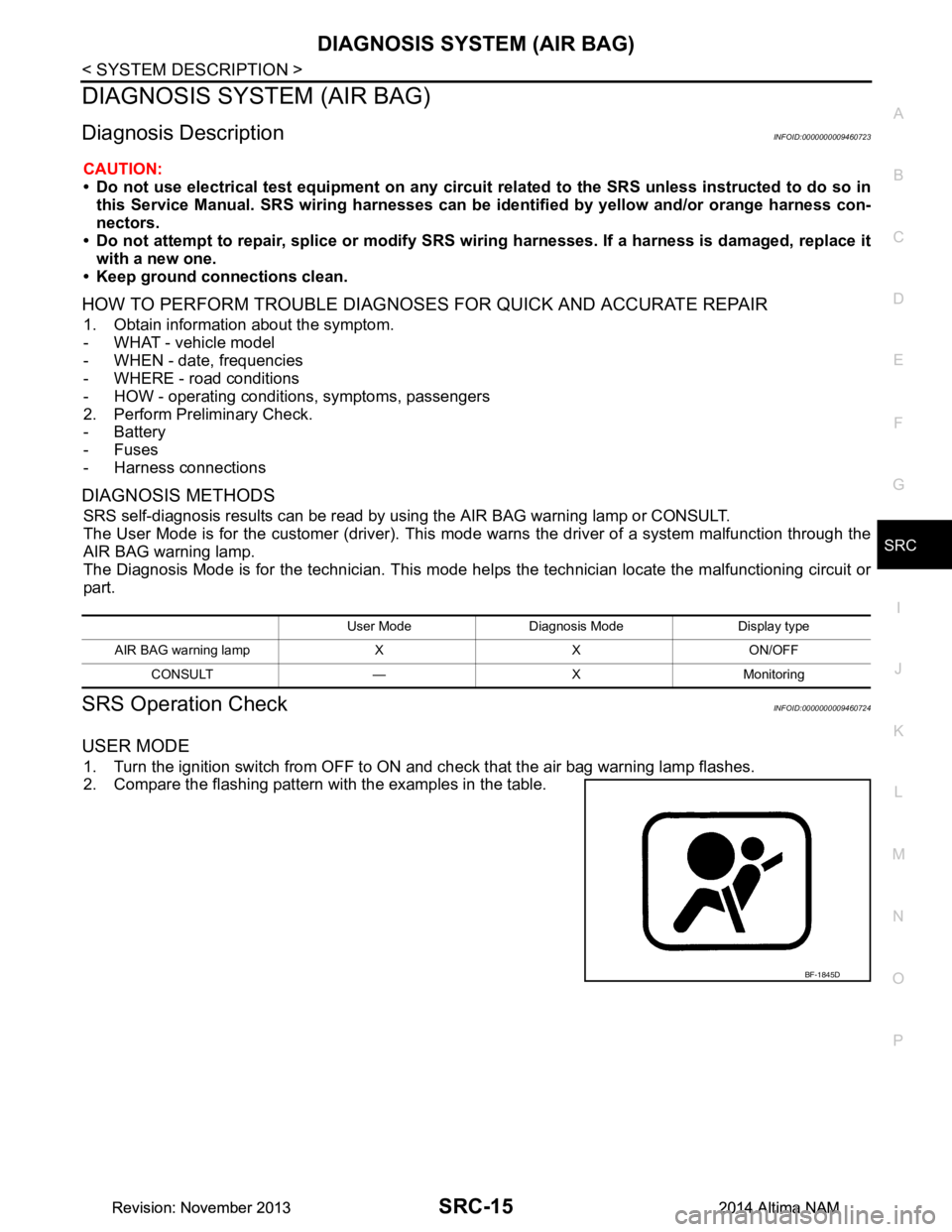
1. Turn the ignition switch from OFF to ON and check that the air bag warning lamp flashes.
2. Compare the flashing pattern with the examples in the table.
User Mode Diagnosis Mode Display type
AIR BAG warning lamp X X ON/OFF CONSULT — X Monitoring
BF-1845D
Revision: November 20132014 Altima NAMRevision: November 20132014 Altima NAM
Page 4090 of 4801

B1428 SEAT BELT BUCKLE SWITCH LHSRC-97
< DTC/CIRCUIT DIAGNOSIS >
C
D E
F
G
I
J
K L
M A
B
SRC
N
O P
YES >> Refer to SRC-97, "Diagnosis Procedure".
NO >> Inspection End.
Diagnosis ProcedureINFOID:0000000009460794
1.SEAT BELT WARNING LIGHT
Turn ignition switch ON.
Does the seat belt warning lamp stay on after lamp check?
YES >> GO TO 2
NO >> • Check 10A fuse [No. 13, loca ted in the fuse block (J/B)].
• Check seat belt buckle switch LH.
• Check harness between combination meter and seat belt buckle switch LH.
• Check harness between seat belt buckle switch LH and ground.
• Check harness between combination meter and air bag diagnosis sensor unit.
• Check combination meter. Refer to MWI-27, "Fail-Safe"
.
2.SEAT BELT BUCKLE LH
Fasten the seat belt buckle LH.
Does the seat belt warning lamp go OFF?
YES >> Check harness between combination meter and air bag diagnosis sensor unit.
NO >> • Check seat belt buckle switch LH. • Check harness between combination meter and seat belt buckle switch LH.
• Check harness between combination meter and air bag diagnosis sensor unit.
Revision: November 20132014 Altima NAMRevision: November 20132014 Altima NAM
Page 4101 of 4801
SRC-108
< SYMPTOM DIAGNOSIS >
SRS AIR BAG WARNING LAMP DOES NOT TURN ON
SYMPTOM DIAGNOSIS
SRS AIR BAG WARNING LAMP DOES NOT TURN ON
AIR BAG Warning Lamp Does Not Turn OnINFOID:0000000009460813
1.CHECK METER FUSE
Check the 10A fuse [No. 13, loca ted in the fuse block (J/B)].
Is the fuse blown?
YES >> GO TO 2
NO >> GO TO 3
2.REPLACE METER FUSE AND CHECK AGAIN
Replace 10A fuse [No. 13, located in the fu se block (J/B)] and turn ignition switch ON.
Does the fuse blow again?
YES >> Replace fuse and harness.
NO >> Inspection End.
3.CHECK HARNESS CONNECTIONS BET WEEN AIR BAG DIAGNOSIS SENSOR UNIT AND COMBINA-
TION METER
Inspect the harness and connectors between the air bag diagnosis sensor unit and the combination meter.
Do the harness or connectors have any visible damage?
YES >> Replace harness.
NO >> GO TO 4
4.CHECK COMBINATION METER
Disconnect the air bag diagnosis sensor unit harness connectors and turn ignition switch ON.
Does AIR BAG warning lamp turn on?
YES >> Replace the air bag diagnosis sensor unit. Refer to SR-26, "Removal and Installation".
NO >> Replace the combination meter. Refer to MWI-82, "Removal and Installation"
.
Revision: November 20132014 Altima NAMRevision: November 20132014 Altima NAM
Page 4102 of 4801
SRS AIR BAG WARNING LAMP DOES NOT TURN OFF
SRC-109
< SYMPTOM DIAGNOSIS >
C
D E
F
G
I
J
K L
M A
B
SRC
N
O P
SRS AIR BAG WARNING LAMP DOES NOT TURN OFF
AIR BAG Warning Lamp Does Not Turn OffINFOID:0000000009460814
1.CHECK CONDITION OF AIR BAG MODULE
Inspect for any deployed air bag modules or seat belt pre-tensioners.
Are any air bag modules or seat belt pre-tensioners deployed?
YES >> Refer to SR-5, "For Frontal Collision" or SR-7, "For Side and Rollover Collision".
NO >> GO TO 2
2.CHECK THE AIR BAG FUSE
Check 10A fuse [No. 32, locat ed in the fuse block (J/B)].
Is the fuse blown?
YES >> GO TO 3
NO >> GO TO 4
3.CHECK AIR BAG FUSE AGAIN
Replace 10A fuse [No. 32, located in the fu se block (J/B)] and turn ignition switch ON.
Does the fuse blow again?
YES >> Replace fuse and harness.
NO >> Inspection End.
4.CHECK AIR BAG DIAGNOSIS SENSOR UNIT
Connect CONSULT.
Is
“AIR BAG” displayed on CONSULT?
YES >> GO TO 5
NO >> Visually inspect the air bag diagnosis sensor unit harness connections. If the connections are OK,
replace the air bag diagnosis sensor unit. Refer to SR-26, "Removal and Installation"
.
5.CHECK HARNESS CONNECTION
Check for loose connections between the combination meter and the air bag diagnosis sensor unit.
Are there any loose connections?
YES >> Properly connect the combination meter and air bag diagnosis sensor unit harness connectors. If AIR BAG warning lamp still does not tu rn off, replace the wiring harness.
NO >> Replace air bag diagnosis sensor unit. Refer to SR-26, "Removal and Installation"
.
Revision: November 20132014 Altima NAMRevision: November 20132014 Altima NAM
Page 4103 of 4801

SRC-110
< SYMPTOM DIAGNOSIS >
SEAT BELT WARNING SYSTEM
SEAT BELT WARNING SYSTEM
Seat Belt Warning System Does Not FunctionINFOID:0000000009460815
(For US/CAN models only)
1.SEAT BELT WARNING LIGHT
Turn ignition switch ON.
Does the seat belt warning lamp come ON?
YES >> GO TO 2
NO >> • Check 10A fuse [No. 13, located in the fuse block (J/B)].
• Check seat belt buckle switch (driver seat).
• Check harness between combination meter and seat belt buckle switch (driver seat).
• Check combination meter. Refer to MWI-27, "Fail-Safe"
.
2.SEAT BELT BUCKLE (DRIVER SEAT)
Fasten the seat belt buckle (driver seat).
Does the seat belt warning lamp go OFF?
YES >> GO TO 3
NO >> • Check seat belt buckle switch (driver seat). • Check harness between combination meter and seat belt buckle switch (driver seat).
3.OCCUPANT CLASSIFICATION SYSTEM
Have a helper sit in the passenger seat.
Does the seat belt warning lamp go ON?
YES >> GO TO 4
NO >> • Check occupant classification system. Refer to SRC-12, "OCCUPANT CLASSIFICATION SYS-
TEM : System Description".
• Check harness between occupant classification control unit and air bag diagnosis sensor unit.
4.SEAT BELT BUCKLE (PASSENGER SEAT)
Fasten the seat belt buckle (passenger seat).
Does the seat belt warning lamp go OFF?
YES >> System OK.
NO >> • Check seat belt buckle switch (passenger seat). • Check harness between seat belt buckle switch (passenger seat) and air bag diagnosis sensorunit.
• Replace air bag diagnosis sensor unit. Refer to SR-26, "Removal and Installation"
.
Revision: November 20132014 Altima NAMRevision: November 20132014 Altima NAM
Page 4124 of 4801
POWER SUPPLY AND GROUND CIRCUITST-21
< DTC/CIRCUIT DIAGNOSIS >
C
D E
F
H I
J
K L
M A
B
ST
N
O P
DTC/CIRCUIT DIAGNOSIS
POWER SUPPLY AND GROUND CIRCUIT
A/C AUTO AMP.
A/C AUTO AMP. : Diagnosis ProcedureINFOID:0000000009952472
Regarding Wiring Diagram information, refer to HAC-34, "Wiring Diagram".
1.CHECK FUSE
Check fuses [No. 14, 25 and 30, loca ted in the fuse block (J/B)].
NOTE:
Refer to PG-70, "Terminal Arrangement"
.
Is the inspection result normal?
YES >> GO TO 2.
NO >> Replace the blown fuse after repairing the affected circuit.
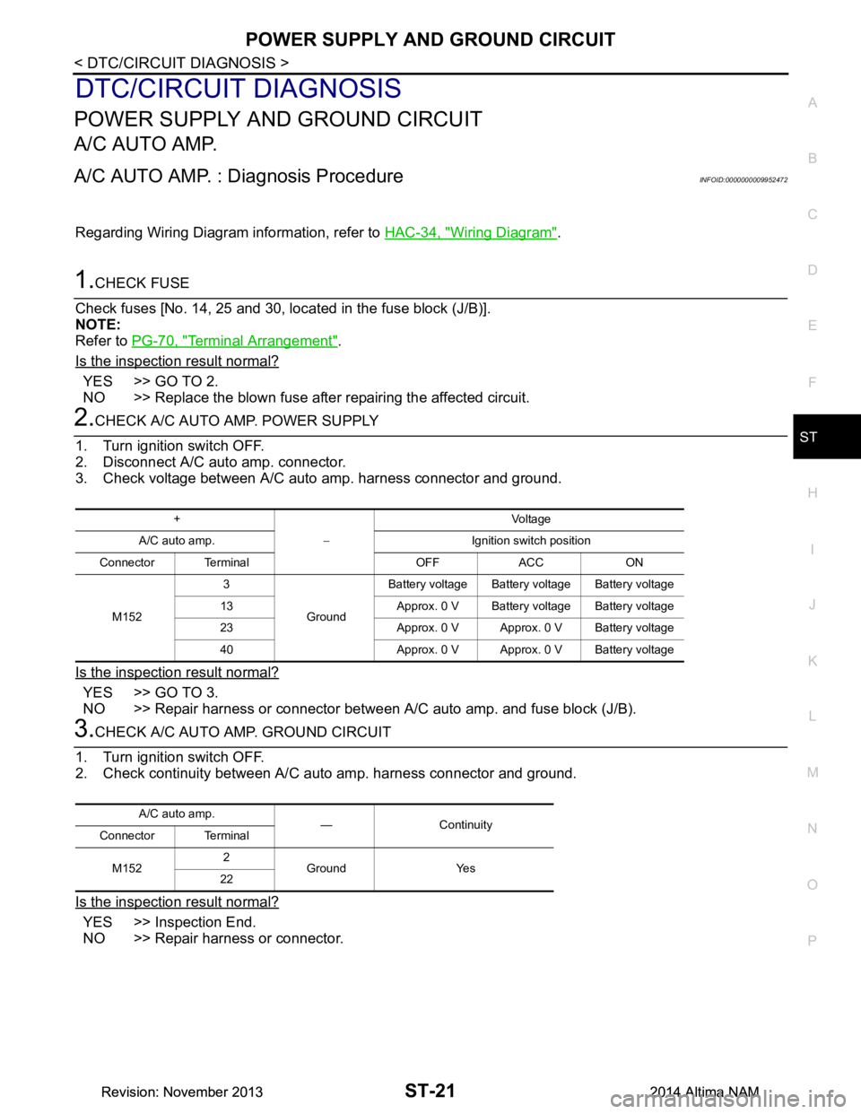
2.CHECK A/C AUTO AMP. POWER SUPPLY
1. Turn ignition switch OFF.
2. Disconnect A/C auto amp. connector.
3. Check voltage between A/C auto amp. harness connector and ground.
Is the inspection result normal?
YES >> GO TO 3.
NO >> Repair harness or connector between A/C auto amp. and fuse block (J/B).
3.CHECK A/C AUTO AMP. GROUND CIRCUIT
1. Turn ignition switch OFF.
2. Check continuity between A/C aut o amp. harness connector and ground.
Is the inspection result normal?
YES >> Inspection End.
NO >> Repair harness or connector.
+
− Voltag e
A/C auto amp. Ignition switch position
Connector Terminal OFF ACC ON
M152 3
GroundBattery voltage Battery voltage Battery voltage
13 Approx. 0 V Battery voltage Battery voltage
23 Approx. 0 V Approx. 0 V Battery voltage
40 Approx. 0 V Approx. 0 V Battery voltage
A/C auto amp. — Continuity
Connector Terminal
M152 2
Ground Yes
22
Revision: November 20132014 Altima NAMRevision: November 20132014 Altima NAM