2014 NISSAN TEANA brake fluid
[x] Cancel search: brake fluidPage 3218 of 4801
MA-34
< PERIODIC MAINTENANCE >
CHASSIS AND BODY MAINTENANCE
34. Select “Data Monitor” in “TRANSMISSION” using CONSULT.
35. Select “CONFORM CVTF DETERIORTN”.
36. Select “Erase”.
37. Stop the engine.
CVT FLUID : AdjustmentINFOID:0000000009464569
CAUTION:
• During adjustment of the CVT fluid level, check CO NSULT so that the oil temperature may be main-
tained from 35 to 45 °C (95 to 113 °F).
• During adjustment of the CVT fluid level, check that the engine speed is maintaining 500 rpm.
• Use caution when looking into the drain hole as th ere is a risk of dripping fluid entering the eye.
1. Check that the selector lever is in the “P ” position, then completely engage the parking brake.
2. Start the engine.
3. Adjust the CVT fluid temperature to be approximately 40 °C (104 °F).
NOTE:
The CVT fluid is largely affected by temperature. Therefore be sure to use CONSULT and check the
“FLUID TEMP” under “TRANSMISSION” in “Data Monitor” while adjusting.
4. While depressing the brake pedal, shift the selector lever to the entire position from “P” to “DS”, and shift it to the “P” position.
NOTE:
Hold the lever at each position for 5 seconds.
5. Lift up the vehicle.
6. Check that there is no CVT fluid leakage.
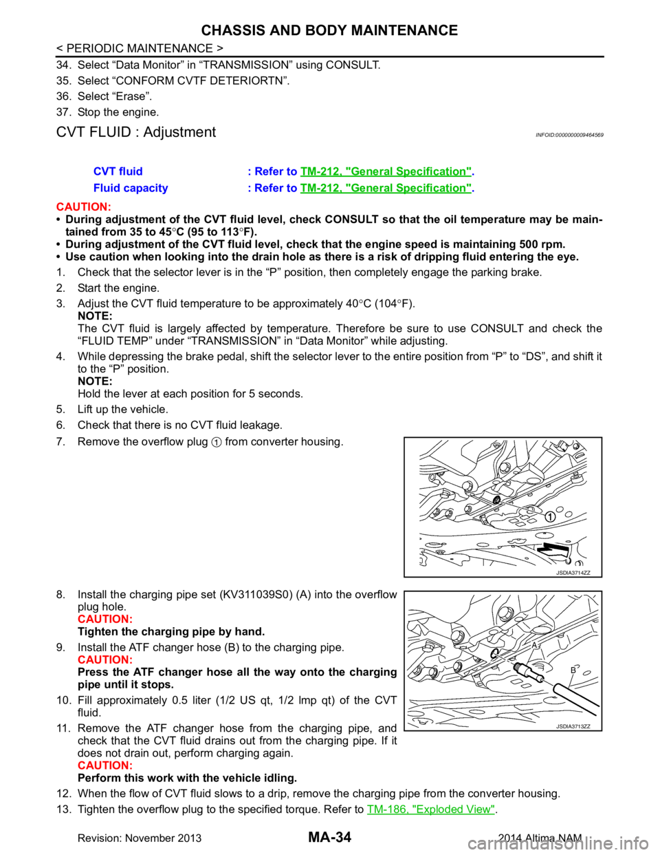
7. Remove the overflow plug from converter housing.
8. Install the charging pipe set (KV311039S0) (A) into the overflow plug hole.
CAUTION:
Tighten the charging pipe by hand.
9. Install the ATF changer hose (B) to the charging pipe. CAUTION:
Press the ATF changer hose all the way onto the charging
pipe until it stops.
10. Fill approximately 0.5 liter (1/2 US qt, 1/2 lmp qt) of the CVT
fluid.
11. Remove the ATF changer hose from the charging pipe, and check that the CVT fluid drains out from the charging pipe. If it
does not drain out, perform charging again.
CAUTION:
Perform this work with the vehicle idling.
12. When the flow of CVT fluid slows to a drip, re move the charging pipe from the converter housing.
13. Tighten the overflow plug to the specified torque. Refer to TM-186, "Exploded View"
.
CVT fluid : Refer to
TM-212, "General Specification"
.
Fluid capacity : Refer to TM-212, "General Specification"
.
JSDIA3714ZZ
JSDIA3713ZZ
Revision: November 20132014 Altima NAM
Page 3219 of 4801
CHASSIS AND BODY MAINTENANCEMA-35
< PERIODIC MAINTENANCE >
C
D E
F
G H
I
J
K L
M B
MA
N
O A
CAUTION:
Do not reuse O-ring.
14. Lift down the vehicle.
15. Stop the engine.
CVT FLUID : RE0F10EINFOID:0000000009464570
CVT FLUID : InspectionINFOID:0000000009464571
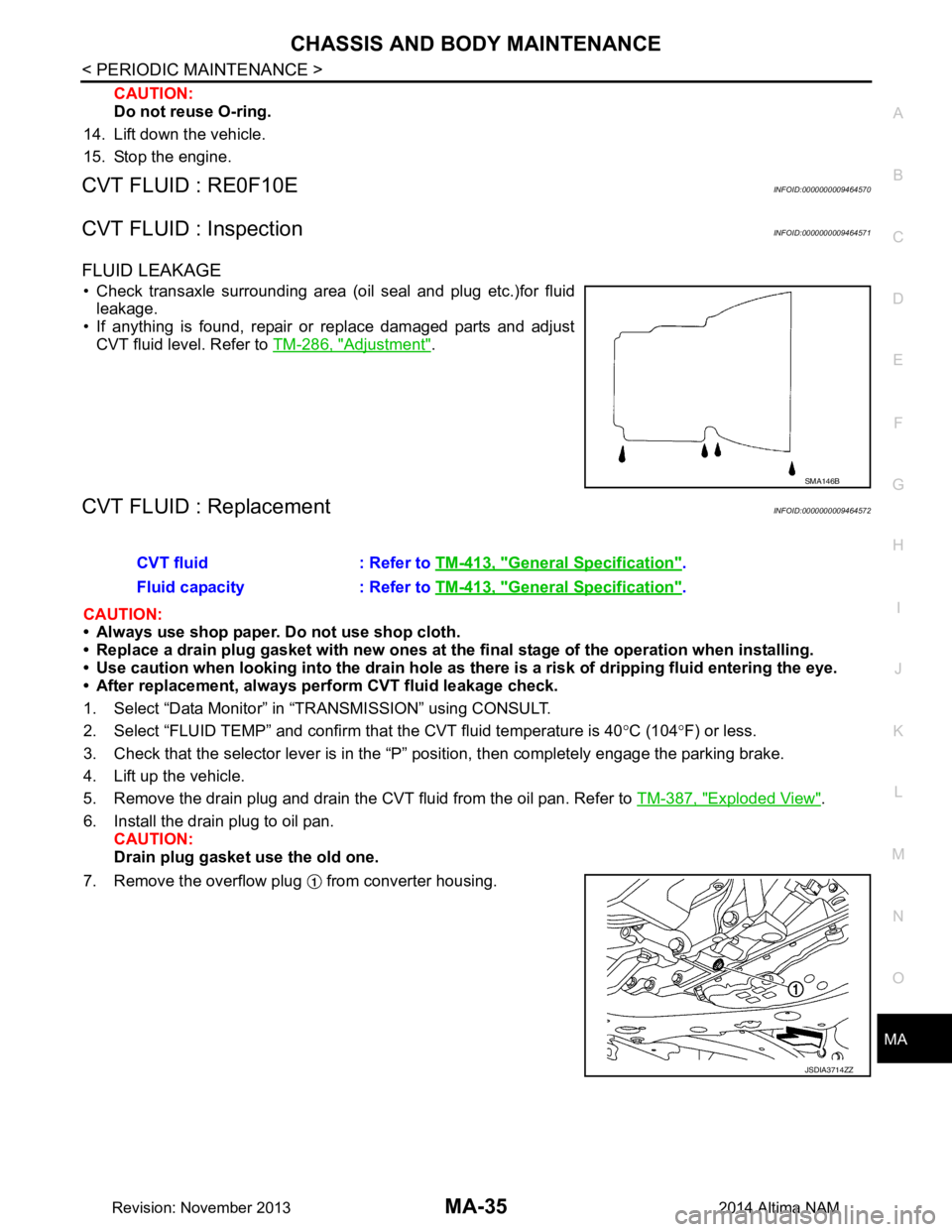
FLUID LEAKAGE
• Check transaxle surrounding area (oil seal and plug etc.)for fluid leakage.
• If anything is found, repair or replace damaged parts and adjust
CVT fluid level. Refer to TM-286, "Adjustment"
.
CVT FLUID : ReplacementINFOID:0000000009464572
CAUTION:
• Always use shop paper. Do not use shop cloth.
• Replace a drain plug gasket with new ones at the fi nal stage of the operation when installing.
• Use caution when looking into the drain hole as there is a risk of dripping fluid entering the eye.
• After replacement, always pe rform CVT fluid leakage check.
1. Select “Data Monitor” in “TRANSMISSION” using CONSULT.
2. Select “FLUID TEMP” and confirm t hat the CVT fluid temperature is 40°C (104 °F) or less.
3. Check that the selector lever is in the “P ” position, then completely engage the parking brake.
4. Lift up the vehicle.
5. Remove the drain plug and drain the CVT fluid from the oil pan. Refer to TM-387, "Exploded View"
.
6. Install the drain plug to oil pan. CAUTION:
Drain plug gasket use the old one.
7. Remove the overflow plug from converter housing.
SMA146B
CVT fluid : Refer to TM-413, "General Specification".
Fluid capacity : Refer to TM-413, "General Specification"
.
JSDIA3714ZZ
Revision: November 20132014 Altima NAM
Page 3220 of 4801
MA-36
< PERIODIC MAINTENANCE >
CHASSIS AND BODY MAINTENANCE
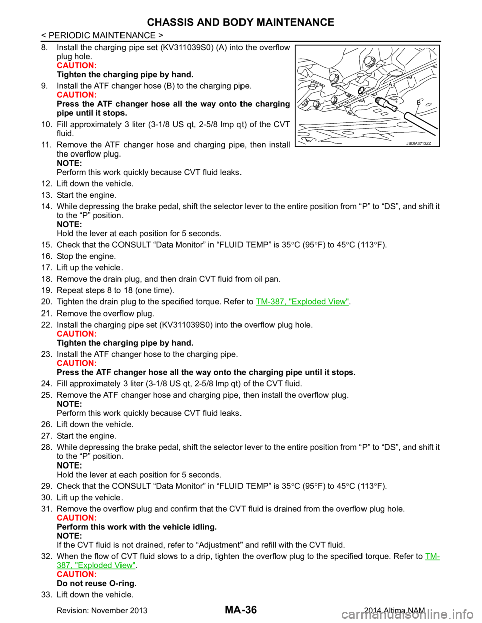
8. Install the charging pipe set (KV311039S0) (A) into the overflowplug hole.
CAUTION:
Tighten the charging pipe by hand.
9. Install the ATF changer hose (B) to the charging pipe. CAUTION:
Press the ATF changer hose all the way onto the charging
pipe until it stops.
10. Fill approximately 3 liter (3-1/8 US qt, 2-5/8 lmp qt) of the CVT
fluid.
11. Remove the ATF changer hose and charging pipe, then install the overflow plug.
NOTE:
Perform this work quickly because CVT fluid leaks.
12. Lift down the vehicle.
13. Start the engine.
14. While depressing the brake pedal, shift the selector lever to the entire position from “P” to “DS”, and shift it to the “P” position.
NOTE:
Hold the lever at each position for 5 seconds.
15. Check that the CONSULT “Data Monitor” in “FLUID TEMP” is 35 °C (95 °F) to 45 °C (113 °F).
16. Stop the engine.
17. Lift up the vehicle.
18. Remove the drain plug, and then drain CVT fluid from oil pan.
19. Repeat steps 8 to 18 (one time).
20. Tighten the drain plug to the specified torque. Refer to TM-387, "Exploded View"
.
21. Remove the overflow plug.
22. Install the charging pipe set (KV311039S0) into the overflow plug hole. CAUTION:
Tighten the charging pipe by hand.
23. Install the ATF changer hose to the charging pipe. CAUTION:
Press the ATF changer hose all the way onto the charging pipe until it stops.
24. Fill approximately 3 liter (3-1/8 US qt, 2-5/8 lmp qt) of the CVT fluid.
25. Remove the ATF changer hose and charging pipe, then install the overflow plug. NOTE:
Perform this work quickly because CVT fluid leaks.
26. Lift down the vehicle.
27. Start the engine.
28. While depressing the brake pedal, shift the selector lever to the entire position from “P” to “DS”, and shift it to the “P” position.
NOTE:
Hold the lever at each position for 5 seconds.
29. Check that the CONSULT “Data Monitor” in “FLUID TEMP” is 35 °C (95 °F) to 45 °C (113 °F).
30. Lift up the vehicle.
31. Remove the overflow plug and confirm that the CV T fluid is drained from the overflow plug hole.
CAUTION:
Perform this work with the vehicle idling.
NOTE:
If the CVT fluid is not drained, refer to “Adjustment” and refill with the CVT fluid.
32. When the flow of CVT fluid slows to a drip, tighten the overflow plug to the specified torque. Refer to TM-
387, "Exploded View".
CAUTION:
Do not reuse O-ring.
33. Lift down the vehicle.
JSDIA3713ZZ
Revision: November 20132014 Altima NAM
Page 3221 of 4801
CHASSIS AND BODY MAINTENANCEMA-37
< PERIODIC MAINTENANCE >
C
D E
F
G H
I
J
K L
M B
MA
N
O A
34. Select “Data Monitor” in “TRANSMISSION” using CONSULT.
35. Select “CONFORM CVTF DETERIORTN”.
36. Select “Erase”.
37. Stop the engine.
CVT FLUID : AdjustmentINFOID:0000000009464573
CAUTION:
• During adjustment of the CVT fluid level, check CO NSULT so that the oil temperature may be main-
tained from 35 to 45 °C (95 to 113 °F).
• During adjustment of the CVT fluid level, check that the engine speed is maintaining 500 rpm.
• Use caution when looking into the drain hole as there is a risk of dripping fluid entering the eye.
1. Check that the selector lever is in the “P ” position, then completely engage the parking brake.
2. Start the engine.
3. Adjust the CVT fluid temperature to be approximately 40 °C (104 °F).
NOTE:
The CVT fluid is largely affected by temperature. Therefore be sure to use CONSULT and check the
“FLUID TEMP” under “TRA NSMISSION” in “Data Monitor” while adjusting.
4. While depressing the brake pedal, shift the selector leve r to the entire position from “P” to “DS”, and shift it
to the “P” position.
NOTE:
Hold the lever at each position for 5 seconds.
5. Lift up the vehicle.
6. Check that there is no CVT fluid leakage.
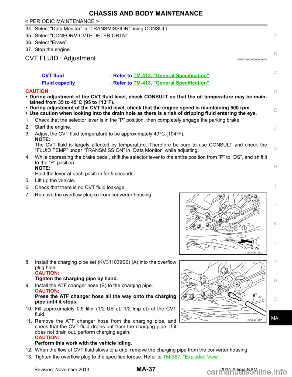
7. Remove the overflow plug from converter housing.
8. Install the charging pipe set (KV311039S0) (A) into the overflow plug hole.
CAUTION:
Tighten the charging pipe by hand.
9. Install the ATF changer hose (B) to the charging pipe. CAUTION:
Press the ATF changer hose all the way onto the charging
pipe until it stops.
10. Fill approximately 0.5 liter (1/2 US qt, 1/2 lmp qt) of the CVT
fluid.
11. Remove the ATF changer hose from the charging pipe, and check that the CVT fluid drains out from the charging pipe. If it
does not drain out, perform charging again.
CAUTION:
Perform this work with the vehicle idling.
12. When the flow of CVT fluid slows to a drip, re move the charging pipe from the converter housing.
13. Tighten the overflow plug to the specified torque. Refer to TM-387, "Exploded View"
.
CVT fluid : Refer to
TM-413, "General Specification"
.
Fluid capacity : Refer to TM-413, "General Specification"
.
JSDIA3714ZZ
JSDIA3713ZZ
Revision: November 20132014 Altima NAM
Page 3224 of 4801
MA-40
< PERIODIC MAINTENANCE >
CHASSIS AND BODY MAINTENANCE
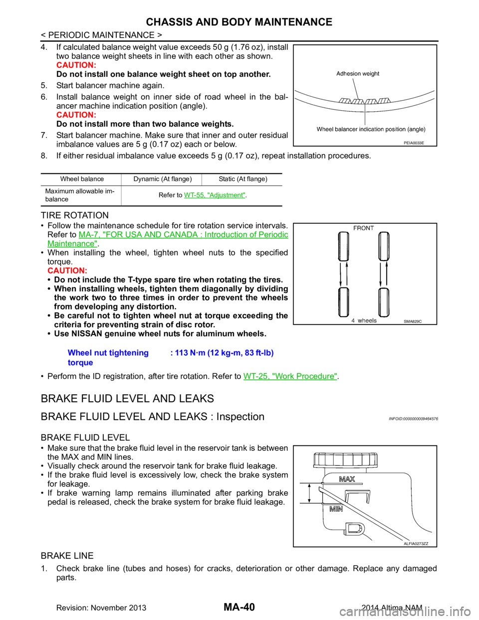
4. If calculated balance weight value exceeds 50 g (1.76 oz), installtwo balance weight sheets in line with each other as shown.
CAUTION:
Do not install one balance weight sheet on top another.
5. Start balancer machine again.
6. Install balance weight on inner side of road wheel in the bal- ancer machine indication position (angle).
CAUTION:
Do not install more than two balance weights.
7. Start balancer machine. Make sure that inner and outer residual imbalance values are 5 g (0.17 oz) each or below.
8. If either residual imbalance value exceeds 5 g (0.17 oz), repeat installation procedures.
TIRE ROTATION
• Follow the maintenance schedule for tire rotation service intervals.
Refer to MA-7, "FOR USA AND CANADA : Introduction of Periodic
Maintenance".
• When installing the wheel, tighten wheel nuts to the specified torque.
CAUTION:
• Do not include the T-type spare tire when rotating the tires.
• When installing wheels, tighten them diagonally by dividing
the work two to three times in order to prevent the wheels
from developing any distortion.
• Be careful not to tighten wheel nut at torque exceeding the criteria for preventing strain of disc rotor.
• Use NISSAN genuine wheel nuts for aluminum wheels.
• Perform the ID registration, after tire rotation. Refer to WT-25, "Work Procedure"
.
BRAKE FLUID LEVEL AND LEAKS
BRAKE FLUID LEVEL AND LEAKS : InspectionINFOID:0000000009464576
BRAKE FLUID LEVEL
• Make sure that the brake fluid level in the reservoir tank is between
the MAX and MIN lines.
• Visually check around the reservoir tank for brake fluid leakage.
• If the brake fluid level is excessively low, check the brake system for leakage.
• If brake warning lamp remains illuminated after parking brake
pedal is released, check the brake system for brake fluid leakage.
BRAKE LINE
1. Check brake line (tubes and hoses) for cracks, deterioration or other damage. Replace any damaged
parts.
Wheel balance Dynamic (At flange) Static (At flange)
Maximum allowable im-
balance Refer to
WT-55, "Adjustment"
.
PEIA0033E
Wheel nut tightening
torque : 113 N·m (12 kg-m, 83 ft-lb)
SMA829C
ALFIA0273ZZ
Revision: November 20132014 Altima NAM
Page 3225 of 4801
CHASSIS AND BODY MAINTENANCEMA-41
< PERIODIC MAINTENANCE >
C
D E
F
G H
I
J
K L
M B
MA
N
O A
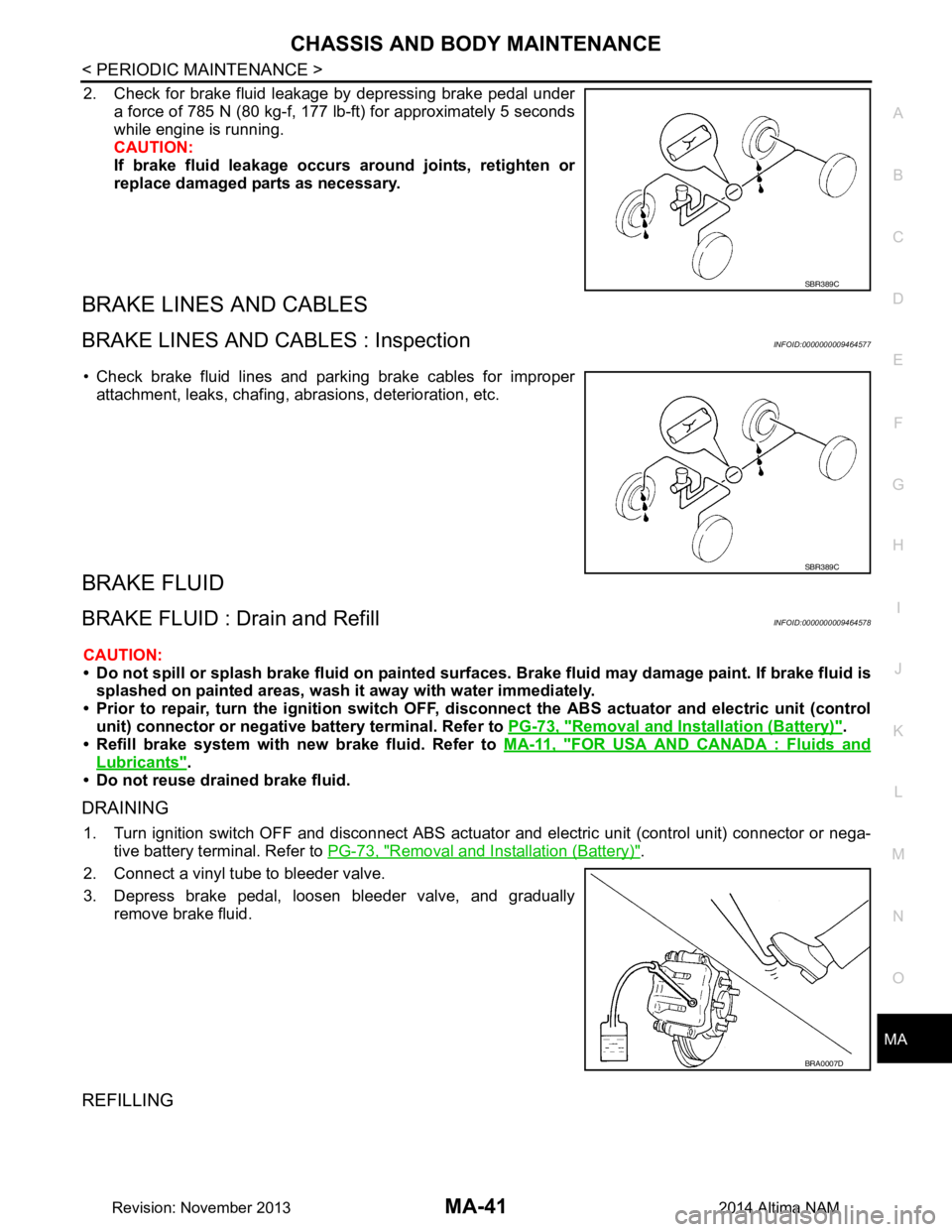
2. Check for brake fluid leakage by depressing brake pedal under
a force of 785 N (80 kg-f, 177 lb-ft) for approximately 5 seconds
while engine is running.
CAUTION:
If brake fluid leakage occurs around joints, retighten or
replace damaged parts as necessary.
BRAKE LINES AND CABLES
BRAKE LINES AND CABLES : InspectionINFOID:0000000009464577
• Check brake fluid lines and parking brake cables for improper attachment, leaks, chafing, abrasions, deterioration, etc.
BRAKE FLUID
BRAKE FLUID : Drain and RefillINFOID:0000000009464578
CAUTION:
• Do not spill or splash brake fluid on painted surf aces. Brake fluid may damage paint. If brake fluid is
splashed on painted areas, wash it away with water immediately.
• Prior to repair, turn the ignition switch OFF, disconnect the ABS actuator and electric unit (control
unit) connector or negative battery terminal. Refer to PG-73, "Removal and Installation (Battery)"
.
• Refill brake system with new brake fluid. Refer to MA-11, "FOR USA AND CANADA : Fluids and
Lubricants".
• Do not reuse drained brake fluid.
DRAINING
1. Turn ignition switch OFF and disconnect ABS actuat or and electric unit (control unit) connector or nega-
tive battery terminal. Refer to PG-73, "Removal and Installation (Battery)"
.
2. Connect a vinyl tube to bleeder valve.
3. Depress brake pedal, loosen bleeder valve, and gradually remove brake fluid.
REFILLING
SBR389C
SBR389C
BRA0007D
Revision: November 20132014 Altima NAM
Page 3226 of 4801
MA-42
< PERIODIC MAINTENANCE >
CHASSIS AND BODY MAINTENANCE
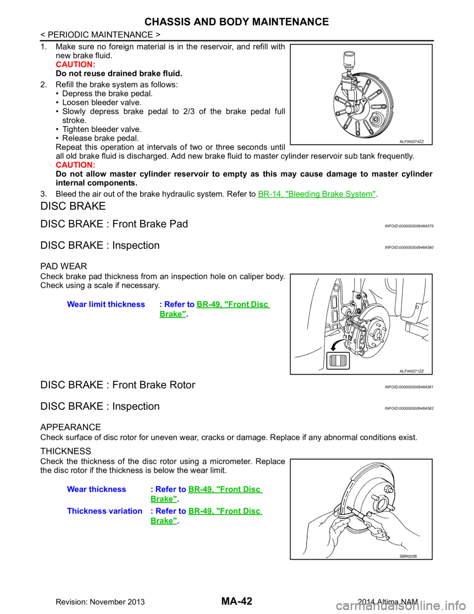
1. Make sure no foreign material is in the reservoir, and refill withnew brake fluid.
CAUTION:
Do not reuse drained brake fluid.
2. Refill the brake system as follows: • Depress the brake pedal.
• Loosen bleeder valve.
• Slowly depress brake pedal to 2/3 of the brake pedal full stroke.
• Tighten bleeder valve.
• Release brake pedal.
Repeat this operation at intervals of two or three seconds until
all old brake fluid is discharged. Add new brake flui d to master cylinder reservoir sub tank frequently.
CAUTION:
Do not allow master cylinder reservoir to empt y as this may cause damage to master cylinder
internal components.
3. Bleed the air out of the brake hydraulic system. Refer to BR-14, "Bleeding Brake System"
.
DISC BRAKE
DISC BRAKE : Front Brake PadINFOID:0000000009464579
DISC BRAKE : InspectionINFOID:0000000009464580
PA D W E A R
Check brake pad thickness from an inspection hole on caliper body.
Check using a scale if necessary.
DISC BRAKE : Front Brake RotorINFOID:0000000009464581
DISC BRAKE : InspectionINFOID:0000000009464582
APPEARANCE
Check surface of disc rotor for uneven wear, cracks or damage. Replace if any abnormal conditions exist.
THICKNESS
Check the thickness of the disc rotor using a micrometer. Replace
the disc rotor if the thickness is below the wear limit.
ALFIA0274ZZ
Wear limit thickness : Refer to BR-49, "Front Disc
Brake".
ALFIA0271ZZ
Wear thickness : Refer to BR-49, "Front Disc
Brake".
Thickness variation : Refer to BR-49, "Front Disc
Brake".
SBR020B
Revision: November 20132014 Altima NAM
Page 3227 of 4801
CHASSIS AND BODY MAINTENANCEMA-43
< PERIODIC MAINTENANCE >
C
D E
F
G H
I
J
K L
M B
MA
N
O A
DISC BRAKE : Rear Brake PadINFOID:0000000009464583
DISC BRAKE : InspectionINFOID:0000000009464584
PA D W E A R
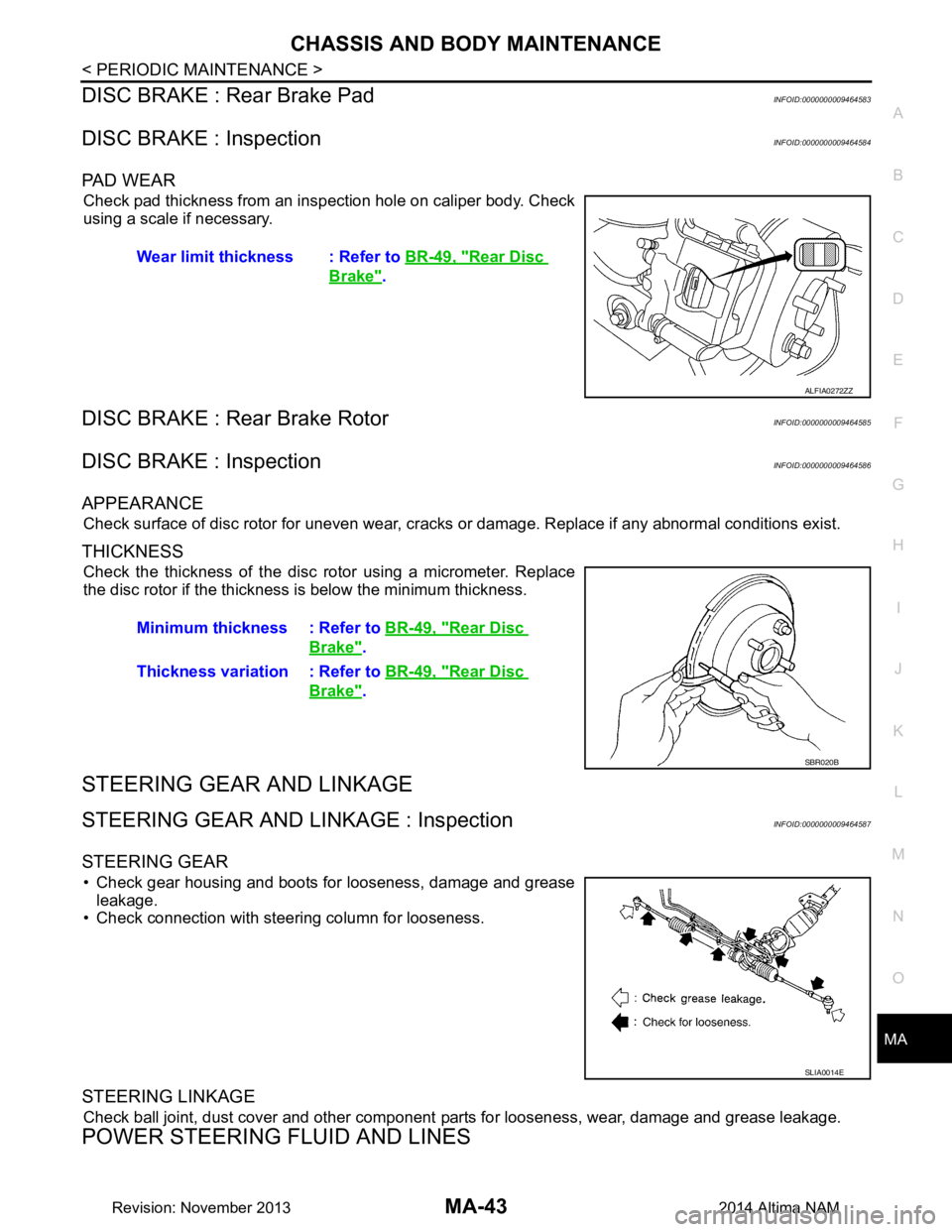
Check pad thickness from an inspection hole on caliper body. Check
using a scale if necessary.
DISC BRAKE : Rear Brake RotorINFOID:0000000009464585
DISC BRAKE : InspectionINFOID:0000000009464586
APPEARANCE
Check surface of disc rotor for uneven wear, cracks or damage. Replace if any abnormal conditions exist.
THICKNESS
Check the thickness of the disc rotor using a micrometer. Replace
the disc rotor if the thickness is below the minimum thickness.
STEERING GEAR AND LINKAGE
STEERING GEAR AND LINKAGE : InspectionINFOID:0000000009464587
STEERING GEAR
• Check gear housing and boots for looseness, damage and grease leakage.
• Check connection with steering column for looseness.
STEERING LINKAGE
Check ball joint, dust cover and other component parts for looseness, wear, damage and grease leakage.
POWER STEERING FLUID AND LINES
Wear limit thickness : Refer to BR-49, "Rear Disc
Brake".
ALFIA0272ZZ
Minimum thickness : Refer to BR-49, "Rear Disc
Brake".
Thickness variation : Refer to BR-49, "Rear Disc
Brake".
SBR020B
SLIA0014E
Revision: November 20132014 Altima NAM