2014 NISSAN QUEST engine
[x] Cancel search: enginePage 168 of 482
SPA2858
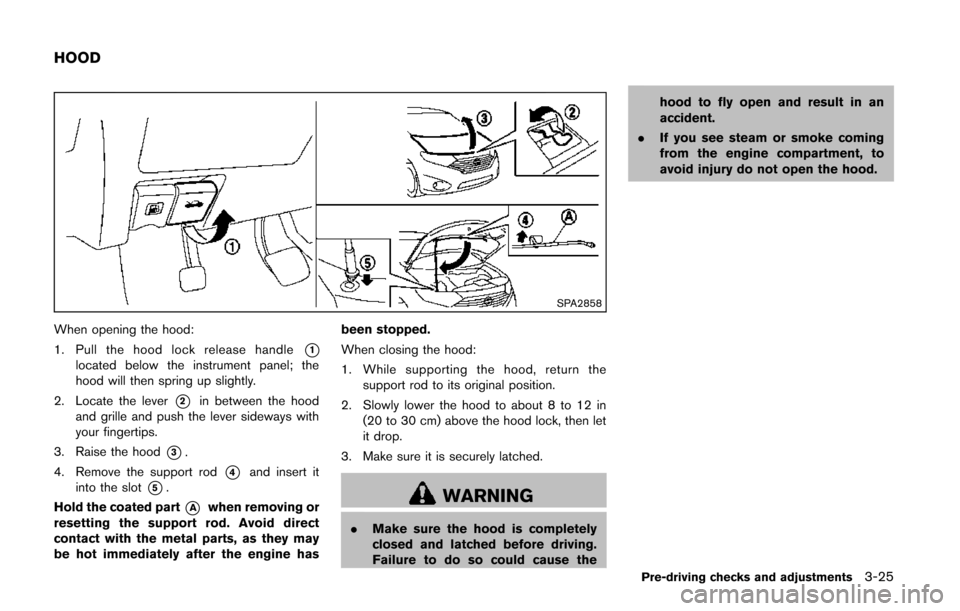
When opening the hood:
1. Pull the hood lock release handle
*1located below the instrument panel; the
hood will then spring up slightly.
2. Locate the lever
*2in between the hood
and grille and push the lever sideways with
your fingertips.
3. Raise the hood
*3.
4. Remove the support rod
*4and insert it
into the slot
*5.
Hold the coated part
*Awhen removing or
resetting the support rod. Avoid direct
contact with the metal parts, as they may
be hot immediately after the engine has been stopped.
When closing the hood:
1. While supporting the hood, return the
support rod to its original position.
2. Slowly lower the hood to about 8 to 12 in (20 to 30 cm) above the hood lock, then let
it drop.
3. Make sure it is securely latched.WARNING
. Make sure the hood is completely
closed and latched before driving.
Failure to do so could cause the hood to fly open and result in an
accident.
. If you see steam or smoke coming
from the engine compartment, to
avoid injury do not open the hood.
Pre-driving checks and adjustments3-25
HOOD
Page 173 of 482
3-30Pre-driving checks and adjustments
SPA2824
LIFT GATE RELEASE
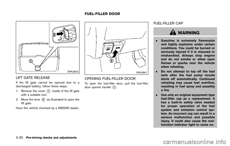
If the lift gate cannot be opened due to a
discharged battery, follow these steps.
1. Remove the cover
*1inside of the lift gate
with a suitable tool.
2. Move the lever
*2as illustrated to open the
lift gate.
Have the vehicle checked by a NISSAN dealer.
SPA2861
OPENING FUEL-FILLER DOOR
To open the fuel-filler door, pull the fuel-filler
door opener handle
*1.
FUEL-FILLER CAP
WARNING
. Gasoline is extremely flammable
and highly explosive under certain
conditions. You could be burned or
seriously injured if it is misused or
mishandled. Always stop engine
and do not smoke or allow open
flames or sparks near the vehicle
when refueling.
. Do not attempt to top off the fuel
tank after the fuel pump nozzle
shuts off automatically. Continued
refueling may cause fuel overflow,
resulting in fuel spray and possibly
a fire.
. Use only an original equipment type
fuel-filler cap as a replacement. It
has a built-in safety valve needed
for proper operation of the fuel
system and emission control sys-
tem. An incorrect cap can result in a
serious malfunction and possible
injury. It could also cause the mal-
function indicator light to come on.
FUEL-FILLER DOOR
Page 181 of 482
3-38Pre-driving checks and adjustments
The indicator light for the pushed memory
switch will stay on for approximately 5
seconds after pushing the switch.
If memory is stored in the same memory
switch, the previous memory will be deleted.
Linking Intelligent Key to a stored mem-
ory position
The Intelligent Key can be linked to a stored
memory position with the following procedure.
1. Follow one of the steps for storing a memoryposition.
. While the indicator light for the memory
switch being set is illuminated for 5 sec-
onds, push the
button on the Intelligent
Key.
. Push the ignition switch to the OFF position,
and then push the SET switch. Push the
button while pushing the memory button
while the indicator light stays on for approxi-
mately 5 seconds.
If the indicator light blinks, the Intelligent Key is
linked to that memory setting.
Push the ignition switch to the OFF position, and
then push the
button on the Intelligent Key.
The driver’s seat and outside mirrors will move to
the memorized position.
Confirming memory storage
. Push the ignition switch to the ON position
and push the SET switch. If the main
memory has not been stored, the indicator
light will come on for approximately 0.5
second. When the memory has stored in
position, the indicator light will stay on for
approximately 5 seconds.
. If the battery cable is disconnected, or if the
fuse opens, the memory will be canceled. In
this case, reset the desired position using
the previous procedure.
. If optional keys are added to your vehicle,
the memory storage procedure to switch 1
or 2 and linking Intelligent Key procedure to
a stored memory position should be per-
formed again for each Intelligent Key. For
additional Intelligent Key information, see
“Keys” (P.3-3) .
Selecting the memorized position
1. Move the shift lever to the P (Park) position.
2. Use one of the following methods to move
the driver’s seat and outside mirrors.
.Push the ignition switch to the ONposition and push the memory switch (1
or 2) .
.Within 45 seconds of opening thedriver’s door, push the memory switch (1 or 2) .
The driver’s seat and outside mirrors will
move to the memorized position with the
indicator light flashing, and then the light will
stay on for approximately 5 seconds.
SYSTEM OPERATION
The automatic drive positioner system will not
work or will stop operating under the following
conditions:
. When the vehicle speed is above 4 MPH (7
km/h) (entry/exit function) .
. When the vehicle is driven (memory sto-
rage).
. When the adjusting switch for the driver’s
seat is turned on while the automatic drive
positioner is operating.
. When the driver’s seat and outside mirrors
have already been moved to the memorized
position.
. When no position is stored in the memory
switch.
. When the engine is started while moving the
automatic drive positioner.
. When the shift lever is moved from the P
(Park) position to any other position. (How-
ever, it will not be canceled while the driver’s
seat is returning to the previous positions
(entry/exit function).)
Page 187 of 482
4-4Monitor, heater, air conditioner, audio, phone and voice recognition systems
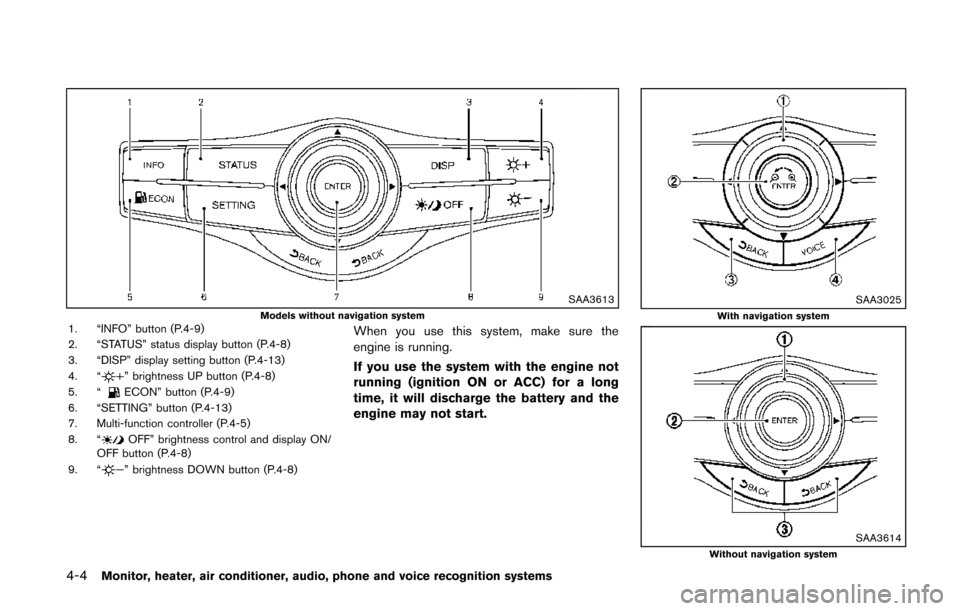
SAA3613Models without navigation system1. “INFO” button (P.4-9)
2. “STATUS” status display button (P.4-8)
3. “DISP” display setting button (P.4-13)
4. “
” brightness UP button (P.4-8)
5. “ECON” button (P.4-9)
6. “SETTING” button (P.4-13)
7. Multi-function controller (P.4-5)
8. “
OFF” brightness control and display ON/
OFF button (P.4-8)
9. “
” brightness DOWN button (P.4-8)
When you use this system, make sure the
engine is running.
If you use the system with the engine not
running (ignition ON or ACC) for a long
time, it will discharge the battery and the
engine may not start.
SAA3025With navigation system
SAA3614Without navigation system
Page 194 of 482
SAA2481Models with navigation system
JVH0183MModels without navigation system
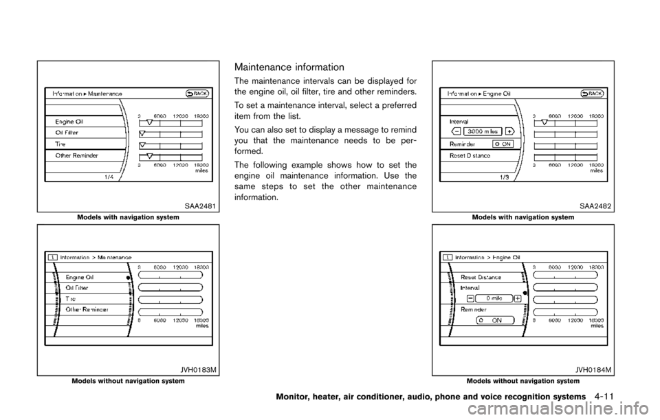
Maintenance information
The maintenance intervals can be displayed for
the engine oil, oil filter, tire and other reminders.
To set a maintenance interval, select a preferred
item from the list.
You can also set to display a message to remind
you that the maintenance needs to be per-
formed.
The following example shows how to set the
engine oil maintenance information. Use the
same steps to set the other maintenance
information.
SAA2482Models with navigation system
JVH0184MModels without navigation system
Monitor, heater, air conditioner, audio, phone and voice recognition systems4-11
Page 222 of 482
SAA3676Side
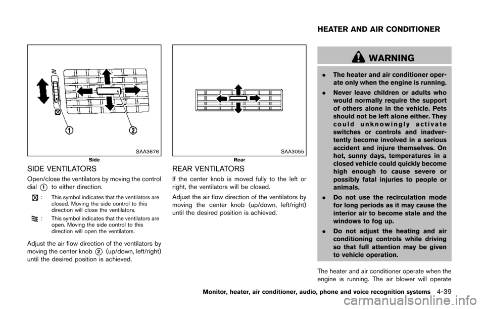
SIDE VENTILATORS
Open/close the ventilators by moving the control
dial
*1to either direction.
: This symbol indicates that the ventilators areclosed. Moving the side control to this
direction will close the ventilators.
: This symbol indicates that the ventilators areopen. Moving the side control to this
direction will open the ventilators.
Adjust the air flow direction of the ventilators by
moving the center knob
*2(up/down, left/right)
until the desired position is achieved.
SAA3055Rear
REAR VENTILATORS
If the center knob is moved fully to the left or
right, the ventilators will be closed.
Adjust the air flow direction of the ventilators by
moving the center knob (up/down, left/right)
until the desired position is achieved.
WARNING
. The heater and air conditioner oper-
ate only when the engine is running.
. Never leave children or adults who
would normally require the support
of others alone in the vehicle. Pets
should not be left alone either. They
could unknowingly activate
switches or controls and inadver-
tently become involved in a serious
accident and injure themselves. On
hot, sunny days, temperatures in a
closed vehicle could quickly become
high enough to cause severe or
possibly fatal injuries to people or
animals.
. Do not use the recirculation mode
for long periods as it may cause the
interior air to become stale and the
windows to fog up.
. Do not adjust the heating and air
conditioning controls while driving
so that full attention may be given
to vehicle operation.
The heater and air conditioner operate when the
engine is running. The air blower will operate
Monitor, heater, air conditioner, audio, phone and voice recognition systems4-39
HEATER AND AIR CONDITIONER
Page 223 of 482
4-40Monitor, heater, air conditioner, audio, phone and voice recognition systems
even if the engine is turned off and the ignition
switch is in the “ON” position.
NOTE:
.Odors from inside and outside the
vehicle can build up in the air condi-
tioner unit. Odor can enter the passen-
ger compartment through the vents.
. When parking, set the heater and air
conditioner controls to turn off air
recirculation to allow fresh air into the
passenger compartment. This should
help reduce odors inside the vehicle.
SAA3594
SAA3514
OPERATING TIPS (for automatic air
conditioner)
When the engine coolant temperature and
outside air temperature are low, the air flow
from the foot outlets may not operate. However,
this is not a malfunction. After the coolant
temperature warms up, the air flow from the
foot outlets will operate normally.
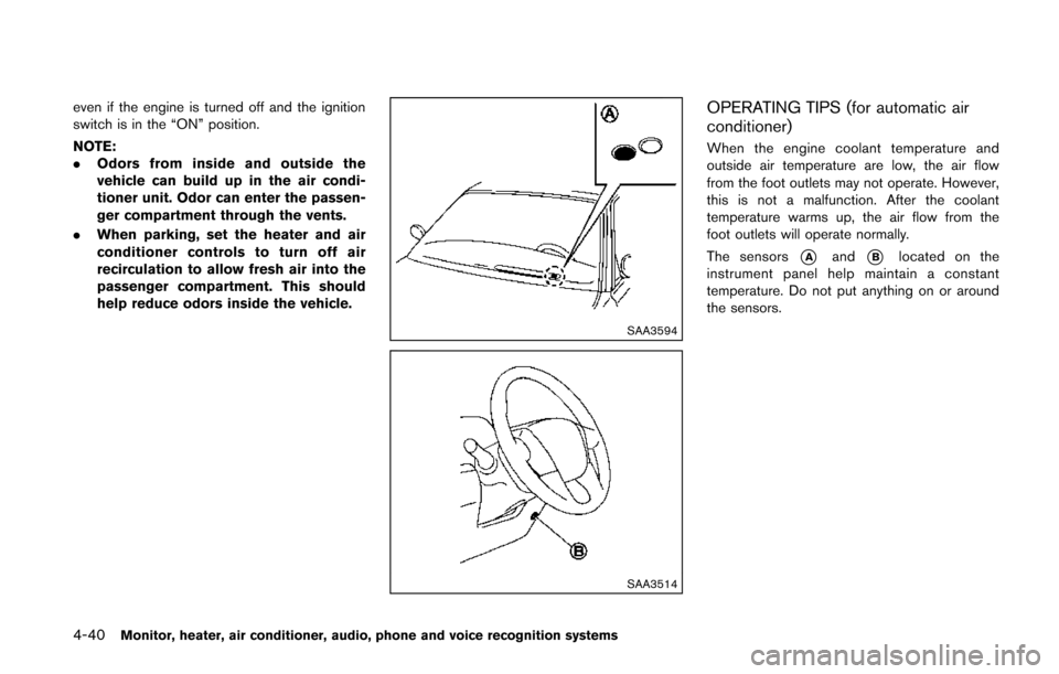
The sensors
*Aand*Blocated on the
instrument panel help maintain a constant
temperature. Do not put anything on or around
the sensors.
Page 236 of 482
IN-CABIN MICROFILTER
The climate control system is equipped with an
in-cabin microfilter which collects dirt, pollen,
dust, etc. To make sure the air conditioner heats,
defogs, and ventilates efficiently, replace the
filter in accordance with the maintenance
schedule in the NISSAN Service and Mainte-
nance Guide. To replace the filter, contact a
NISSAN dealer. A natural grape seed polyphe-
nol filter (if so equipped) collects and neutralizes
dirt, pollen, dust, etc.
The filter should be replaced if air flow is
extremely decreased or when windows fog
up easily when operating heater or air
conditioning system.
AUDIO OPERATION PRECAUTIONS
Radio
Push the ignition switch to the ACC or ON
position and push the radio band select button
to turn on the radio. If you listen to the radio with
the engine not running, the ignition switch
should be pushed to the ACC position.
Radio reception is affected by station signal
strength, distance from radio transmitter, build-
ings, bridges, mountains and other external
influences. Intermittent changes in reception
quality normally are caused by these external
influences.
Using a cellular phone in or near the
vehicle may influence radio reception
quality.
Radio reception:
Your NISSAN radio system is equipped with
state-of-the-art electronic circuits to enhance
radio reception. These circuits are designed to
extend reception range, and to enhance the
quality of that reception.
However there are some general characteristics
of both FM and AM radio signals that can affect
radio reception quality in a moving vehicle, even
when the finest equipment is used. These
characteristics are completely normal in a given
reception area, and do not indicate any mal-function in your NISSAN radio system.
Reception conditions will constantly change
because of vehicle movement. Buildings, terrain,
signal distance and interference from other
vehicles can work against ideal reception.
Described below are some of the factors that
can affect your radio reception.
Some cellular phones or other devices may
cause interference or a buzzing noise to come
from the audio system speakers. Storing the
device in a different location may reduce or
eliminate the noise.
Monitor, heater, air conditioner, audio, phone and voice recognition systems4-53
AUDIO SYSTEM