2014 NISSAN QUEST engine
[x] Cancel search: enginePage 101 of 482
2-22Instruments and controls
SIC4237
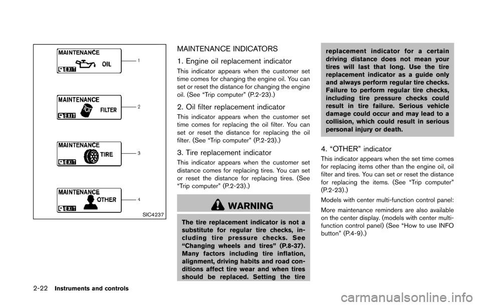
MAINTENANCE INDICATORS
1. Engine oil replacement indicator
This indicator appears when the customer set
time comes for changing the engine oil. You can
set or reset the distance for changing the engine
oil. (See “Trip computer” (P.2-23) .)
2. Oil filter replacement indicator
This indicator appears when the customer set
time comes for replacing the oil filter. You can
set or reset the distance for replacing the oil
filter. (See “Trip computer” (P.2-23).)
3. Tire replacement indicator
This indicator appears when the customer set
distance comes for replacing tires. You can set
or reset the distance for replacing tires. (See
“Trip computer” (P.2-23) .)
WARNING
The tire replacement indicator is not a
substitute for regular tire checks, in-
cluding tire pressure checks. See
“Changing wheels and tires” (P.8-37) .
Many factors including tire inflation,
alignment, driving habits and road con-
ditions affect tire wear and when tires
should be replaced. Setting the tirereplacement indicator for a certain
driving distance does not mean your
tires will last that long. Use the tire
replacement indicator as a guide only
and always perform regular tire checks.
Failure to perform regular tire checks,
including tire pressure checks could
result in tire failure. Serious vehicle
damage could occur and may lead to a
collision, which could result in serious
personal injury or death.
4. “OTHER” indicator
This indicator appears when the set time comes
for replacing items other than the engine oil, oil
filter and tires. You can set or reset the distance
for replacing the items. (See “Trip computer”
(P.2-23) .)
Models with center multi-function control panel:
More maintenance reminders are also available
on the center display. (models with center multi-
function control panel) (See “How to use INFO
button” (P.4-9).)
Page 104 of 482
SIC4702
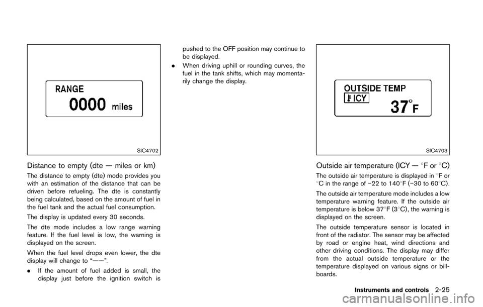
Distance to empty (dte — miles or km)
The distance to empty (dte) mode provides you
with an estimation of the distance that can be
driven before refueling. The dte is constantly
being calculated, based on the amount of fuel in
the fuel tank and the actual fuel consumption.
The display is updated every 30 seconds.
The dte mode includes a low range warning
feature. If the fuel level is low, the warning is
displayed on the screen.
When the fuel level drops even lower, the dte
display will change to “——”.
.If the amount of fuel added is small, the
display just before the ignition switch is pushed to the OFF position may continue to
be displayed.
. When driving uphill or rounding curves, the
fuel in the tank shifts, which may momenta-
rily change the display.
SIC4703
Outside air temperature (ICY — 8For8C)
The outside air temperature is displayed in 8For
8C in the range of −22 to 1408F(−30 to 608C) .
The outside air temperature mode includes a low
temperature warning feature. If the outside air
temperature is below 378F(3 8C) , the warning is
displayed on the screen.
The outside temperature sensor is located in
front of the radiator. The sensor may be affected
by road or engine heat, wind directions and
other driving conditions. The display may differ
from the actual outside temperature or the
temperature displayed on various signs or bill-
boards.
Instruments and controls2-25
Page 105 of 482
2-26Instruments and controls
SIC3678
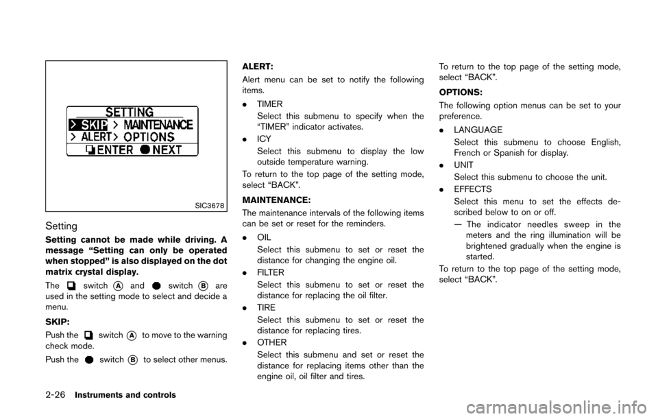
Setting
Setting cannot be made while driving. A
message “Setting can only be operated
when stopped” is also displayed on the dot
matrix crystal display.
The
switch*Aandswitch*Bare
used in the setting mode to select and decide a
menu.
SKIP:
Push the
switch*Ato move to the warning
check mode.
Push the
switch*Bto select other menus. ALERT:
Alert menu can be set to notify the following
items.
.
TIMER
Select this submenu to specify when the
“TIMER” indicator activates.
. ICY
Select this submenu to display the low
outside temperature warning.
To return to the top page of the setting mode,
select “BACK”.
MAINTENANCE:
The maintenance intervals of the following items
can be set or reset for the reminders.
. OIL
Select this submenu to set or reset the
distance for changing the engine oil.
. FILTER
Select this submenu to set or reset the
distance for replacing the oil filter.
. TIRE
Select this submenu to set or reset the
distance for replacing tires.
. OTHER
Select this submenu and set or reset the
distance for replacing items other than the
engine oil, oil filter and tires. To return to the top page of the setting mode,
select “BACK”.
OPTIONS:
The following option menus can be set to your
preference.
. LANGUAGE
Select this submenu to choose English,
French or Spanish for display.
. UNIT
Select this submenu to choose the unit.
. EFFECTS
Select this menu to set the effects de-
scribed below to on or off.
— The indicator needles sweep in the
meters and the ring illumination will be
brightened gradually when the engine is
started.
To return to the top page of the setting mode,
select “BACK”.
Page 108 of 482
by releasing the door inside lock knob, the
alarm will activate.)
How to stop an activated alarm
The alarm will stop by unlocking a door by
pushing the unlock button on the Intelligent Key,
the door handle request switch or using the
mechanical key. The alarm will not stop if the
ignition switch is pushed to the ACC or ON
position.
If the system does not operate as de-
scribed above, have it checked by a
NISSAN dealer.
NISSAN VEHICLE IMMOBILIZER SYS-
TEM
The NISSAN Vehicle Immobilizer System will not
allow the engine to start without the use of the
registered Intelligent Key.Never leave these
keys in the vehicle.
FCC Notice:
For USA:
This device complies with Part 15 of the
FCC Rules. Operation is subject to the
following two conditions:
(1) This device may not cause harmful
interference, and (2) this device must
accept any interference received, including
interference that may cause undesired operation.
Note: Changes or modifications not ex-
pressly approved by the party responsible
for compliance could void the user’s
authority to operate the equipment.
For Canada:
This device complies with RSS-210 of
Industry Canada. Operation is subject to
the following two conditions:
(1) this device may not cause interference,
and (2) this device must accept any inter-
ference, including interference that may
cause undesired operation of the device.
SIC2045
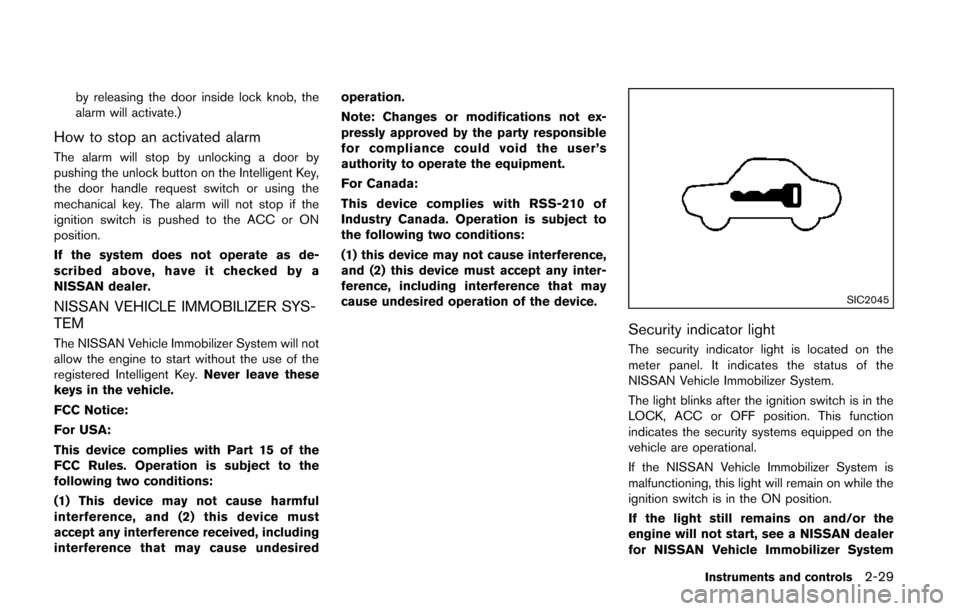
Security indicator light
The security indicator light is located on the
meter panel. It indicates the status of the
NISSAN Vehicle Immobilizer System.
The light blinks after the ignition switch is in the
LOCK, ACC or OFF position. This function
indicates the security systems equipped on the
vehicle are operational.
If the NISSAN Vehicle Immobilizer System is
malfunctioning, this light will remain on while the
ignition switch is in the ON position.
If the light still remains on and/or the
engine will not start, see a NISSAN dealer
for NISSAN Vehicle Immobilizer System
Instruments and controls2-29
Page 111 of 482
2-32Instruments and controls
window washer reservoir tank to
mix the washer fluid concentrate
and water.
If the rear window wiper operation is
interrupted by snow or ice, the wiper may
stop moving to protect its motor. If this
occurs, turn the wiper switch to the OFF
position and remove the snow or ice that is
on and around the wiper arms. In approxi-
mately 1 minute, turn the switch on again
to operate the wiper.
SIC3666
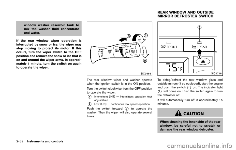
The rear window wiper and washer operate
when the ignition switch is in the ON position.
Turn the switch clockwise from the OFF position
to operate the wiper.
*1Intermittent (INT) — intermittent operation (not
adjustable)
*2Low (ON) — continuous low speed operation
Push the switch forward*3to operate the
washer. Then the wiper will also operate several
times.
SIC4718
To defog/defrost the rear window glass and
outside mirrors (if so equipped), start the engine
and push the switch
*1on. The indicator light
*2will come on. Push the switch again to turn
the defroster off.
It will automatically turn off in approximately 15
minutes.
CAUTION
When cleaning the inner side of the rear
window, be careful not to scratch or
damage the rear window defroster.
REAR WINDOW AND OUTSIDE
MIRROR DEFROSTER SWITCH
Page 114 of 482
seconds.
For automatic headlights off delay setting, see
“Vehicle information and settings (models with
center multi-function control panel)” (P.4-8).
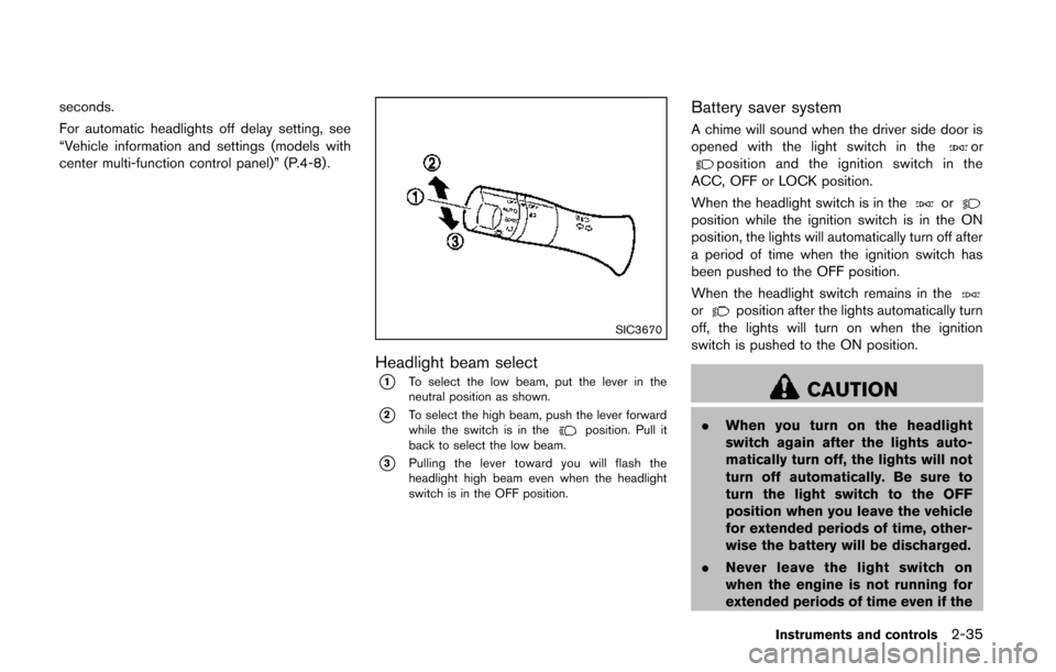
SIC3670
Headlight beam select
*1To select the low beam, put the lever in the
neutral position as shown.
*2To select the high beam, push the lever forward
while the switch is in theposition. Pull it
back to select the low beam.
*3Pulling the lever toward you will flash the
headlight high beam even when the headlight
switch is in the OFF position.
Battery saver system
A chime will sound when the driver side door is
opened with the light switch in theorposition and the ignition switch in the
ACC, OFF or LOCK position.
When the headlight switch is in the
orposition while the ignition switch is in the ON
position, the lights will automatically turn off after
a period of time when the ignition switch has
been pushed to the OFF position.
When the headlight switch remains in the
orposition after the lights automatically turn
off, the lights will turn on when the ignition
switch is pushed to the ON position.
CAUTION
. When you turn on the headlight
switch again after the lights auto-
matically turn off, the lights will not
turn off automatically. Be sure to
turn the light switch to the OFF
position when you leave the vehicle
for extended periods of time, other-
wise the battery will be discharged.
. Never leave the light switch on
when the engine is not running for
extended periods of time even if the
Instruments and controls2-35
Page 115 of 482
2-36Instruments and controls
headlights turn off automatically.
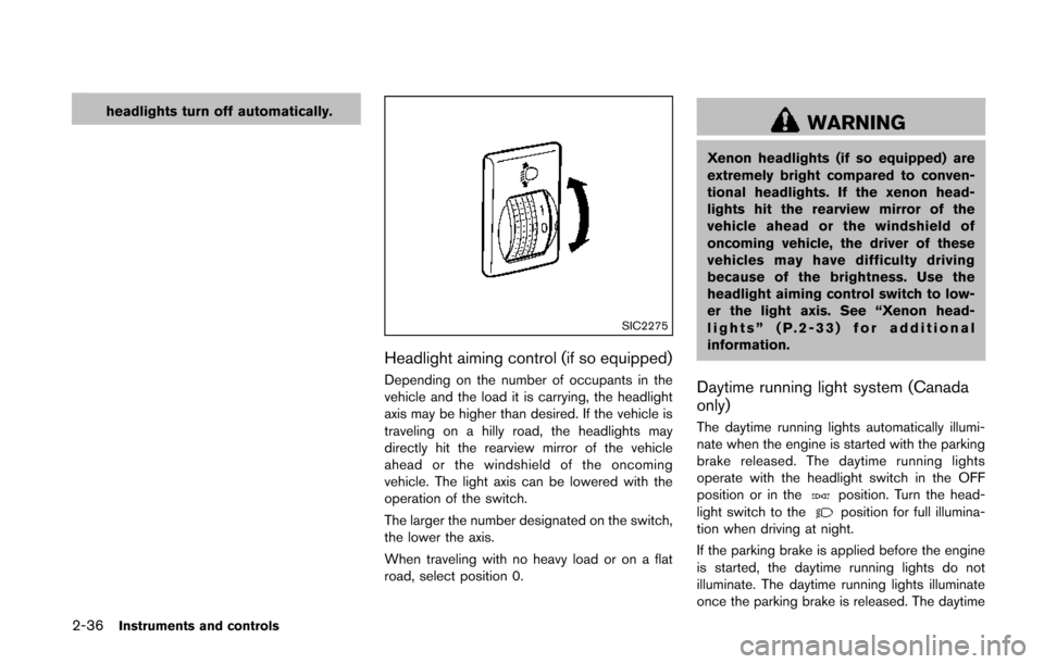
SIC2275
Headlight aiming control (if so equipped)
Depending on the number of occupants in the
vehicle and the load it is carrying, the headlight
axis may be higher than desired. If the vehicle is
traveling on a hilly road, the headlights may
directly hit the rearview mirror of the vehicle
ahead or the windshield of the oncoming
vehicle. The light axis can be lowered with the
operation of the switch.
The larger the number designated on the switch,
the lower the axis.
When traveling with no heavy load or on a flat
road, select position 0.
WARNING
Xenon headlights (if so equipped) are
extremely bright compared to conven-
tional headlights. If the xenon head-
lights hit the rearview mirror of the
vehicle ahead or the windshield of
oncoming vehicle, the driver of these
vehicles may have difficulty driving
because of the brightness. Use the
headlight aiming control switch to low-
er the light axis. See “Xenon head-
lights” (P.2-33) for additional
information.
Daytime running light system (Canada
only)
The daytime running lights automatically illumi-
nate when the engine is started with the parking
brake released. The daytime running lights
operate with the headlight switch in the OFF
position or in the
position. Turn the head-
light switch to theposition for full illumina-
tion when driving at night.
If the parking brake is applied before the engine
is started, the daytime running lights do not
illuminate. The daytime running lights illuminate
once the parking brake is released. The daytime
Page 117 of 482
2-38Instruments and controls
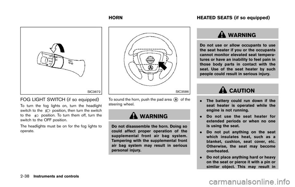
SIC3672
FOG LIGHT SWITCH (if so equipped)
To turn the fog lights on, turn the headlight
switch to theposition, then turn the switch
to theposition. To turn them off, turn the
switch to the OFF position.
The headlights must be on for the fog lights to
operate.
SIC3586
To sound the horn, push the pad area*Aof the
steering wheel.
WARNING
Do not disassemble the horn. Doing so
could affect proper operation of the
supplemental front air bag system.
Tampering with the supplemental front
air bag system may result in serious
personal injury.
WARNING
Do not use or allow occupants to use
the seat heater if you or the occupants
cannot monitor elevated seat tempera-
tures or have an inability to feel pain in
those body parts in contact with the
seat. Use of the seat heater by such
people could result in serious injury.
CAUTION
. The battery could run down if the
seat heater is operated while the
engine is not running.
. Do not use the seat heater for
extended periods or when no one
is using the seat.
. Do not put anything on the seat
which insulates heat, such as a
blanket, cushion, seat cover, etc.
Otherwise, the seat may become
overheated.
. Do not place anything hard or heavy
on the seat or pierce it with a pin or
similar object. This may result in
HORN HEATED SEATS (if so equipped)