Page 10 of 482
JVO0058X
1. Front view camera* (P.4-29)
2. Hood (P.3-25)
3. Windshield wiper and washer— Switch operation (P.2-30)
— Blade replacement (P.8-17)
— Window washer fluid (P.8-13)
4. Moonroof* (P.2-53) 5. Outside mirrors (P.3-35)
- Side view camera* (P.4-29)
6. Power windows (P.2-51)
7. Side turn signal light* — Switch operation (P.2-37)
— Bulb replacement (P.8-27)
8. Roof rack (rail)* (P.2-49) 9. Recovery hook (P.6-16)
10. License plate installation (P.9-11)
11. Fog lights*
— Switch operation (P.2-38)
— Bulb replacement (P.8-27)
12. Headlight and turn signal lights — Switch operation (P.2-33)
— Bulb replacement (P.8-27)
13. Tires — Wheel and tires (P. 8-30, P.9-7)
— Flat tire (P.6-3)
— Tire Pressure Monitoring System (TPMS)
(P.2-14, P.5-3)
14. Doors — Keys (P.3-3)
— Door locks (P.3-5)
— Intelligent Key system (P.3-13)
— Security system (P.2-27)
15. Child safety rear door lock (P.3-9)
16. Sliding doors (P.3-7)
*: if so equipped
Illustrated table of contents0-3
EXTERIOR FRONT
Page 12 of 482
SSI0823
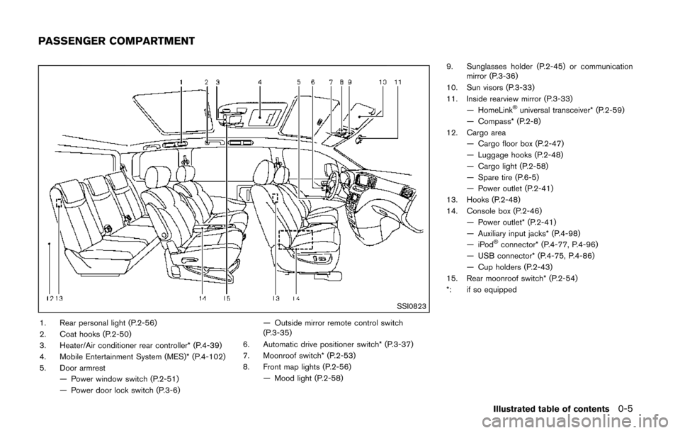
1. Rear personal light (P.2-56)
2. Coat hooks (P.2-50)
3. Heater/Air conditioner rear controller* (P.4-39)
4. Mobile Entertainment System (MES)* (P.4-102)
5. Door armrest— Power window switch (P.2-51)
— Power door lock switch (P.3-6) — Outside mirror remote control switch
(P.3-35)
6. Automatic drive positioner switch* (P.3-37)
7. Moonroof switch* (P.2-53)
8. Front map lights (P.2-56) — Mood light (P.2-58) 9. Sunglasses holder (P.2-45) or communication
mirror (P.3-36)
10. Sun visors (P.3-33)
11. Inside rearview mirror (P.3-33) — HomeLink
®universal transceiver* (P.2-59)
— Compass* (P.2-8)
12. Cargo area — Cargo floor box (P.2-47)
— Luggage hooks (P.2-48)
— Cargo light (P.2-58)
— Spare tire (P.6-5)
— Power outlet (P.2-41)
13. Hooks (P.2-48)
14. Console box (P.2-46) — Power outlet* (P.2-41)
— Auxiliary input jacks* (P.4-98)
—iPod
®connector* (P.4-77, P.4-96)
— USB connector* (P.4-75, P.4-86)
— Cup holders (P.2-43)
15. Rear moonroof switch* (P.2-54)
*: if so equipped
Illustrated table of contents0-5
PASSENGER COMPARTMENT
Page 14 of 482
SSI0824
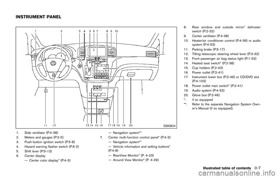
1. Side ventilator (P.4-38)
2. Meters and gauges (P.2-5)
3. Push-button ignition switch (P.5-8)
4. Hazard warning flasher switch (P.6-2)
5. Shift lever (P.5-13)
6. Center display— Center color display* (P.4-3) — Navigation system**
7. Center multi-function control panel* (P.4-3) — Navigation system**
— Vehicle information and setting buttons*
(P.4-8)
— RearView Monitor* (P. 4-23)
— Around View Monitor* (P. 4-29) 8. Rear window and outside mirror* defroster
switch (P.2-32)
9. Center ventilator (P.4-38)
10. Heater/air conditioner control (P.4-39) or audio system (P.4-53)
11. Parking brake (P.5-17)
12. Tilting telescopic steering wheel lever (P.3-32)
13. Front passenger air bag status light (P.1-53)
14. Heated seat switch* (P.2-38)
15. Cup holders (P.2-43)
16. Power outlet (P.2-41)
17. Instrument lower box (P.2-46) or CD/DVD slot (P.4-103)
18. Power outlet main switch* (P.2-41)
19. Audio system (P.4-53)
20. Glove box (P.2-46)
*: if so equipped
**: Refer to the separate Navigation System Own- er’s Manual (if so equipped) .
Illustrated table of contents0-7
INSTRUMENT PANEL
Page 83 of 482
2-4Instruments and controls
SSI0824
1. Side ventilator
2. Meters and gauges
3. Push-button ignition switch
4. Hazard warning flasher switch
5. Shift lever
6. Center display— Center color display* — Navigation system**
7. Center multi-function control panel* — Navigation system**
— Vehicle information and setting buttons*
— RearView Monitor*
— Around View Monitor*
8. Rear window and outside mirror* defroster switch
9. Center ventilator
10. Heater/air conditioner control or audio system
11. Parking brake
12. Tilting telescopic steering wheel lever
13. Front passenger air bag status light
14. Heated seat switch*
15. Cup holders
16. Power outlet
17. Instrument lower box or CD/DVD slot
18. Power outlet main switch*
19. Audio system
20. Glove box
*: if so equipped
**: Refer to the separate Navigation System Own- er’s Manual (if so equipped) .
INSTRUMENT PANEL
Page 115 of 482
2-36Instruments and controls
headlights turn off automatically.
SIC2275
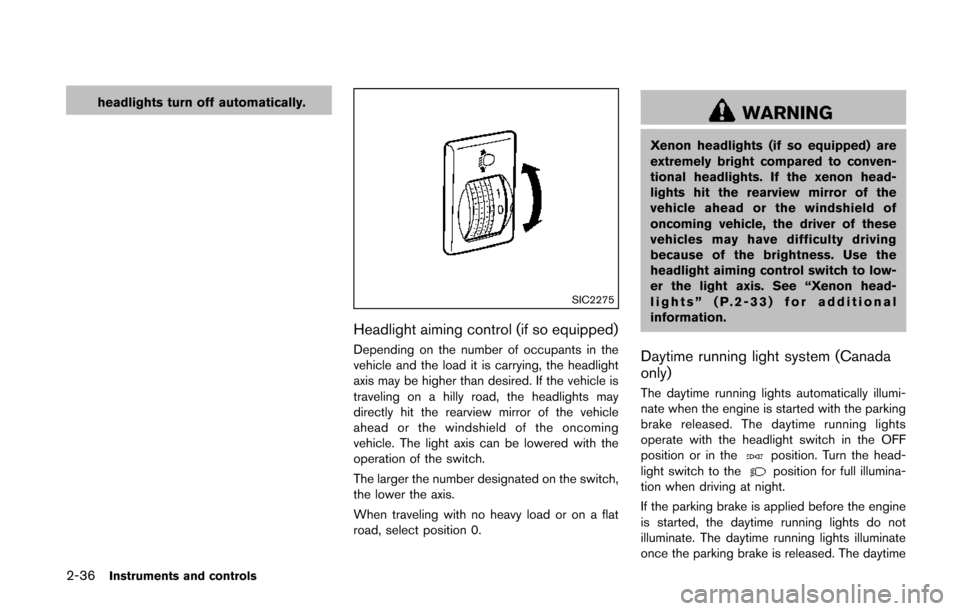
Headlight aiming control (if so equipped)
Depending on the number of occupants in the
vehicle and the load it is carrying, the headlight
axis may be higher than desired. If the vehicle is
traveling on a hilly road, the headlights may
directly hit the rearview mirror of the vehicle
ahead or the windshield of the oncoming
vehicle. The light axis can be lowered with the
operation of the switch.
The larger the number designated on the switch,
the lower the axis.
When traveling with no heavy load or on a flat
road, select position 0.
WARNING
Xenon headlights (if so equipped) are
extremely bright compared to conven-
tional headlights. If the xenon head-
lights hit the rearview mirror of the
vehicle ahead or the windshield of
oncoming vehicle, the driver of these
vehicles may have difficulty driving
because of the brightness. Use the
headlight aiming control switch to low-
er the light axis. See “Xenon head-
lights” (P.2-33) for additional
information.
Daytime running light system (Canada
only)
The daytime running lights automatically illumi-
nate when the engine is started with the parking
brake released. The daytime running lights
operate with the headlight switch in the OFF
position or in the
position. Turn the head-
light switch to theposition for full illumina-
tion when driving at night.
If the parking brake is applied before the engine
is started, the daytime running lights do not
illuminate. The daytime running lights illuminate
once the parking brake is released. The daytime
Page 177 of 482
3-34Pre-driving checks and adjustments
SPA2143
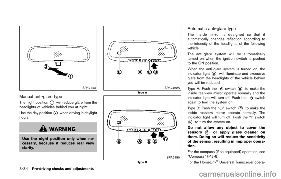
Manual anti-glare type
The night position*1will reduce glare from the
headlights of vehicles behind you at night.
Use the day position
*2when driving in daylight
hours.
WARNING
Use the night position only when ne-
cessary, because it reduces rear view
clarity.
SPA2422AType A
SPA2450Type B
Automatic anti-glare type
The inside mirror is designed so that it
automatically changes reflection according to
the intensity of the headlights of the following
vehicle.
The anti-glare system will be automatically
turned on when the ignition switch is pushed
to the ON position.
When the anti-glare system is turned on, the
indicator light
*Awill illuminate and excessive
glare from the headlights of the vehicle behind
you will be reduced.
Type A: Push the
switch*Bto make the
inside rearview mirror operate normally and the
indicator light will turn off. Push the
switch
again to turn the system on.
Type B: Push the “*” switch
*Cto make the
inside rearview mirror operate normally. The
indicator light will turn off. Push the “I” switch
*Dto turn the system on.
Do not allow any object to cover the
sensors
*Eor apply glass cleaner on
them. Doing so will reduce the sensitivity
of the sensor, resulting in improper opera-
tion.
For the compass (if so equipped) operation, see
“Compass” (P.2-8) .
For the HomeLink
®Universal Transceiver opera-
Page 178 of 482
tion, see “HomeLink®Universal Transceiver”
(P.2-59) .
OUTSIDE MIRRORS
WARNING
Objects viewed in the outside mirror on
the passenger side are closer than they
appear. Be careful when moving to the
right. Using only this mirror could cause
an accident. Use the inside mirror or
glance over your shoulder to properly
judge distances to other objects.
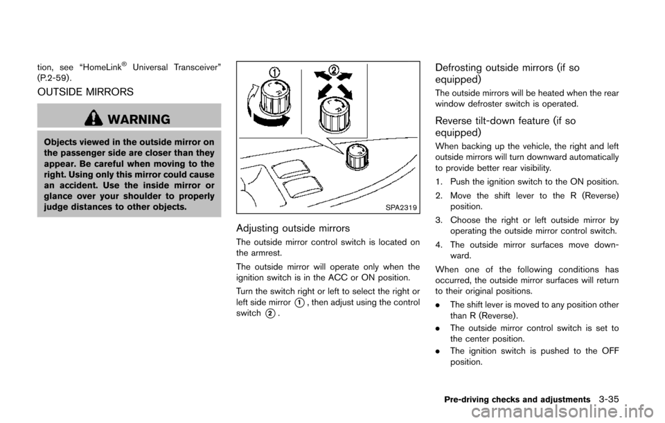
SPA2319
Adjusting outside mirrors
The outside mirror control switch is located on
the armrest.
The outside mirror will operate only when the
ignition switch is in the ACC or ON position.
Turn the switch right or left to select the right or
left side mirror
*1, then adjust using the control
switch
*2.
Defrosting outside mirrors (if so
equipped)
The outside mirrors will be heated when the rear
window defroster switch is operated.
Reverse tilt-down feature (if so
equipped)
When backing up the vehicle, the right and left
outside mirrors will turn downward automatically
to provide better rear visibility.
1. Push the ignition switch to the ON position.
2. Move the shift lever to the R (Reverse) position.
3. Choose the right or left outside mirror by operating the outside mirror control switch.
4. The outside mirror surfaces move down- ward.
When one of the following conditions has
occurred, the outside mirror surfaces will return
to their original positions.
. The shift lever is moved to any position other
than R (Reverse).
. The outside mirror control switch is set to
the center position.
. The ignition switch is pushed to the OFF
position.
Pre-driving checks and adjustments3-35
Page 179 of 482
3-36Pre-driving checks and adjustments
SPA1829
Foldable outside mirrors
Fold the outside mirror by pushing it toward the
rear of the vehicle.
SIC4448
VANITY MIRROR
To use the front vanity mirror, pull down the sun
visor and pull up the cover.
SPA2830
COMMUNICATION MIRROR (if so
equipped)
The communication mirror can be used to view
the second or third row seat inside the vehicle.
To use the communication mirror, push the lid.
To store the mirror, push it in until it latches.