2014 MITSUBISHI OUTLANDER SPORT door lock
[x] Cancel search: door lockPage 4 of 388
![MITSUBISHI OUTLANDER SPORT 2014 3.G Owners Manual Instruments and Controls
Overview 1-2
1
Audio
*
Mitsubishi Multi Communication System (MMCS)
*
[For DISPLAY AUDIO and MMCS, refer to the separate owner’s manuals.]Digital clock
*
Accessory socket
* MITSUBISHI OUTLANDER SPORT 2014 3.G Owners Manual Instruments and Controls
Overview 1-2
1
Audio
*
Mitsubishi Multi Communication System (MMCS)
*
[For DISPLAY AUDIO and MMCS, refer to the separate owner’s manuals.]Digital clock
*
Accessory socket
*](/manual-img/19/7545/w960_7545-3.png)
Instruments and Controls
Overview 1-2
1
Audio
*
Mitsubishi Multi Communication System (MMCS)
*
[For DISPLAY AUDIO and MMCS, refer to the separate owner’s manuals.]Digital clock
*
Accessory socket
* P.8-66
4WD lock switch P.7-19
Glove box P.8-68Card holder P.8-68Passenger’s ventilators P. 8 - 2
Bonnet release lever P. 1 1 - 3
Key slot P.7-13
Fuel tank filler door release lever P.2-13
Parking brake lever P.7-4
Selector lever (Joystick Type) P.7-14
Hazard warning flasher switchP. 6 - 4 5
Air conditioner P.8-4
Rear window demister switch P.6-53Wiper deicer switch* P.6-53
Fuse box P.11-15
Supplemental restraint system (SRS) - airbag (for front passenger’s seat) P.5-23
Floor console box P.8-69ArmrestAccessory socket P.8-66USB input terminal P.8-61
Heated seat switch
* P.5-4
Cup holder P.8-70
Electric tailgate power switch
* P.4-17
BK0203201EN.book 2 ページ 2013年11月19日 火曜日 午前11時50分
Page 5 of 388
Interior1-3 Overview
1
E00100206107
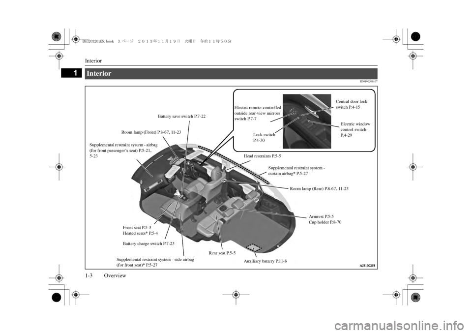
Interior Supplemental restraint system - airbag (for front passenger’s seat) P.5-21, 5-23
Room lamp (Front) P.8-67, 11-23Front seat P.5-3Heated seats
* P.5-4
Supplemental restraint system - side airbag (for front seat)
* P.5-27
Rear seat P.5-5
Supplemental restraint system -curtain airbag
* P.5-27
Armrest P.5-5Cup holder P.8-70
Electric remote-controlled outside rear-view mirrors switch P.7-7
Central door lock switch P.4-15
Lock switch P. 4 - 3 0
Electric window control switch P. 4 - 2 9
Head restraints P.5-5
Battery save switch P.7-22
Battery charge switch P.7-23
Auxiliary battery P.11-8
Room lamp (Rear) P.8-67, 11-23
BK0203201EN.book 3 ページ 2013年11月19日 火曜日 午前11時50分
Page 9 of 388
Outside (Rear)1-7 Overview
1
E00100506764
Outside (Rear)
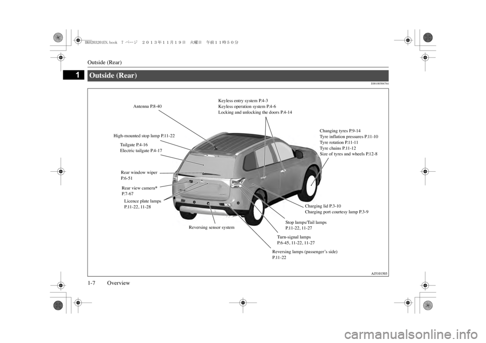
Antenna P.8-40
High-mounted stop lamp P.11-22
Rear window wiperP. 6 - 5 1Rear view camera
*
P. 7 - 6 7Licence plate lamps P.11-22, 11-28
Reversing lamps (passenger’s side) P. 1 1 - 2 2
Stop lamps/Tail lamps P. 1 1 - 2 2 , 1 1 - 2 7
Turn-signal lamps P. 6 - 4 5 , 1 1 - 2 2 , 1 1 - 2 7
Changing tyres P.9-14Ty r e i n f l a t i o n p r e s s u r e s P. 11 -1 0Ty r e r o t a t i o n P. 11 -11Ty r e c h a i n s P. 11 -1 2Size of tyres and wheels P.12-8
Keyless entry system P.4-3Keyless operation system P.4-6Locking and unlocking the doors P.4-14
Ta i l g a t e P. 4 - 1 6Electric tailgate P.4-17
Charging lid P.3-10Charging port courtesy lamp P.3-9
Reversing sensor system
BK0203201EN.book 7 ページ 2013年11月19日 火曜日 午前11時50分
Page 23 of 388
Installation of accessories2-14 General information
2
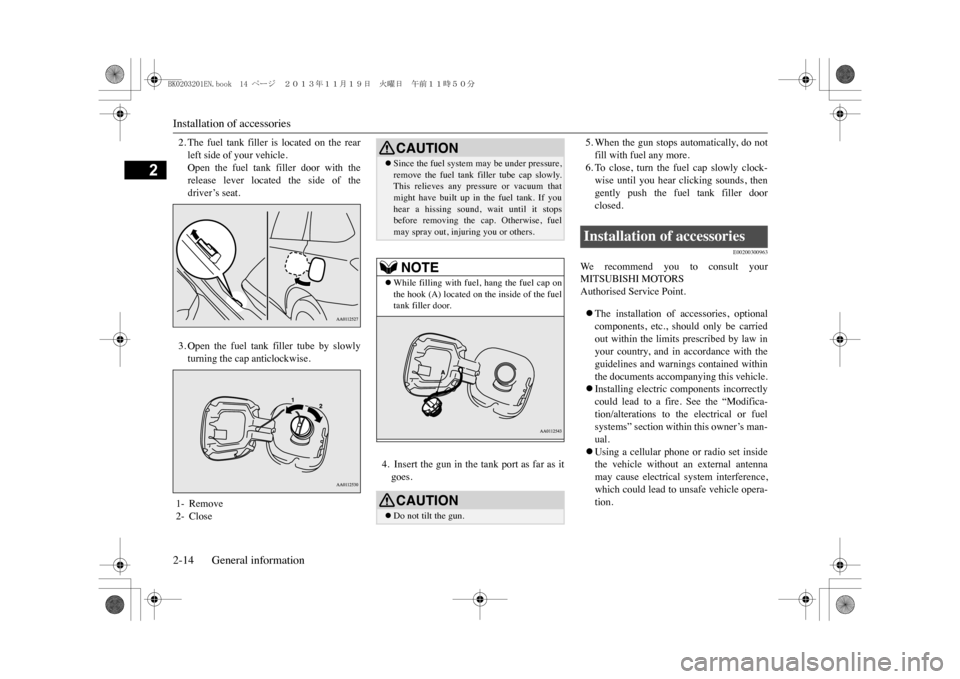
2. The fuel tank filler is located on the rearleft side of your vehicle.Open the fuel tank filler door with therelease lever located the side of thedriver’s seat.3. Open the fuel tank filler tube by slowlyturning the cap anticlockwise.
4. Insert the gun in the tank port as far as itgoes.
5. When the gun stops automatically, do notfill with fuel any more.6. To close, turn the fuel cap slowly clock-wise until you hear clicking sounds, thengently push the fuel tank filler doorclosed.
E00200300963
We r e c o m m e n d y o u t o c o n s u l t y o u rMITSUBISHI MOTORSAuthorised Service Point.�zThe installation of accessories, optionalcomponents, etc., should only be carriedout within the limits prescribed by law inyour country, and in accordance with theguidelines and warnings contained withinthe documents accompanying this vehicle.�zInstalling electric components incorrectlycould lead to a fire. See the “Modifica-tion/alterations to the electrical or fuelsystems” section within this owner’s man-ual.�zUsing a cellular phone or radio set insidethe vehicle without an external antennamay cause electrical system interference,which could lead to unsafe vehicle opera-tion.
1- Remove2- Close
CAUTION�zSince the fuel system
may be under pressure,
remove the fuel tank filler tube cap slowly.This relieves any pressure or vacuum thatmight have built up in the fuel tank. If youhear a hissing sound, wait until it stopsbefore removing the cap. Otherwise, fuelmay spray out, injuring you or others.NOTE
�zWhile filling with fuel, hang the fuel cap onthe hook (A) located on the inside of the fueltank filler door.CAUTION�zDo not tilt the gun.
Installation of accessories
BK0203201EN.book 14 ページ 2013年11月19日 火曜日 午前11時50分
Page 34 of 388
Normal charging (charging method with rated AC 240 V outlet)
Charging 3-9
3
E08304101035
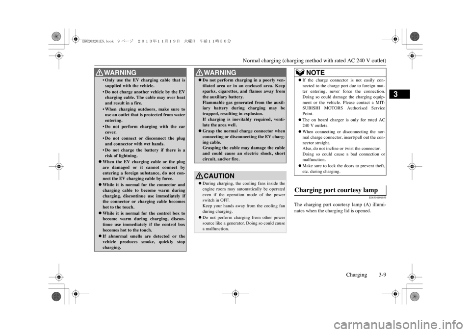
The charging port courtesy lamp (A) illumi-nates when the charging lid is opened.
•Only use the EV charging cable that issupplied with the vehicle.•Do not charge another vehicle by the EVcharging cable. The cable may over heatand result in a fire.•When charging outd
oors, make sure to
use an outlet that is protected from waterentering.•Do not perform charging with the carcover.•Do not connect or disconnect the plugand connector with wet hands.•Do not charge the battery if there is arisk of lightning.
�zWhen the EV charging cable or the plugare damaged or it cannot connect byentering a foreign substance, do not con-nect the EV charging cable by force.�zWhile it is normal for the connector andcharging cable to become warm duringcharging, discontinue use immediately ifthe connector or charging cable becomeshot to the touch.�zWhile it is normal for the control box tobecome warm during
charging, discon-
tinue use immediately if the control boxbecomes hot to the touch.�zIf abnormal smells are detected or thevehicle produces smoke, quickly stopcharging.WA R N I N G
�zDo not perform chargi
ng in a poorly ven-
tilated area or in an
enclosed area. Keep
sparks, cigarettes,
and flames away from
the auxiliary battery.Flammable gas generated from the auxil-iary battery during charging may betrapped, resulting in explosion.If charging is inevitably required, venti-late the area well.�zGrasp the normal charge connector whenconnecting or disconn
ecting the EV charg-
ing cable.Grasping the cable may damage the cableand could cause an electric shock, shortcircuit, and/or fire.CAUTION�zDuring charging, the cooling fans inside theengine room may automatically be operatedeven if the operation mode of the powerswitch in OFF.Keep your hands away from the cooling fanduring charging.�zDo not perform charging from other powersource like a generator. Doing so could causea malfunction.WA R N I N G
NOTE
�zIf the charge connector is not easily con-nected to the charge port due to foreign mat-ter entering, never force the connection.Doing so could damage the charging equip-ment or the vehicle. Please contact a MIT-SUBISHI MOTORS Authorised ServicePoint.�zThe on board charger is only for rated AC240 V outlets.�zWhen connecting or disconnecting the nor-mal charge connector, insert/pull out the con-nector straight.Also, do not incline or twist the connector.Doing so could caus
e a bad connection or
malfunction.�zMake sure to lock the doors to prevent theft,etc. during charging.
Charging port courtesy lamp
BK0203201EN.book 9 ページ 2013年11月19日 火曜日 午前11時50分
Page 38 of 388
Normal charging (charging method with rated AC 240 V outlet)
Charging 3-13
3
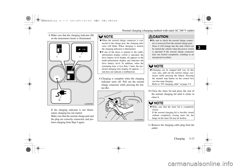
8. Make sure that the charging indicator (H)on the instrument cluster is illuminated.If the charging indicator is not illumi-nated, charging has not started.Make sure that the normal charge port andthe plug are correctly connected, and per-form charging from Step 5 again.
9. Charging is complete when the chargingindicator turns off. Pull out the normalcharge connector while pressing the but-ton (K).
10. Close the inner lid and press the rear of
the normal charging lid until it clicks toclose it.
11. Remove the charging cable plug from the
outlet.
IH
J
NOTE
�zWhen the normal charge connector is con-nected to the charge port, the charging indi-cator will blink. When charging is started,the charging indicator is illuminated.�zIf one of the doors is opened or the multi-information display switch is operated, thedrive battery level display (I) appears in themulti-information disp
lay and indicates the
drive battery level. In addition, when theremaining time is less than 1 hour, the pre-dicted charging time display (J) appears --:--and does not indicate a malfunction.
K
CAUTION�zBe sure to check the normal charge connec-tor is removed from the normal charge port.Since it will change into the state which canbe started the vehicle when the power switchis operated if the normal charge connectordoes not locked completely, resulting in anunexpected accident.NOTE
�zCharging can be stopped half way. In thiscase, also, pull out the normal charge con-nector while pressing the button. Pressingthe manual stop button on the control boxcan also stop charging.Refer to “EV charging cable” on page 3-5.NOTE
�zMake sure that the inner lid is completelyclosed.If the normal charging lid is forcibly closedwithout completely cl
osing inner lid, the
hinge on the inner lid may be broken.
BK0203201EN.book 13 ページ 2013年11月19日 火曜日 午前11時50分
Page 46 of 388
4
Locking and unlockingKeys ..................................................................................................4-2Key number tag ................................................................................4-2Electronic immobilizer (Anti-theft starting system) .........................4-3Keyless entry system ........................................................................4-3Keyless operation system .................................................................4-6Doors...............................................................................................4-14Central door locks ...........................................................................4-15“Child-protection” rear doors .........................................................4-15Ta i l g a t e * . . . . . . . . . . . . . . . . . . . . . . . . . . . . . . . . . . . . . . . . . . . . . . . . . . . . . . . . . . . . . . . . . . . . . . . . . . . . . . . . . . . . . . . . 4 - 1 6Electric tailgate* .............................................................................4-17Inside tailgate release......................................................................4-24Security alarm system * ..................................................................4-24Electric window control ..................................................................4-29Sunroof * ........................................................................................4-31
BK0203201EN.book 1 ページ 2013年11月19日 火曜日 午前11時50分
Page 47 of 388
Keys4-2 Locking and unlocking
4
E00300103572
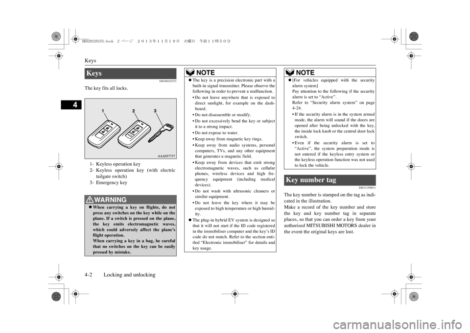
The key fits all locks.
E00312700011
The key number is stamped on the tag as indi-cated in the illustration.Make a record of the key number and storethe key and key number tag in separateplaces, so that you can order a key from yourauthorised MITSUBISHI MOTORS dealer inthe event the original keys are lost.
Keys 1- Keyless operation key2- Keyless operation key (with electric
tailgate switch)
3- Emergency keyWA R N I N G�zWhen carrying a key on flights, do notpress any switches on
the key while on the
plane. If a switch is pressed on the plane,the key emits electromagnetic waves,which could adversely affect the plane’sflight operation.When carrying a key in
a bag, be careful
that no switches on
the key can be easily
pressed by mistake.
NOTE
�zThe key is a precision electronic part with abuilt-in signal transmitter. Please observe thefollowing in order to prevent a malfunction.•Do not leave anywhere
that is exposed to
direct sunlight, for example on the dash-board.•Do not disassem
ble or modify.
•Do not excessively bend the key or subjectit to a strong impact.•Do not expose to water.•Keep away from magnetic key rings.•Keep away from audio systems, personalcomputers, TVs, and any other equipmentthat generates a magnetic field.•Keep away from devices that emit strongelectromagnetic waves, such as cellularphones, wireless de
vices and high fre-
quency equipment (i
ncluding medical
devices).• Do not wash with ultrasonic cleaners orsimilar equipment.•Do not leave the key where it may beexposed to high temperature or high humid-ity.
�zThe plug-in hybrid EV system is designed sothat it will not start if the ID code registeredin the immobiliser computer and the key’s IDcode do not match. Refer to the section enti-tled “Electronic immobiliser” for details andkey usage.
�z[For vehicles equipped with the securityalarm system]Pay attention to the following if the securityalarm is set to “Active”.Refer to “Security alarm system” on page4-24.•If the security alarm is in the system armedmode, the alarm will
sound if the doors are
opened after being unl
ocked with the key,
the inside lock knob or the central door lockswitch.•Even if the security alarm is set to“Active”, the system preparation mode isnot entered if the keyless entry system orthe keyless operation
function was not used
to lock the vehicle.
Key number tag
NOTE
BK0203201EN.book 2 ページ 2013年11月19日 火曜日 午前11時50分