2014 MITSUBISHI OUTLANDER load capacity
[x] Cancel search: load capacityPage 81 of 451

Break-in recommendations
Features and controls 5-3
5
N00508701353
Advanced automobile
manufacturing tech-
niques permit you to operate your new vehi- cle without requiring a long break-in periodof low-speed driving. However, you can add to the future perfor- mance and economy of your vehicle byobserving the following precautions during the first 300 miles (500 km). Drive your vehicle at m
oderate speeds during
the break-in period. Avoid revving the engine. Avoid rough driving such as sudden starts, sudden accelerati
on, prolonged high-
speed driving and sudden braking. These actions would have a detrimental effect onthe engine and lead to increased fuel and oil consumption; th
is could ultimately
result in the malfunction of engine com-ponents. Be particularly careful to avoid full acceleration while in low shift posi- tion (low gears). Do not overload the vehicle. Stay within the seating capacity. (Refer to “Cargo load precautions” on page 6-10.)Do not overload the vehicle. Stay within the seating capacity. (Refer to “Cargo load precautions” on page 6-11.)
Refrain from towing a trailer or other vehicle (Refer to “Trailer towing” on page6-11).
N00508801628
Two keys are provided. The keys fit all locks. Keep one in a safe place as a spare key. Two F.A.S.T.-keys and two emergency keys are provided.
Keep one F.A.S.T.-key and one emergency key in a safe pl
ace together as a set of spare
keys.
Break-in recommendations
Keys Ty p e 1 1- Key for the electronic immobilizer and
keyless entry system
2- Key number plateTy p e 2
1- F.A.S.T.-key
(with electronic im
mobilizer and key-
less entry system function)
2- Emergency key 3- Key number plate
NOTE
The key is a precision
electronic device with
a built-in signal transm
itter. Please observe
the following in order to prevent damage. • Do not leave where it may be exposed to heat caused by direct
sunlight, such as on
top of the dashboard. • Do not take the remote
control transmitter
apart. • Do not excessively bend the key or subject it to strong impacts.
BK0200500US.book 3 ページ 2013年2月12日 火曜日 午前9時46分
Page 163 of 451
Hill start assist (if so equipped) Features and controls 5-85
5
N00517600364
Your vehicle is equipped with power brakes for more braking force with less brake pedal effort.Your brakes are designed to operate at full capacity, even if the power assist is not being used.If the power assist is not being used, the effort needed to press the brake pedal is greater. If you should lose the power assist for somereason, the brakes will still work. If the power brake unit or either of the two brake hydraulic systems stops working prop-erly, the rest of the brake system will still work, but the vehicle will not slow down as quickly.You will know this ha
s happened if you find
you need to press the brake down farther, or harder when slowing down or stopping, or ifthe brake warning light and the warning dis- play in the multi-information display come on.
N00550700124
The disc brakes have an alarm that makes a metallic squeal when
the brake pads have
worn down enough to need service.If you hear this sound, have the brake pads replaced at an authorized Mitsubishi Motors dealer or a repair facility of your choice.
N00562601097
The hill start assist make
s it easy to start off
on a steep uphill slope by preventing thevehicle from moving back
wards. It keeps the
braking force for about 2 second when you move your foot from the brake pedal to theaccelerator pedal.
CAUTION It is important not to drive the vehicle with your foot resting on the brake pedal whenbraking is not required. This practice canresult in very high brake temperatures, pre- mature lining wear, a
nd possible damage to
the brakes.
Power brakes
WA R N I N G Never coast downhill
with the engine OFF.
Keep the engine running whenever yourvehicle is in motion. If you turn off theengine while driving, the power brake booster will stop wo
rking and your brakes
will not work as well. If the power assist is lost or if either brake hydraulic system stops working properly,take your vehicle to
an authorized Mit-
subishi Motors dealer or a repair facility of your choice immediately.
Brake pad wear alarm
WA R N I N G Driving with worn brake pads will make it harder to stop, and can cause an accident.
Hill start assist
(if so equipped)
CAUTION Do not overly rely on the hill start assist to prevent backwards movement of the vehicle.Under certain circumstan
ces, even when hill
start assist is activated, the vehicle may move backwards if the brake pedal is not suf-ficiently depressed, if the vehicle is heavily loaded, or if the road is very steep or slip- pery. The hill start assist is
not designed to keep
the vehicle stopped in place on uphill slopesfor more than 2 seconds. When facing uphill, do not rely on using the hill start assist to
maintain a stopped position
as an alternative to depressing the brake pedal.Doing so could cause an accident. Do not turn the ignition switch to the “OFF”, “LOCK” or “ACC” po
sition while the hill
start assist is operating. The hill start assist could stop operating,
which could result in
an accident.
BK0200500US.book 85 ページ 2013年2月12日 火曜日 午前9時46分
Page 307 of 451

Loading information Driving safety 6-7
6
Vehicle maximum load on the tire: load on an individual tire that is determined bydistributing to each axle its share of the maximum loaded vehicle weight and dividing by two. Vehicle normal load on the tire: load on an individual tire that is determined by dis- tributing to each axle its share of the curbweight, accessory weight, and normal occupant weight and dividing by two. Maximum loaded vehicle weight: the sum of - (a) Curb weight;(b) Accessory weight; (c) Vehicle capacity weight; and (d) Production options weight. Curb weight: the weight of a motor vehi- cle with standard e
quipment including the
maximum capacity of fuel, oil, and cool-ant. Accessory weight: the combined weight (in excess of those
standard items which
may be replaced) of automatic transmis- sion, power steering, power brakes, power windows, power seats, radio, and heater,to the extent that these items are available as factory- installed equipment (whether installed or not). Vehicle capacity weight: the rated cargo and luggage load plus 150 lbs (68 kg) * times the vehicle’s
designated seating
capacity.
Production options weight: the combined weight of those installed regular produc-tion options weighing over 5 lbs (2.3 kg) in excess of those standard items which they replace, not prev
iously considered in
curb weight or accessory weight, includ- ing heavy duty brakes,
ride levelers, roof
rack, heavy duty battery, and special trim. Normal occupant weight: 150 lbs (68 kg) * times the number of
specified occupants
(3 in the case of your vehicle) Occupant distribution:
Occupant distribu-
tion within the passenger compartment (Inyour vehicle the distribution is 2 in front, 1 in second row seat)
N00630101407
The tire and loading information placard is located on the inside sill of the driver’s door.
This placard shows the maximum number of occupants permitted to
ride in your vehicle as
well as “the combined
weight of occupants
and cargo” (A), which
is called the vehicle
capacity weight. The weight of any non-fac-tory installed options, as well as the tongue weight of a trailer being towed and roof load is included in the defi
nition of “cargo” when
determining the vehicle
capacity weight. This
placard also tells you the size and recom- mended inflation pressure for the originalequipment tires on your vehicle. For more information, refer to
“Tires” on page 9-14.
* :150 lbs (68 kg) is th
e weight of one per-
son as defined by U.S.A. and Canadian regulations.
Tire and loading information placard
BK0200500US.book 7 ページ 2013年2月12日 火曜日 午前9時46分
Page 308 of 451
Loading information 6-8 Driving safety
6
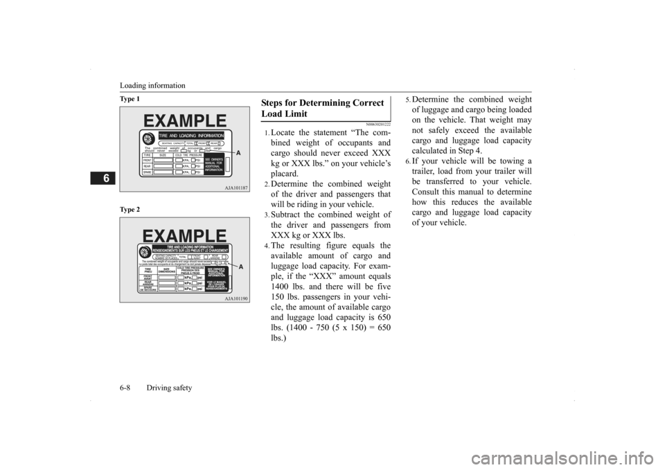
Ty p e 1 Ty p e 2
N00630201222
1.Locate the statement “The com- bined weight of occupants and cargo should never exceed XXX kg or XXX lbs.” on your vehicle’splacard.2.Determine the combined weightof the driver and passengers thatwill be riding in your vehicle.3.Subtract the combined weight ofthe driver and passengers fromXXX kg or XXX lbs.4.The resulting figure equals theavailable amount of cargo andluggage load capacity. For exam- ple, if the “XXX” amount equals 1400 lbs. and there will be five150 lbs. passengers in your vehi- cle, the amount of available cargo and luggage load
capacity is 650
lbs. (1400 - 750 (5 x 150) = 650lbs.)
5.Determine the combined weightof luggage and cargo being loaded on the vehicle. That weight may not safely exceed the availablecargo and luggage load capacity calculated in Step 4.6.If your vehicle will be towing a trailer, load from your trailer will be transferred to your vehicle. Consult this manual to determinehow this reduces the available cargo and luggage load capacity of your vehicle.
Steps for Determining Correct Load Limit
BK0200500US.book 8 ページ 2013年2月12日 火曜日 午前9時46分
Page 309 of 451
Loading information Driving safety 6-9
6
NOTE
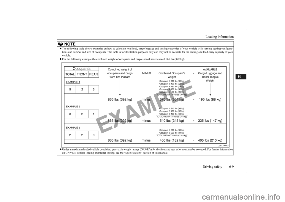
The following table shows examples on how to
calculate tota
l load, cargo/luggage and towing capa
cities of your vehicle with var
ying seating configura-
tions and number and size of occ
upants. This table is for illu
stration purposes only and may not
be accurate for the seating an
d load carry capacity of your
vehicle. For the following example the combined weight of oc
cupants and cargo should ne
ver exceed 865 lbs (392 kg).
Under a maximum loaded vehicle c
ondition, gross axle weight ratings (GAWR’s) for
the front and rear axles must not be exceeded.
For further information
on GAWR’s, vehicle loading and tr
ailer towing, see the “Specifica
tions” section of this manual.
BK0200500US.book 9 ページ 2013年2月12日 火曜日 午前9時46分
Page 310 of 451
Cargo loads 6-10 Driving safety
6
N00629700435 N00630301092
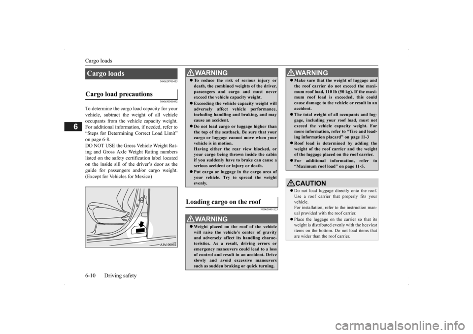
To determine the cargo load capacity for your vehicle, subtract the
weight of all vehicle
occupants from the vehi
cle capacity weight.
For additional information, if needed, refer to “Steps for Determining Correct Load Limit” on page 6-8. DO NOT USE the Gross Vehicle Weight Rat- ing and Gross Axle Weight Rating numberslisted on the safety certification label located on the inside sill of the driver’s door as the guide for passengers and/or cargo weight.(Except for Vehicles for Mexico)
N00630401123
Cargo loads Cargo load precautions
WA R N I N G To reduce the risk of serious injury or death, the combined weights of the driver,passengers and cargo and must neverexceed the vehicle capacity weight. Exceeding the vehicle capacity weight will adversely affect ve
hicle performance,
including handling and braking, and may cause an accident. Do not load cargo or luggage higher than the top of the seatback. Be sure that yourcargo or luggage cann
ot move when your
vehicle is in motion. Having either the re
ar view blocked, or
your cargo being thrown
inside the cabin
if you suddenly have to brake can cause a serious accident or
injury or death.
Put cargo or luggage in the cargo area of your vehicle. Try to spread the weightevenly.
Loading cargo on the roof
WA R N I N G Weight placed on the
roof of the vehicle
will raise the vehicle’
s center of gravity
and adversely affect
its handling charac-
teristics. As a result, driving errors oremergency maneuvers could lead to a loss of control and result in an accident. Drive slowly and avoid excessive maneuverssuch as sudden brak
ing or quick turning.
Make sure that the
weight of luggage and
the roof carrier do not exceed the maxi-mum roof load, 110 lb (50 kg). If the maxi-mum roof load is ex
ceeded, this could
cause damage to the ve
hicle or result in an
accident. The total weight of all occupants and lug- gage, including your r
oof load, must not
exceed the vehicle capacity weight. For more information, refer to “Tire and load- ing information placard” on page 11-3 Roof load is determined by adding the weight of the roof
carrier and the weight
of the luggage placed
on the roof carrier.
For additional information, refer to “Maximum roof load” on page 11-5.CAUTION Do not load luggage directly onto the roof. Use a roof carrier that properly fits your vehicle. For installation, refer to the instruction man-ual provided with the roof carrier. Place the luggage on the carrier so that its weight is distri
buted evenly with the heaviest
items on the bottom. Do not load items that are wider than the roof carrier.WA R N I N G
BK0200500US.book 10 ページ 2013年2月12日 火曜日 午前9時46分
Page 311 of 451
Trailer towing
Driving safety 6-11
6
N00630601112
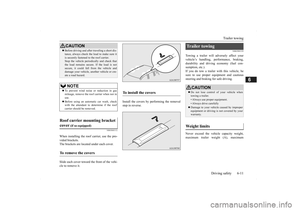
When installing the roof carrier, use the pro- vided brackets. The brackets are located under each cover. Slide each cover toward
the front of the vehi-
cle to remove it.
Install the covers by performing the removal step in reverse.
N00629801329
Towing a trailer will adversely affect your vehicle’s handling, performance, braking, durability and driving economy (fuel con-sumption, etc.). If you do tow a trailer
with this vehicle, be
sure to use proper e
quipment and cautious
steering and braking for safe driving. Never exceed the vehi
cle capacity weight,
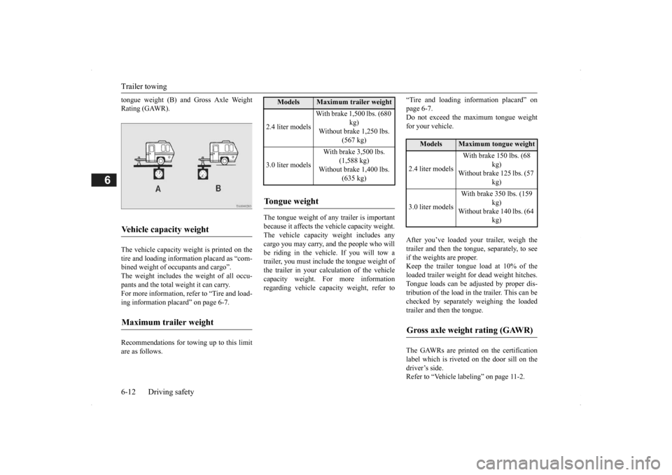
maximum trailer weight (A), maximum
Before driving and after traveling a short dis- tance, always check the load to make sure itis securely fastened to the roof carrier.Stop the vehicle periodi
cally and check that
the load remains secure. If the load is not secure, it could fall from the vehicle anddamage your vehicle,
another vehicle or cre-
ate a road hazard.NOTE
To prevent wind noise or reduction in gas mileage, remove the roof carrier when not in use. Before using an automatic car wash, check with the attendant to determine if the roofcarrier should be removed.
Roof carrier mounting bracket cover
(if so equipped)
To remove the covers
CAUTION
To install the covers
Trailer towing
CAUTION Do not lose control of your vehicle when towing a trailer.• Always use proper equipment.• Always drive carefully Damage to your vehicle caused by improper equipment or driving is not covered by your warranty.
Weight limits
BK0200500US.book 11 ページ 2013年2月12日 火曜日 午前9時46分
Page 312 of 451
Trailer towing 6-12 Driving safety
6
tongue weight (B) and Gross Axle Weight Rating (GAWR). The vehicle capacity weight is printed on the tire and loading inform
ation placard as “com-
bined weight of oc
cupants and cargo”.
The weight includes the weight of all occu- pants and the total weight it can carry.For more information, refer to “Tire and load- ing information plac
ard” on page 6-7.
Recommendations for towing up to this limit are as follows.
The tongue weight of any trailer is important because it affects the vehicle capacity weight. The vehicle capacity weight includes anycargo you may carry, and the people who will be riding in the vehicl
e. If you will tow a
trailer, you must include the tongue weight ofthe trailer in your calc
ulation of the vehicle
capacity weight. For more information regarding vehicle capa
city weight, refer to
“Tire and loading information placard” on page 6-7.Do not exceed the maximum tongue weight for your vehicle. After you’ve loaded your trailer, weigh the trailer and then the to
ngue, separately, to see
if the weights are proper. Keep the trailer tongue load at 10% of theloaded trailer weight fo
r dead weight hitches.
Tongue loads can be adjusted by proper dis- tribution of the load in the trailer. This can bechecked by separately weighing the loaded trailer and then the tongue. The GAWRs are printed on the certification label which is riveted on the door sill on the driver’s side.Refer to “Vehicle labeling” on page 11-2.
Vehicle capacity weight Maximum trailer weight
Models
Maximum trailer weight
2.4 liter models
With brake 1,500 lbs. (680
kg)
Without brake 1,250 lbs.
(567 kg)
3.0 liter models
With brake 3,500 lbs.
(1,588 kg)
Without brake 1,400 lbs.
(635 kg)
Tongue weight
Models
Maximum tongue weight
2.4 liter models
With brake 150 lbs. (68
kg)
Without brake 125 lbs. (57
kg)
3.0 liter models
With brake 350 lbs. (159
kg)
Without brake 140 lbs. (64
kg)
Gross axle weight rating (GAWR)
BK0200500US.book 12 ページ 2013年2月12日 火曜日 午前9時46分