2014 MITSUBISHI LANCER SPORTBACK heater
[x] Cancel search: heaterPage 295 of 422
Automatic air conditioning with
Celsius scale (if so equipped)
7-24 Comfort controls
7
N00731700286
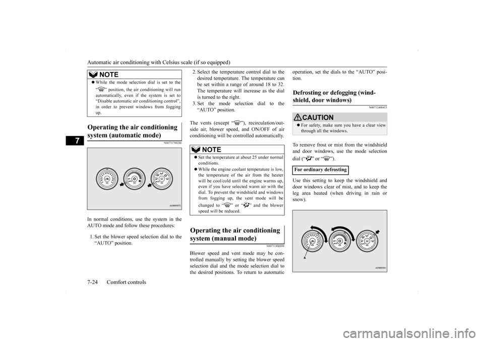
In normal conditions, use the system in the AUTO mode and follow these procedures: 1. Set the blower speed selection dial to the “AUTO” position.
2. Select the temperature control dial to the desired temperature. The temperature can be set within a range of around 18 to 32. The temperature will increase as the dialis turned to the right. 3. Set the mode selection dial to the “AUTO” position.
The vents (except “ ”), recirculation/out- side air, blower speed, and ON/OFF of airconditioning will be controlled automatically.
N00731800098
Blower speed and vent mode may be con-trolled manually by setting the blower speed selection dial and the mode selection dial to the desired positions. To return to automatic
operation, set the dials to the “AUTO” posi- tion.
N00732400453
To remove frost or mist from the windshield and door windows, use
the mode selection
dial (“ ” or “ ”). Use this setting to keep the windshield and door windows clear of mist, and to keep the leg area heated (when driving in rain or snow).
While the mode selection dial is set to the “ ” position, the air conditioning will run automatically, even if the system is set to “Disable automatic air conditioning control”,in order to prevent windows from fogging up.
Operating the air conditioning system (automatic mode)
NOTE
NOTE
Set the temperature at about 25 under normal conditions. While the engine coolant temperature is low, the temperature of the air from the heater will be cool/cold until the engine warms up,even if you have selected warm air with the dial. To prevent the windshield and windows from fogging up, the vent mode will be changed to “ ” or “ ” and the blower speed will be reduced.
Operating the air conditioning system (manual mode)
Defrosting or defogging (wind- shield, door windows)
CAUTION For safety, make sure you have a clear view through all the windows.
For ordinary defrosting
BK0200700US.bo
ok 24 ページ 2013年2月15日 金曜日 午後12時17分
Page 301 of 422
Handling of Discs 7-30 Comfort controls
7
Fingerprints or other marks on the read surface of the disc may result in its con- tent being more difficult to read. When holding the disc, grip both edges, or oneedge and the center hole, in order that the read surface is not touched. Do not affix paper or stickers, or other- wise damage the disc. Do not forcefully insert a disc if another is already within the device. This can resultin damage to discs, or malfunction. Periodically clean the read surface of the disc. When cleaning, do not wipe in a cir- cular motion. Instead, wipe gently out- wards from the center of the disc to theouter edge. New discs may have burring around the outer edge or in the hole in the center.Ensure you check for these. If there are burrs, these may lead to faulty operation, therefore ensure these are removed. When not using discs, ensure these are kept in cases, and stored out of direct sun- light.
If discs are not going to be used for a long period of time, remove these from the product.
In cold environments such as in mid-winter when the interior of the vehicle is cold, turn-ing the heater on and immediately trying to use the product may cause condensation (water droplets) to form
on the disc and inter-
nal optical components, and this may preventthe product from operating correctly. In these conditions, remove the disc, and wait a short time before use. Actions such as unauthorized reproduction, broadcast, public performance, or rental of discs that comprise other than personal use are prohibited by law.
N00715500026
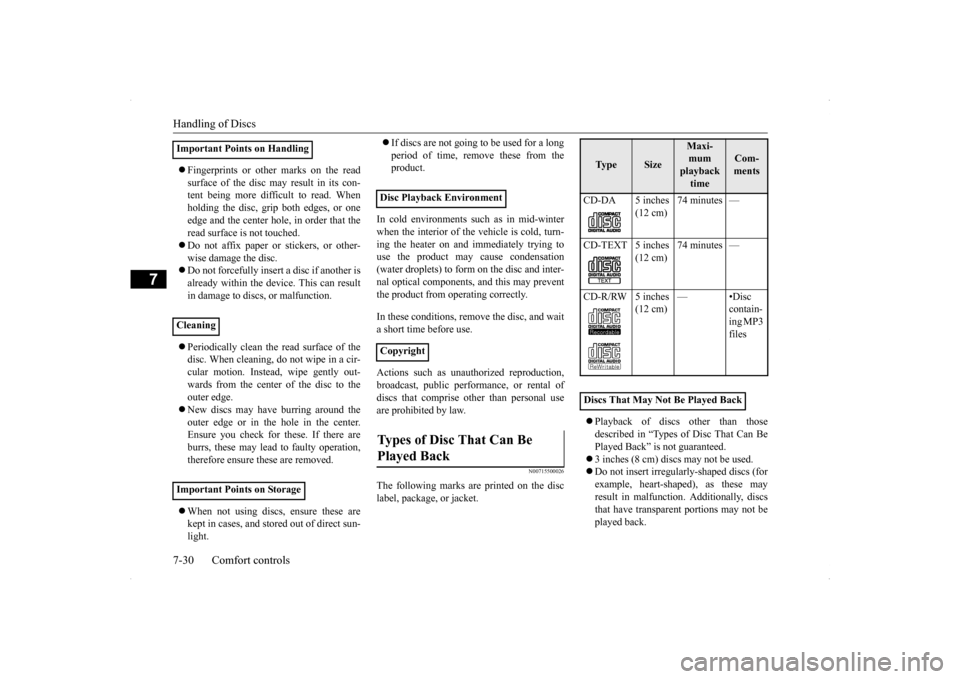
The following marks are printed on the disclabel, package, or jacket.
Playback of discs other than those described in “Types of Disc That Can Be Played Back” is not guaranteed. 3 inches (8 cm) discs may not be used. Do not insert irregularly-shaped discs (for example, heart-shaped), as these may result in malfunction. Additionally, discsthat have transparent portions may not be played back.
Important Points on Handling Cleaning Important Points on Storage
Disc Playback Environment CopyrightTypes of Disc That Can Be Played Back
Ty p e
Size
Maxi- mum playback time
Com-ments
CD-DA 5 inches
(12 cm)
74 minutes —
CD-TEXT 5 inches
(12 cm)
74 minutes —
CD-R/RW 5 inches
(12 cm)
—•Disc
contain- ing MP3 files
Discs That May Not Be Played Back
BK0200700US.bo
ok 30 ページ 2013年2月15日 金曜日 午後12時17分
Page 335 of 422
If the vehicle breaks down 8-2 For emergencies
8
N00836300204
If your vehicle breaks down on the road, move to the shoulder and turn on the hazardwarning flashers. If there is no shoulder, or the shoulder is not safe, drive in the right lane slowly, with the hazard lights flashing, untilyou come to a safe stopping place. Keep the flashers flashing. If the engine stops, there will be no power assist to the steering and brakes, making these difficult to use. The brake booster will not work, so the brakes will not grip well. The brake pedalwill be harder to press than usual. Since there is no power steering assist, the steering wheel will be hard to turn.
Get help from your passengers, bystanders, etc. to push the vehicl
e and move it to a safe
zone.
N00836400654
If the engine cannot be started because the battery is weak or dead, you can start it withthe battery from another vehicle using jumper cables. 1. Take off any metal jewelry such as watch bands or bracelets that might make an accidental electrical contact.
2. Position the vehicles close enough together so that the jumper cables can reach, but be sure the vehicles aren’t touching each other. 3. You could be injured if the vehicles move. Set the parking brake firmly on each vehi- cle. Put an automatic transaxle, CVT or Twin Clutch SST in “P” (PARK) or amanual transaxle in “N” (Neutral). Turn the ignition switch to the “LOCK” posi- tion.
If the vehicle breaks down If the engine stops/fails When the engine fails at the intersection
Jump-starting the engine
WA R N I N G When using jumper cables to start a vehi- cle, follow the procedures and be very cau- tious. CAUTION Do not try to start your vehicle by pushing or towing. Vehicles equipped with continuously variable transmission (CVT) or Twin Clutch SST cannot be started this way. Pushing ortowing a vehicle that has a manual transaxle may overheat and damage the catalytic con- verter. Also, there is more risk of an accidentwhen a vehicle is being pushed or towed.
CAUTION Check the other vehicle. It must have a 12- volt battery. If the other system isn’t 12-volt, both systems can be damaged.WA R N I N G Turn the ignition switch to the “LOCK” position on both vehicles. Make sure thatthe cables or your clothes cannot be caught by the fan or drive belt. Personal injury could result. NOTE
Turn off all lights, heater, and other electrical loads. This will avoid sparks and help saveboth batteries.
BK0200700US.bo
ok 2 ページ 2013年2月15日 金曜日 午後12時17分
Page 378 of 422
Fuses
Vehicle care and maintenance 9-29
9
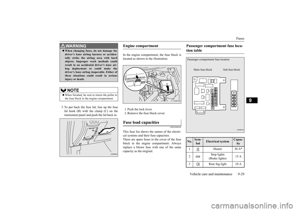
3. To put back the fuse lid, line up the fuse lid hook (B) with the clamp (C) on theinstrument panel and push the lid back in.
In the engine compartment, the fuse block is located as shown in the illustration. 1. Push the lock lever. 2. Remove the fuse block cover.
N00954800244
This fuse list shows the names of the electri- cal systems and their fuse capacities. There are spare fuses in the cover of the fuseblock in the engine compartment. Always replace a blown fuse with one of the same capacity as the original.
WA R N I N G When changing fuses, do not damage the driver’s knee airbag harness or acciden- tally strike the airbag area with hard objects. Improper work methods could result in an accidental driver’s knee air-bag deployment or could make the driver’s knee airbag inoperable. Either of these situations could result in seriousinjury or death.NOTE
When finished, be sure to return the puller to the fuse block in the engine compartment.
Engine compartment Fuse load capacities
Passenger compartment fuse loca- tion table No.
Sym- bol
Electrical system
Capac-ity
1 Heater 30 A
*
2
Stop lights (Brake lights)
15 A
3 Rear fog light 10 APassenger compartme
nt fuse location
Main fuse block
Sub fuse block
BK0200700US.bo
ok 29 ページ 2013年2月15日 金曜日 午後12時17分
Page 380 of 422
Fuses
Vehicle care and maintenance 9-31
9
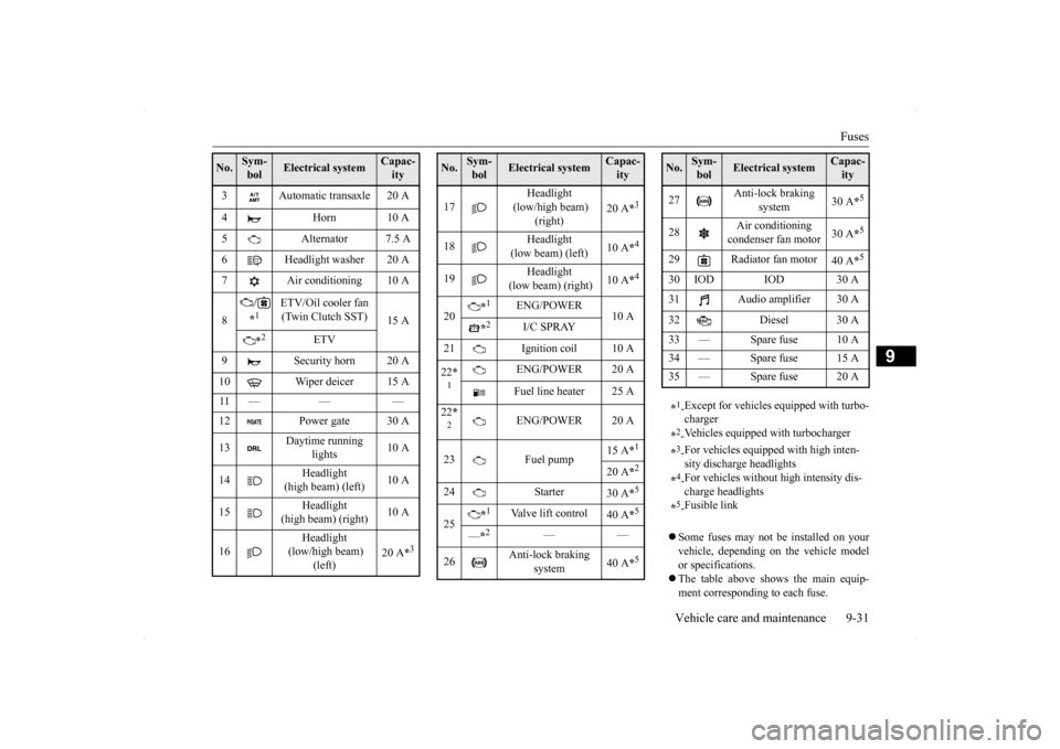
Some fuses may not be installed on your vehicle, depending on the vehicle model or specifications. The table above shows the main equip- ment corresponding to each fuse.
3 Automatic transaxle 20 A 4 Horn 10 A 5 Alternator 7.5 A 6 Headlight washer 20 A 7 Air conditioning 10 A 8
*1
ETV/Oil cooler fan (Twin Clutch SST)
15 A
*2
ETV
9 Security horn 20 A 10 Wiper deicer 15 A 11 — — — 12 Power gate 30 A 13
Daytime running
lights
10 A
14
Headlight
(high beam) (left)
10 A
15
Headlight
(high beam) (right)
10 A
16
Headlight
(low/high beam)
(left)
20 A
*3
No.
Sym- bol
Electrical system
Capac-ity
17
Headlight
(low/high beam)
(right)
20 A
*3
18
Headlight
(low beam) (left)
10 A
*4
19
Headlight
(low beam) (right)
10 A
*4
20
*1
ENG/POWER
10 A
*2
I/C SPRAY
21 Ignition coil 10 A 22 *1
ENG/POWER 20 A Fuel line heater 25 A
22 *2
ENG/POWER 20 A
23 Fuel pump
15 A
*1
20 A
*2
24 Starter
30 A
*5
25
*1
Valve lift control
40 A
*5
—*2
——
26
Anti-lock braking
system
40 A
*5
No.
Sym- bol
Electrical system
Capac-ity
27
Anti-lock braking
system
30 A
*5
28
Air conditioning condenser fan motor
30 A
*5
29 Radiator fan motor
40 A
*5
30 IOD IOD 30 A 31 Audio amplifier 30 A 32 Diesel 30 A 33 — Spare fuse 10 A 34 — Spare fuse 15 A35 — Spare fuse 20 A *1- Except for vehicles equipped with turbo- charger
*2- Vehicles equipped with turbocharger
*3- For vehicles equipped with high inten- sity discharge headlights
*4- For vehicles without high intensity dis- charge headlights
*5- Fusible link
No.
Sym- bol
Electrical system
Capac-ity
BK0200700US.bo
ok 31 ページ 2013年2月15日 金曜日 午後12時17分