2014 MITSUBISHI LANCER SPORTBACK lock
[x] Cancel search: lockPage 215 of 422
Combination headlights and dimmer switch 5-148 Features and controls
5
N00549800167
If the driver’s door is opened with the key in the “LOCK” or “ACC” position or removed
from the ignition switch while the lights are on, the buzzer will sound to remind you to turn off the lights. If the driver’s door is opened with the ignition switch in the “LOCK” or “ACC” position, or if the ignition switch is moved to the “LOCK” position while the lights are on, thebuzzer will sound to remind you to turn offthe lights. In either case, the lights and buzzer will turn off automatically. Or you can turn the light
switch to the “OFF”
position to stop the buzzer.
N00549900155
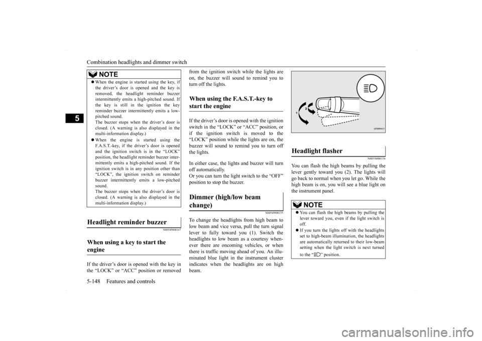
To change the headlights from high beam to low beam and vice versa, pull the turn signal lever to fully toward you (1). Switch theheadlights to low beam as a courtesy when- ever there are oncoming vehicles, or when there is traffic moving ahead of you. An illu-minated blue light in the instrument cluster indicates when the headlights are on high beam.
N00550000156
You can flash the high beams by pulling thelever gently toward you (2). The lights will go back to normal when you let go. While the high beam is on, you will see a blue light onthe instrument panel.
NOTE
When the engine is started using the key, if the driver’s door is opened and the key is removed, the headlight reminder buzzer intermittently emits a high-pitched sound. If the key is still in the ignition the keyreminder buzzer intermittently emits a low- pitched sound. The buzzer stops when the driver’s door isclosed. (A warning is also displayed in the multi-information display.) When the engine is started using the F.A.S.T.-key, if the driver’s door is opened and the ignition switch is in the “LOCK”position, the headlight reminder buzzer inter- mittently emits a high-pitched sound. If the ignition switch is in any position other than“LOCK”, the ignition switch on reminder buzzer intermittently emits a low-pitched sound.The buzzer stops when the driver’s door is closed. (A warning is also displayed in the multi-information display.)
Headlight reminder buzzer When using a key to start the engine
When using the F.A.S.T.-key to start the engine Dimmer (high/low beam change)
Headlight flasher
NOTE
You can flash the high beams by pulling the lever toward you, even if the light switch is off. If you turn the lights off with the headlights set to high-beam illumin
ation, the headlights
are automatically returned to their low-beam setting when the light switch is next turned to the “ ” position.
BK0200700US.book
148 ページ 2013年2月15日 金曜日 午後12時17分
Page 216 of 422
Combination headlights and dimmer switch
Features and controls 5-149
5
N00563201146
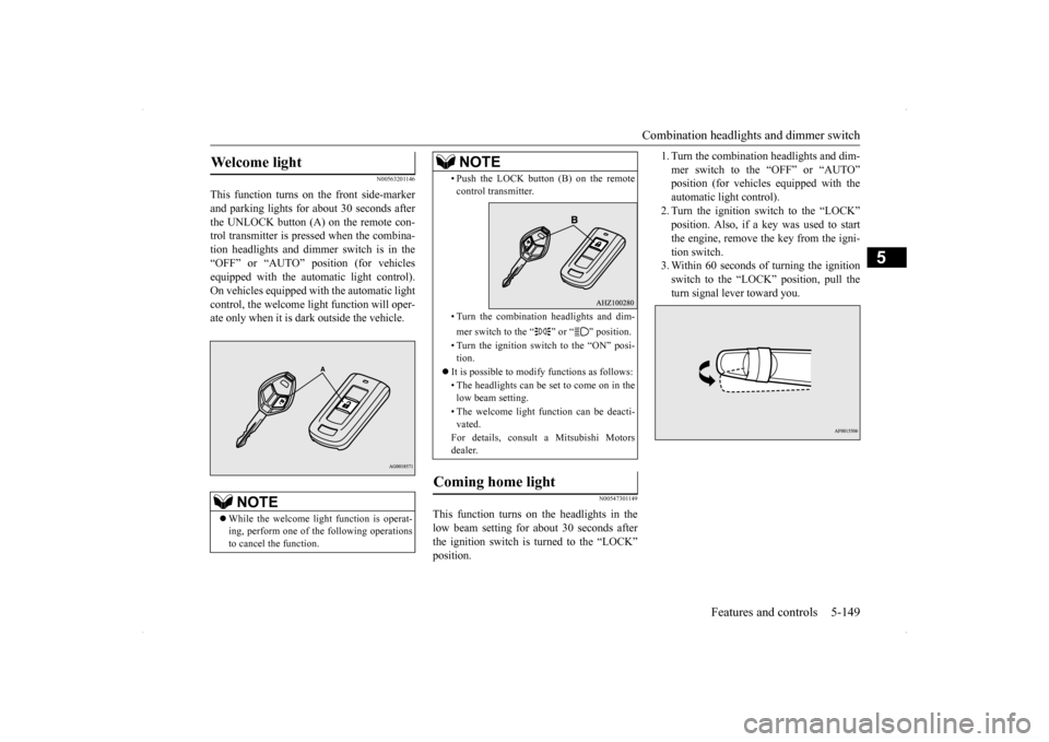
This function turns on the front side-marker and parking lights for about 30 seconds afterthe UNLOCK button (A) on the remote con- trol transmitter is pressed when the combina- tion headlights and dimmer switch is in the“OFF” or “AUTO” position (for vehicles equipped with the automatic light control). On vehicles equipped with the automatic lightcontrol, the welcome light function will oper-ate only when it is dark outside the vehicle.
N00547301149
This function turns on the headlights in thelow beam setting for about 30 seconds afterthe ignition switch is turned to the “LOCK”position.
1. Turn the combination headlights and dim- mer switch to the “OFF” or “AUTO” position (for vehicles equipped with the automatic light control).2. Turn the ignition switch to the “LOCK” position. Also, if a key was used to start the engine, remove the key from the igni-tion switch. 3. Within 60 seconds of turning the ignition switch to the “LOCK” position, pull theturn signal lever toward you.
Welcome light
NOTE
While the welcome light function is operat- ing, perform one of
the following operations
to cancel the function.
• Push the LOCK button (B) on the remote control transmitter. • Turn the combination headlights and dim- mer switch to the “ ” or “ ” position. • Turn the ignition switch to the “ON” posi- tion.
It is possible to modify functions as follows: • The headlights can be set to come on in the low beam setting. • The welcome light function can be deacti- vated. For details, consult a Mitsubishi Motors dealer.
Coming home light
NOTE
BK0200700US.book
149 ページ 2013年2月15日 金曜日 午後12時17分
Page 217 of 422
Headlight leveling switch (if so equipped) 5-150 Features and controls
5
4. The headlights will come on in the low beam setting for about 30 seconds. After the headlights go off, the headlights can be turned on again in the low beam settingfor about 30 seconds by pulling the turn signal lever toward you within 60 seconds of turning the ignition switch to the“LOCK” position. To turn on the head- lights again after 60 seconds of turning the ignition switch to the “LOCK” posi-tion, repeat the process from step 1.
N00537100062
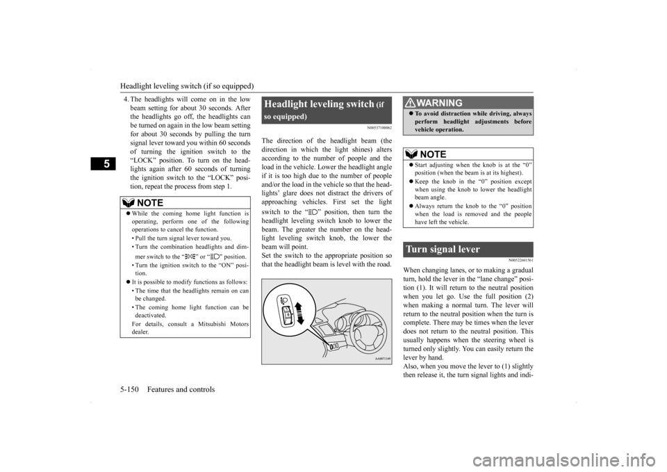
The direction of the headlight beam (thedirection in which the light shines) alters according to the number of people and the load in the vehicle. Lower the headlight angleif it is too high due to the number of people and/or the load in the vehicle so that the head- lights’ glare does not distract the drivers ofapproaching vehicles. First set the light switch to the “ ” position, then turn the headlight leveling switch knob to lower the beam. The greater the number on the head-light leveling switch knob, the lower the beam will point. Set the switch to the appropriate position sothat the headlight beam is level with the road.
N00522601561
When changing lanes, or to making a gradual turn, hold the lever in the “lane change” posi- tion (1). It will return to the neutral positionwhen you let go. Use the full position (2) when making a normal turn. The lever will return to the neutral position when the turn iscomplete. There may be times when the lever does not return to the neutral position. This usually happens when the steering wheel isturned only slightly. You can easily return the lever by hand. Also, when you move the lever to (1) slightlythen release it, the turn signal lights and indi-
NOTE
While the coming home light function is operating, perform one of the followingoperations to cancel the function. • Pull the turn signal lever toward you.• Turn the combination headlights and dim- mer switch to the “ ” or “ ” position. • Turn the ignition switch to the “ON” posi- tion.
It is possible to modify functions as follows: • The time that the headlights remain on can be changed. • The coming home light function can be deactivated. For details, consult a Mitsubishi Motors dealer.
Headlight leveling switch
(if
so equipped)
WA R N I N G To avoid distraction while driving, always perform headlight adjustments before vehicle operation.NOTE
Start adjusting when the knob is at the “0” position (when the beam is at its highest). Keep the knob in the “0” position except when using the knob to lower the headlightbeam angle. Always return the knob to the “0” position when the load is removed and the people have left the vehicle.
Turn signal lever
BK0200700US.book
150 ページ 2013年2月15日 金曜日 午後12時17分
Page 223 of 422
Wiper and washer switch 5-156 Features and controls
5
N00523201434
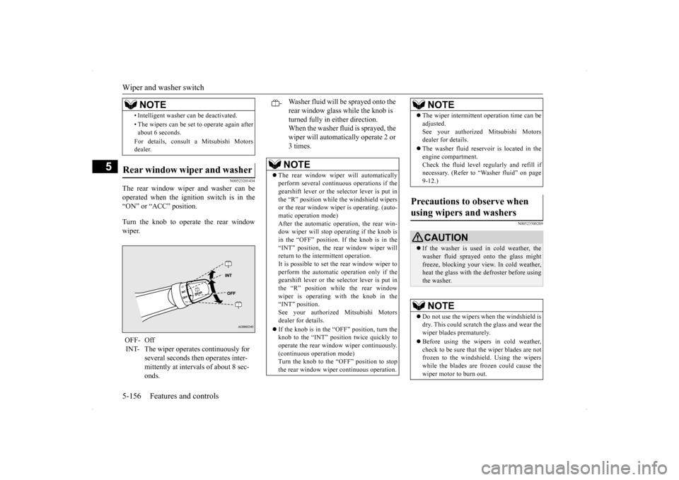
The rear window wiper and washer can be operated when the ignition switch is in the “ON” or “ACC” position. Turn the knob to operate the rear window wiper.
N00523500209
• Intelligent washer can be deactivated. • The wipers can be set to operate again after about 6 seconds. For details, consult a Mitsubishi Motors dealer.
Rear window wiper and washer OFF- Off INT- The wiper operates continuously for
several seconds then operates inter- mittently at intervals of about 8 sec- onds.NOTE
-
Washer fluid will be sprayed onto the rear window glass while the knob is turned fully in either direction. When the washer fluid is sprayed, the wiper will automatically operate 2 or 3 times.NOTE
The rear window wiper will automatically perform several continuous operations if the gearshift lever or the selector lever is put inthe “R” position while the windshield wipers or the rear window wiper is operating. (auto- matic operation mode)After the automatic operation, the rear win- dow wiper will stop operating if the knob is in the “OFF” position. If the knob is in the“INT” position, the rear window wiper will return to the intermittent operation. It is possible to set the rear window wiper toperform the automatic operation only if the gearshift lever or the selector lever is put in the “R” position while the rear windowwiper is operating with the knob in the “INT” position. See your authorized Mitsubishi Motorsdealer for details. If the knob is in the “OFF” position, turn the knob to the “INT” position twice quickly to operate the rear window wiper continuously.(continuous operation mode) Turn the knob to the “OFF” position to stop the rear window wiper continuous operation.
The wiper intermittent operation time can be adjusted. See your authorized Mitsubishi Motors dealer for details. The washer fluid reservoir is located in the engine compartment. Check the fluid level regularly and refill ifnecessary. (Refer to “Washer fluid” on page 9-12.)
Precautions to observe when using wipers and washers
CAUTION If the washer is used in cold weather, the washer fluid sprayed onto the glass might freeze, blocking your view. In cold weather, heat the glass with the defroster before usingthe washer.NOTE
Do not use the wipers when the windshield is dry. This could scratch the glass and wear the wiper blades prematurely. Before using the wipers in cold weather, check to be sure that the wiper blades are not frozen to the windshield. Using the wiperswhile the blades are frozen could cause the wiper motor to burn out.NOTE
BK0200700US.book
156 ページ 2013年2月15日 金曜日 午後12時17分
Page 224 of 422
Electric rear window defogger switch
Features and controls 5-157
5
N00523700315
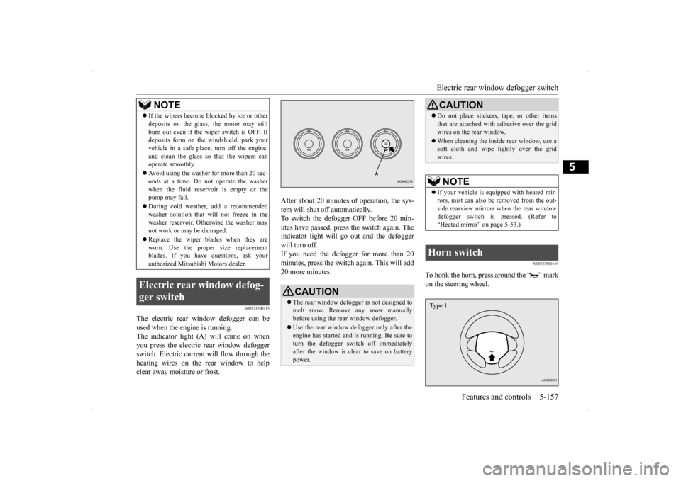
The electric rear window defogger can be used when the engine is running. The indicator light (A) will come on when you press the electric rear window defoggerswitch. Electric current will flow through the heating wires on the rear window to help clear away moisture or frost.
After about 20 minutes of operation, the sys- tem will shut off automatically. To switch the defogger OFF before 20 min-utes have passed, press the switch again. The indicator light will go out and the defogger will turn off. If you need the defogger for more than 20minutes, press the switch
again. This will add
20 more minutes.
N00523800169
To honk the horn, press around the “ ” mark on the steering wheel.
If the wipers become blocked by ice or other deposits on the glass, the motor may still burn out even if the wiper switch is OFF. If deposits form on the windshield, park your vehicle in a safe place, turn off the engine,and clean the glass so that the wipers can operate smoothly. Avoid using the washer for more than 20 sec- onds at a time. Do not operate the washer when the fluid reser
voir is empty or the
pump may fail. During cold weather, add a recommended washer solution that will not freeze in the washer reservoir. Otherwise the washer may not work or may be damaged. Replace the wiper blades when they are worn. Use the proper size replacementblades. If you have questions, ask your authorized Mitsubishi Motors dealer.
Electric rear window defog- ger switch
NOTE
CAUTION The rear window defogger is not designed to melt snow. Remove any snow manuallybefore using the rear window defogger. Use the rear window defogger only after the engine has started and is running. Be sure to turn the defogger switch off immediately after the window is clear to save on batterypower.
Do not place stickers, tape, or other items that are attached with adhesive over the grid wires on the rear window. When cleaning the inside rear window, use a soft cloth and wipe lightly over the grid wires.NOTE
If your vehicle is equipped with heated mir- rors, mist can also be removed from the out-side rearview mirrors when the rear window defogger switch is pressed. (Refer to “Heated mirror” on page 5-53.)
Horn switch
CAUTION
Type 1
BK0200700US.book
157 ページ 2013年2月15日 金曜日 午後12時17分
Page 230 of 422

Bluetooth® 2.0 interface (if so equipped)
Features and controls 5-163
5
If a passcode has been set and the security function is enabled, the voice guide will say“Hands-free system is locked. State the pass- code to continue” when the SPEECH button (except for vehicles with Mitsubishi Multi-Communication System) or PICK-UP button (for vehicles with Mi
tsubishi Multi-Commu-
nication System) is pressed to enter voice rec-ognition mode. Say the 4-digit passcode number to enter the passcode. If the entered passcode is wrong, the voice guide will say “<4-digit passcode>, Incorrectpasscode. Please try again.” Enter the correct passcode.
Use the following procedure to turn off the security function by disabling the passcode. 1. Press the SPEECH button (except for vehicles with Mits
ubishi Multi-Commu-
nication System) or PICK-UP button (forvehicles with Mits
ubishi Multi-Commu-
nication System). 2. Say “Setup.”3. Say “Passcode.” 4. The voice guide will say “Passcode is enabled. Would you like to disable it?”Answer “Yes.” Answer “No” to cancel the disabling of the passcode and return to the main menu.
5. When the disabling of the passcode is completed, the voice guide will say “Pass- code is disabled” and the system will return to the main menu.
N00564700011
The Bluetooth
® 2.0 interface can use the
speaker enrollment function to create a voicemodel for one person per language. This makes it easier for the Bluetooth
® 2.0
interface to recognise voice commands said by you. You can turn a voice model registered with the speaker enrollment function on and off whenever you want.
N00564801093
It takes about 2 to 3 minutes to complete thespeaker enrollment process.To ensure the best results, run through the process while in the driver’s seat, in an envi- ronment that is as quiet as possible (whenthere is no rain or strong winds and the vehi- cle windows are closed). Please turn off your phone while in speaker enrollment to preventinterruption of the process. Use the following procedure for speaker enrollment.
NOTE
Passcode will be required to access the sys- tem after the next ignition cycle. It is required for a little time after engine stop that the entered passcode is actuallyrecorded in the system. If the ignition switch is made to “ACC” or “ON” or the engine is started immediatelyafter engine stop, there is a case when the entered passcode is not recorded in the sys- tem. At this time, please try to enter the pass-code again.
Entering the passcode
NOTE
You can reenter the passcode as many times as you want. If you have forgotten your passcode, say “Cancel” to quit the voice input mode andthen check with an authorized Mitsubishi Motors dealer.
Disabling the passcode
NOTE
System must be unlocked to disable the pass- code.
Speaker enrollment function
Speaker enrollment
BK0200700US.book
163 ページ 2013年2月15日 金曜日 午後12時17分
Page 247 of 422
USB input terminal (if so equipped) 5-180 Features and controls
5
The term “IC:” before the radio certification number only signifies that Industry Canada technical specifications were met. The antenna used for this transmitter must notbe co-located or operating in conjunction with any other antenna or transmitter. End- users and installers must be provided withinstallation instructio
ns and transmitter oper-
ating conditions for satisfying RF exposure compliance.
N00566401093 N00566701054
You can connect your USB memory device or iPod
* to play music files stored in the USB
memory device or iPod.
The following explains how to connect and remove a USB memory device or iPod. Refer to the following sections for details on how to play music files:Refer to “Listen to Audio Files on a USB Device” on page 7-46.
N00566800074
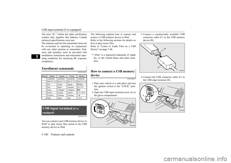
1. Park your vehicle in a safe place and turn the ignition switch to the “LOCK” posi- tion. 2. Open the USB input terminal cover (A) inthe glove compartment.
3. Connect a commercially available USB connector cable (C) to the USB memory device (B). 4. Connect the USB connector cable (C) to the USB input terminal (D).
Enrollment commands
USB input terminal
(if so
equipped)
* :“iPod” is a registered trademark of Apple Inc. in the United States and other coun- tries.
How to connect a USB memory device
BK0200700US.book
180 ページ 2013年2月15日 金曜日 午後12時17分
Page 248 of 422
USB input terminal (if so equipped)
Features and controls 5-181
5
5. To remove the USB connector cable, turn the ignition switch to the “LOCK” posi- tion first and perform the installation steps in reverse.
N00566900059
1. Park your vehicle in a safe place and turnthe ignition switch to the “LOCK” posi- tion.
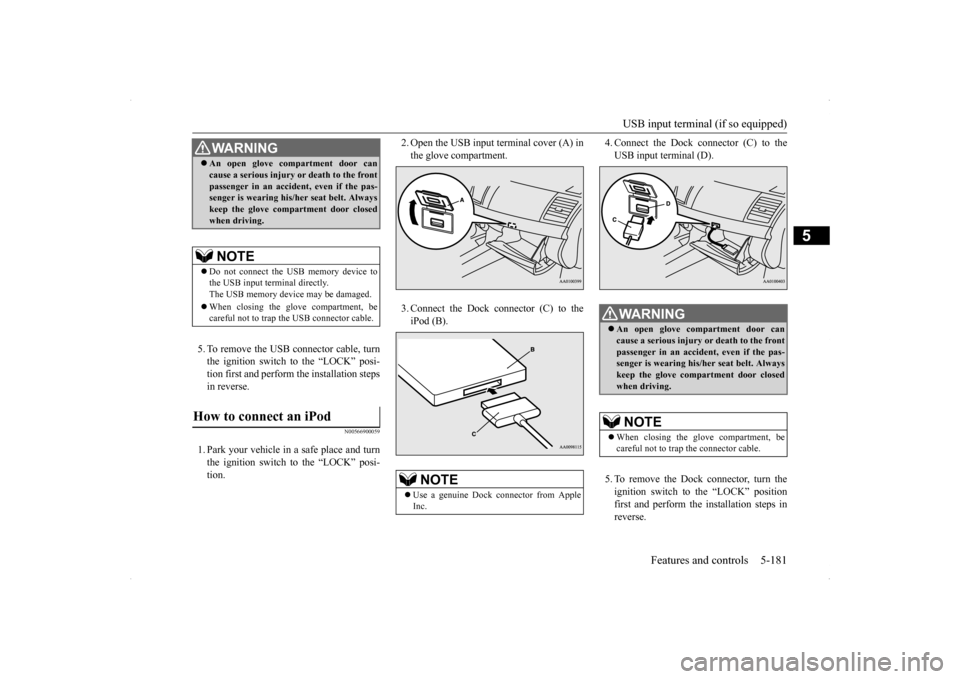
2. Open the USB input terminal cover (A) in the glove compartment. 3. Connect the Dock connector (C) to the iPod (B).
4. Connect the Dock connector (C) to the USB input terminal (D). 5. To remove the Dock connector, turn the ignition switch to the “LOCK” positionfirst and perform the installation steps in reverse.
WA R N I N G An open glove compartment door can cause a serious injury or death to the front passenger in an accident, even if the pas- senger is wearing his/her seat belt. Always keep the glove compartment door closedwhen driving.NOTE
Do not connect the USB memory device to the USB input terminal directly.The USB memory device may be damaged. When closing the glove compartment, be careful not to trap the USB connector cable.
How to connect an iPod
NOTE
Use a genuine Dock connector from Apple Inc.
WA R N I N G An open glove compartment door can cause a serious injury or death to the front passenger in an accident, even if the pas-senger is wearing his/her seat belt. Always keep the glove compartment door closed when driving.NOTE
When closing the glove compartment, be careful not to trap the connector cable.
BK0200700US.book
181 ページ 2013年2月15日 金曜日 午後12時17分