2014 Lancia Voyager light
[x] Cancel search: lightPage 166 of 364

Located in the back of the super con-
sole is a storage drawer and cuphold-
ers for the rear passengers.
CARGO AREA FEATURES
RECHARGEABLE
FLASHLIGHT (for
versions/markets, where
provided)
The rechargeable flashlight is
mounted on the right side of the cargo
area. The flashlight snaps out of the
bezel when needed. The flashlight
features two bright LED light bulbs
and is powered by a lithium battery
that recharges when snapped back
into place and the vehicle is either
running or the key is in the accessory
position.Press in on the flashlight to release it.
To operate the flashlight, press the
switch once for high, twice for low,
and a third time to return to off.
REAR WINDOW
FEATURES
REAR WINDOW
DEFROSTER
The rear window defroster
button is located on the cli-
mate control (Mode) knob. Press this
button to turn on the rear window
defroster and the heated outside mir-
rors (for versions/markets, where
provided). An indicator in the button
will illuminate when the rear window
defroster is on. The rear window de-
froster automatically turns off after
approximately 10 minutes. For an ad-
ditional five minutes of operation,
press the button a second time.
NOTE:
You can turn off the heated mir- ror feature at anytime by press-
ing the rear window defroster
switch a second time.
Rear Drawer Storage
Press And Release
Three-Press Switch
160
Page 169 of 364

CAUTION!
Check deployed crossbars fre-quently and retighten thumb
screws as necessary.
To avoid damage to the roof rack and vehicle, do not exceed the
maximum roof rack load capacity
of 68 kg. Always distribute heavy
loads as evenly as possible and
secure the load appropriately.
To prevent damage to the roof of your vehicle, DO NOT carry any
loads on the roof rack without the
crossbars deployed.
(Continued)
CAUTION!(Continued)
The load should be secured andplaced on top of the crossbars, not
directly on the roof. If it is neces-
sary to place the load on the roof,
place a blanket or other protec-
tive layer between the load and
the roof surface.
Long loads which extend over the windshield, such as wood panels
or surfboards, or loads with large
frontal area should be secured to
both the front and rear of the
vehicle.
Travel at reduced speeds and turn corners carefully when carrying
large or heavy loads on the roof
rack. Wind forces, due to natural
causes or nearby truck traffic,
can add sudden upward lift to a
load. This is especially true on
large flat loads and may result in
damage to the cargo or your ve-
hicle.
WARNING!
Cargo must be securely tied before
driving your vehicle. Improperly
secured loads can fly off the vehicle,
particularly at high speeds, result-
ing in personal injury or property
damage. Follow the roof rack cau-
tions when carrying cargo on your
roof rack.
HEADLIGHT WASHER
(for versions/markets,
where provided)
The multifunction lever operates the
headlight washers when the ignition
switch is in the ON position and the
headlights are turned on. The multi-
function lever is located on the left
side of the steering column.
To use the headlight washers, push
the multifunction lever inward (to-
ward the steering column) to the sec-
ond detent and release it. The head-
light washers will spray a timed high-
pressure spray of washer fluid onto
each headlight lens. In addition, the
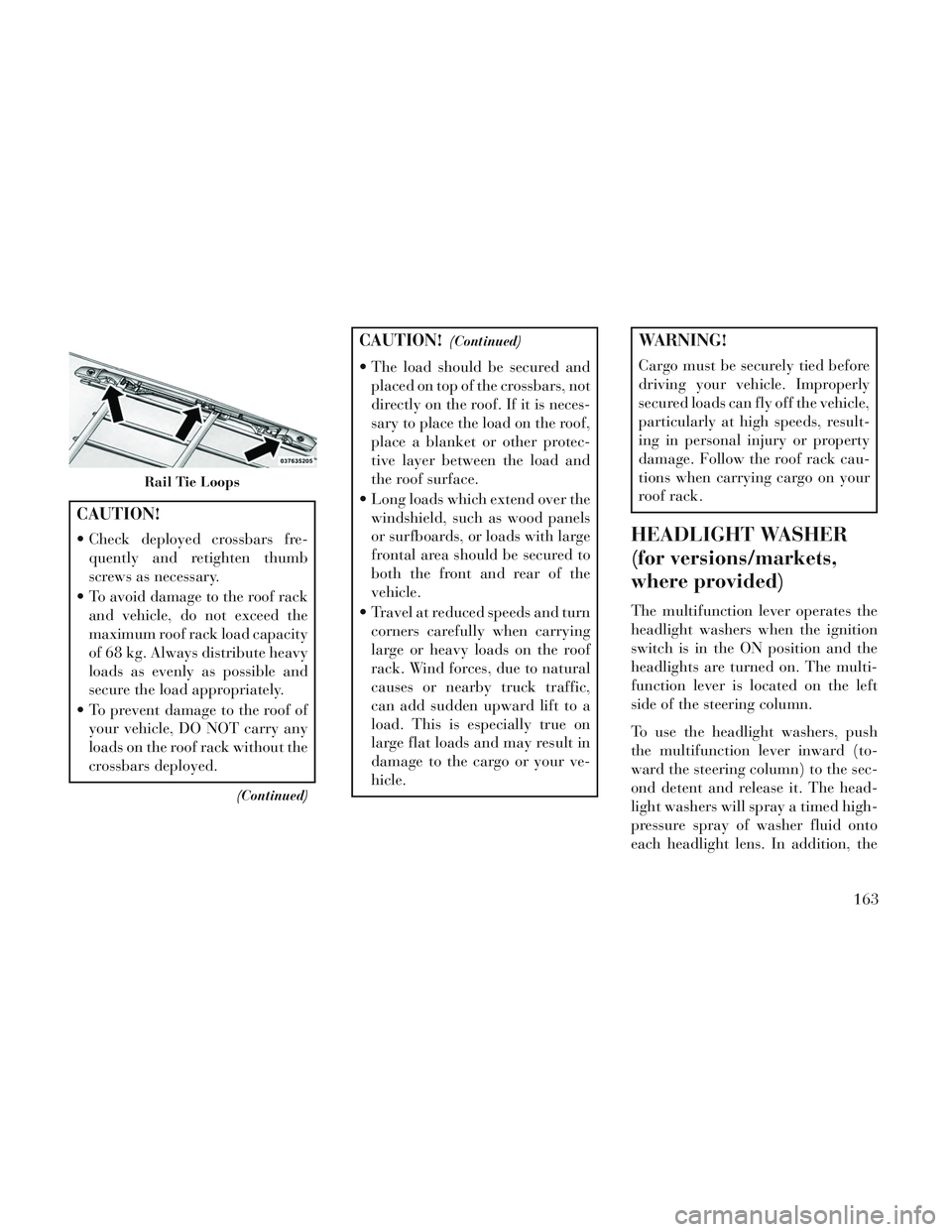
Rail Tie Loops
163
Page 170 of 364

windshield washers will spray the
windshield and the windshield wipers
will cycle.
NOTE: After turning the ignition
switch and headlights ON, the
headlight washers will operate on
the first spray of the windshield
washer and then every eleventh
spray after that.
SUN SCREENS (for
versions/markets, where
provided)
Sun screens are available for second
and third row seating windows. The
screens store in the sill trim panels,
and the tops of the windows are
equipped with hooks that the sun
screens attach to when pulled out.Gently pull up on the tab to raise the
sun screen. Continue pulling the sun
screen until the tab is near the top of
the window.
Once the screen is completely to the
top of the window, extend the top bar
of the sun screen over the two hooks
attached to the top of the window.
To lower the sun screen, gently lift the
tab upward to disengage the hooks,
and feed the screen back into the base
sill.
Sun Screen Retracted
Sun Screen Extended
164
Page 171 of 364

4
UNDERSTANDING YOUR INSTRUMENT
PANEL
INSTRUMENT PANEL FEATURES............169
INSTRUMENT CLUSTER — GASOLINE .......170
INSTRUMENT CLUSTER — DIESEL ..........171
INSTRUMENT CLUSTER DESCRIPTIONS .....172
ELECTRONIC VEHICLE INFORMATION CENTER (EVIC) (for versions/markets, where provided) . .178
ELECTRONIC VEHICLE INFORMATION CENTER (EVIC) DISPLAYS ...................... .179
EVIC WHITE TELLTALE LIGHTS ..........181
EVIC AMBER TELLTALE LIGHTS ..........182
EVIC RED TELLTALE LIGHTS .............182
OIL CHANGE DUE ..................... .184
FUEL ECONOMY ...................... .184
VEHICLE SPEED ...................... .185
TRIP INFO ........................... .185
TIRE BAR ............................ .186
VEHICLE INFO (CUSTOMER INFORMATION FEATURES) .......................... .186
MESSAGES ........................... .186
UNITS .............................. .186
165
Page 175 of 364

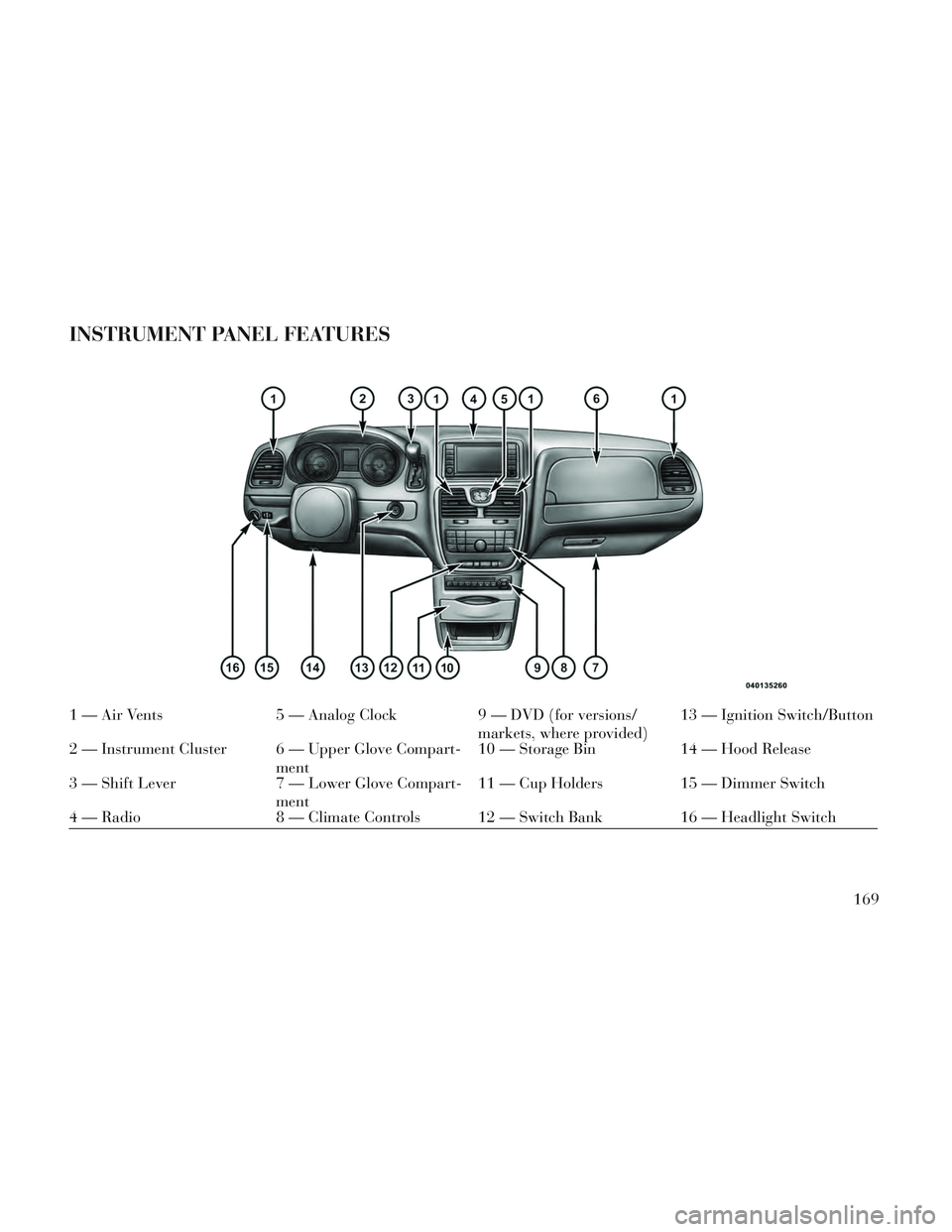
INSTRUMENT PANEL FEATURES
1 — Air Vents5 — Analog Clock9 — DVD (for versions/
markets, where provided)13 — Ignition Switch/Button
2 — Instrument Cluster 6 — Upper Glove Compart- ment10 — Storage Bin
14 — Hood Release
3 — Shift Lever 7 — Lower Glove Compart-
ment11 — Cup Holders 15 — Dimmer Switch
4 — Radio 8 — Climate Controls 12 — Switch Bank 16 — Headlight Switch
169
Page 178 of 364

INSTRUMENT CLUSTER
DESCRIPTIONS
1. Tachometer
The red segments indicate the maxi-
mum permissible engine revolutions
per minute (RPM x 1000) for each
gear range. Before reaching the red
area, ease up on the accelerator.
2. Front Fog Light Indicator (for
versions/markets, where provided)This indicator will illumi-
nate when the front fog
lights are on.
3. Park/Headlight ON Indicator
This indicator will illumi-
nate when the park lights or
headlights are turned on.
4. Turn Signal Indicators The arrow will flash with
the exterior turn signal
when the turn signal lever is
operated.
If the vehicle is driven 1.6 km with
either turn signal on, a continuous
chime will sound to alert you to turn the signal off. If either indicator
flashes at a rapid rate, check for a
defective outside light bulb.
5. High Beam Indicator
This indicator shows that the
high beam headlights are on.
Push the multifunction lever forward
to switch the headlights to high beam,
and pull toward yourself (normal po-
sition) to return to low beam.
6. Odometer Display / Electronic
Vehicle Information Center (EVIC)
Display
Odometer Display / Trip Odometer
Display (for versions/markets,
where provided) The odometer dis-
play shows the total distance the ve-
hicle has been driven.
NOTE: Some warnings will be
displayed in the Electronic Vehicle
Information Center Display Area
located in the instrument cluster.
Refer to ”Electronic Vehicle Infor-
mation Center (EVIC) Display”
(for versions/markets, where pro-
vided) for further information. LoW tirE
When the appropriate condition ex-
ists, the odometer display will toggle
between LoW and tirE for three
cycles.
gASCAP
If the vehicle diagnostic system deter-
mines that the fuel filler cap is loose,
improperly installed, or damaged, a
“gASCAP” message will display in the
odometer display area. Tighten the
fuel filler cap properly and press the
STEP button on the steering wheel to
turn off the message. If the problem
continues, the message will appear
the next time the vehicle is started.
noFUSE
If the vehicle diagnostic system deter-
mines that the Ignition Off Draw
(IOD) fuse is improperly installed, or
damaged, a “noFUSE” message will
display in the odometer display area.
For further information on fuses and
fuse locations refer to “Fuses” in
“Maintaining Your Vehicle”.
172
Page 179 of 364

CHAngE OIL
Your vehicle is equipped with an en-
gine oil change indicator system. The
CHAngE OILmessage will flash in
the instrument cluster odometer for
approximately 12 seconds, after a
single chime has sounded, to indicate
the next scheduled oil change inter-
val. The engine oil change indicator
system is duty cycle-based, which
means the engine oil change interval
may fluctuate dependent upon your
personal driving style.
Unless reset, this message will con-
tinue to display each time you turn the
ignition switch to the ON/RUN posi-
tion. To turn off the message tempo-
rarily, press and release the STEP
button on the steering wheel. To reset
the oil change indicator system (after
performing the scheduled mainte-
nance), perform the following steps.
1. Turn the ignition switch to the ON/
RUN position (do not start the en-
gine).
2. Fully depress the accelerator pedal,
slowly, three times within 10 seconds. 3. Turn the ignition switch to the
OFF/LOCK position.
NOTE: If the indicator message
illuminates when you start the en-
gine, the oil change indicator sys-
tem did not reset. If necessary, re-
peat these steps.
Electronic Vehicle Information
Center (EVIC) Display (for versions/
markets, where provided)
The Electronic Vehicle Information
Center (EVIC) features a driver-
interactive display that is located in
the instrument cluster. For further in-
formation, refer to “Electronic Ve-
hicle Information Center (EVIC)”.
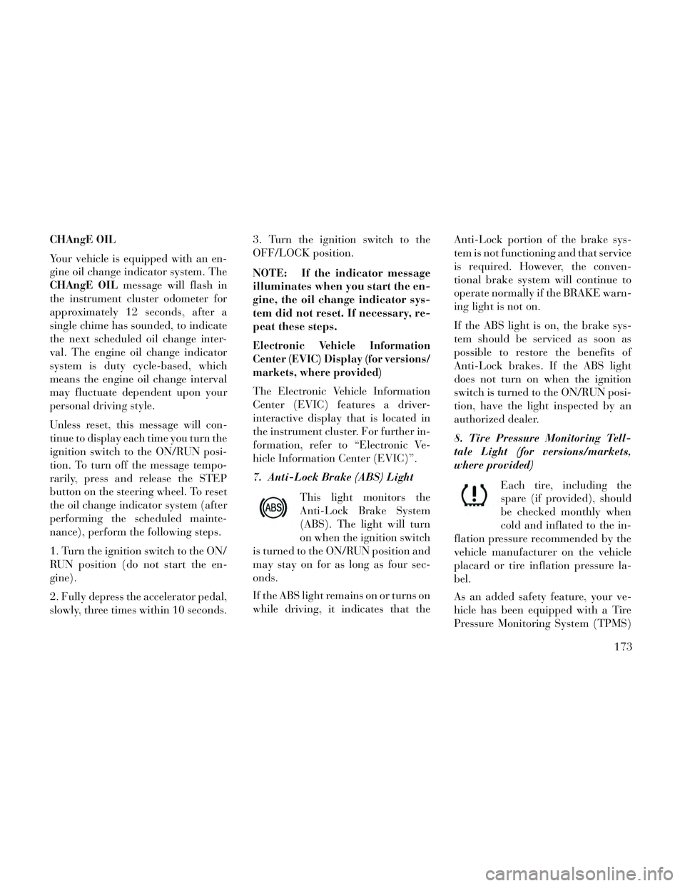
7. Anti-Lock Brake (ABS) Light
This light monitors the
Anti-Lock Brake System
(ABS). The light will turn
on when the ignition switch
is turned to the ON/RUN position and
may stay on for as long as four sec-
onds.
If the ABS light remains on or turns on
while driving, it indicates that the Anti-Lock portion of the brake sys-
tem is not functioning and that service
is required. However, the conven-
tional brake system will continue to
operate normally if the BRAKE warn-
ing light is not on.
If the ABS light is on, the brake sys-
tem should be serviced as soon as
possible to restore the benefits of
Anti-Lock brakes. If the ABS light
does not turn on when the ignition
switch is turned to the ON/RUN posi-
tion, have the light inspected by an
authorized dealer.
8. Tire Pressure Monitoring Tell-
tale Light (for versions/markets,
where provided)
Each tire, including the
spare (if provided), should
be checked monthly when
cold and inflated to the in-
flation pressure recommended by the
vehicle manufacturer on the vehicle
placard or tire inflation pressure la-
bel.
As an added safety feature, your ve-
hicle has been equipped with a Tire
Pressure Monitoring System (TPMS)
173
Page 180 of 364

that illuminates a low tire pressure
telltale when one or more of your tires
is significantly under-inflated. Ac-
cordingly, when the low tire pressure
telltale illuminates, you should stop
and check your tires as soon as pos-
sible, and inflate them to the proper
pressure. Driving on a significantly
under-inflated tire causes the tire to
overheat and can lead to tire failure.
Under-inflation also reduces fuel effi-
ciency and tire tread life, and may
affect the vehicle’s handling and stop-
ping ability.
Please note that the TPMS is not a
substitute for proper tire mainte-
nance, and it is the driver’s responsi-
bility to maintain correct tire pres-
sure, even if under-inflation has not
reached the level to trigger illumina-
tion of the TPMS low tire pressure
telltale.
Your vehicle has also been equipped
with a TPMS malfunction indicator to
indicate when the system is not oper-
ating properly. The TPMS malfunc-
tion indicator is combined with the
low tire pressure telltale. When thesystem detects a malfunction, the tell-
tale will flash for approximately one
minute and then remain continuously
illuminated. This sequence will con-
tinue upon subsequent vehicle start-
ups as long as the malfunction exists.
When the malfunction indicator is il-
luminated, the system may not be
able to detect or signal low tire pres-
sure as intended. TPMS malfunctions
may occur for a variety of reasons,
including the installation of replace-
ment or alternate tires or wheels on
the vehicle that prevent the TPMS
from functioning properly. Always
check the TPMS malfunction telltale
after replacing one or more tires or
wheels on your vehicle, to ensure that
the replacement or alternate tires and
wheels allow the TPMS to continue to
function properly.CAUTION!
The TPMS has been optimized for
the original equipment tires and
wheels. TPMS pressures and warn-
ing have been established for the
tire size equipped on your vehicle.
Undesirable system operation or
sensor damage may result when us-
ing replacement equipment that is
not of the same size, type, and/or
style. Aftermarket wheels can cause
sensor damage. Do not use tire seal-
ant from a can or balance beads if
your vehicle is equipped with a
TPMS, as damage to the sensors
may result.
9. Malfunction Indicator Light
(MIL) The Malfunction Indicator
Light (MIL) is part of an on-
board diagnostic system,
called OBD, that monitors engine and
automatic transmission control sys-
tems. The light will illuminate when
the key is in the ON/RUN position,
before engine start. If the bulb does
174