2014 Lancia Voyager ignition
[x] Cancel search: ignitionPage 144 of 364

speed. Each subsequent tap of the
button results in a decrease of
1.6 km/h.
TO ACCELERATE FOR
PASSING
Press the accelerator as you would
normally. When the pedal is released,
the vehicle will return to the set speed.
Using Electronic Speed Control
On Hills
The transmission may downshift on
hills to maintain the vehicle set speed.
NOTE: The Electronic Speed
Control system maintains speed up
and down hills. A slight speed
change on moderate hills is nor-
mal.
On steep hills, a greater speed loss or
gain may occur so it may be prefer-
able to drive without Electronic Speed
Control.
WARNING!
Electronic Speed Control can be
dangerous where the system cannot
maintain a constant speed. Your ve-
hicle could go too fast for the con-
ditions, and you could lose control
and have an accident. Do not use
Electronic Speed Control in heavy
traffic or on roads that are winding,
icy, snow-covered or slippery.
PARKSENSE® REAR
PARK ASSIST (for
versions/markets, where
provided)
The ParkSense® Rear Park Assist sys-
tem provides visual and audible indi-
cations of the distance between the rear
fascia and a detected obstacle when
backing up, e.g. during a parking ma-
neuver. Refer to ParkSense® System
Usage Precautions for limitations of
this system and recommendations.
ParkSense® will retain the last system
state (enabled or disabled) from the
last ignition cycle when the ignition is
changed to the ON/RUN position.
ParkSense® can be active only when
the shift lever is in REVERSE. If
ParkSense® is enabled at this shift
lever position, the system will remain
active until the vehicle speed is in-
creased to approximately 11 km/h or
above. The system will become active
again if the vehicle speed is decreased
to speeds less than approximately
9 km/h.
PARK ASSIST SENSORS
The four Park Assist sensors, located
in the rear fascia/bumper, monitor the
area behind the vehicle that is within
the sensors’ field of view. The sensors
can detect obstacles from approxi-
mately 30 cm up to 200 cm from the
rear fascia/bumper in the horizontal
direction, depending on the location,
type and orientation of the obstacle.
PARKSENSE® WARNING
DISPLAY
The ParkSense® Warning screen will
only be displayed if Sound and Dis-
play is selected from the Customer-
Programmable Features section of the
Electronic Vehicle Information Center
138
Page 147 of 364

instrument cluster will actuate a
single chime, once per ignition cycle,
and it will display the “PARKSENSE
UNAVAILABLE WIPE REAR SEN-
SORS” or the “PARKSENSE UN-
AVAILABLE SERVICE REQUIRED”
message. Refer to “Electronic Vehicle
Information Center (EVIC)” in “Un-
derstanding Your Instrument Panel”
for further information. When the
shift lever is moved to REVERSE and
the system has detected a faulted con-
dition, the EVIC will display the
"PARKSENSE UNAVAILABLE
WIPE REAR SENSORS" or
"PARKSENSE UNAVAILABLE SER-
VICE REQUIRED" message for as
long as the vehicle is in REVERSE.
Under this condition, ParkSense will
not operate.
If “PARKSENSE UNAVAILABLE
WIPE REAR SENSORS” appears in
the Electronic Vehicle Information
Center (EVIC) make sure the outer
surface and the underside of the rear
fascia/bumper is clean and clear ofsnow, ice, mud, dirt or other obstruc-
tion and then cycle the ignition. If the
message continues to appear, see an
authorized dealer.
If “PARKSENSE UNAVAILABLE
SERVICE REQUIRED” appears in
the EVIC, see an authorized dealer.
CLEANING THE PARK
ASSIST SYSTEM
Clean the sensors with water, car
wash soap and a soft cloth. Do not use
rough or hard cloths. Do not scratch
or poke the sensors. Otherwise, you
could damage the sensors.
PARKSENSE® SYSTEM
USAGE PRECAUTIONS
NOTE:
Ensure that the rear bumper is
free of snow, ice, mud, dirt and
debris to keep the ParkSense®
system operating properly.
Jackhammers, large trucks, and other vibrations could affect the
performance of ParkSense®. When you turn ParkSense® off,
the instrument cluster will dis-
play “PARK ASSIST SYSTEM
OFF.” Furthermore, once you
turn ParkSense® off, it remains
off until you turn it on again,
even if you cycle the ignition key.
When you move the shift lever to the REVERSE position and
ParkSense® is turned off, the
EVIC will display “PARK AS-
SIST SYSTEM OFF” message for
as long as the vehicle is in
REVERSE.
ParkSense®, when on, will re- duce the radio volume when it is
sounding a tone.
Clean the ParkSense® sensors regularly, taking care not to
scratch or damage them. The
sensors must not be covered
with ice, snow, slush, mud, dirt
or debris. Failure to do so can
result in the system not working
properly. The ParkSense® sys-
tem might not detect an obstacle
behind the fascia/bumper, or it
141
Page 154 of 364

CLOSING SUNROOF —
EXPRESS
Press the switch forward and release it
within one-half second, and the sun-
roof will close automatically from any
position. The sunroof will close fully
and then stop automatically. This is
called “Express Close”. During Ex-
press Close operation, any movement
of the sunroof switch will stop the
sunroof.
CLOSING SUNROOF —
MANUAL MODE
To close the sunroof, press and hold
the switch in the forward position.
Any release of the switch will stop the
movement and the sunroof will re-
main in a partially closed condition
until the switch is pushed and held
forward again.
PINCH PROTECT FEATURE
This feature will detect an obstruction
in the opening of the sunroof during
Express Close operation. If an ob-
struction in the path of the sunroof isdetected, the sunroof will automati-
cally retract. Remove the obstruction
if this occurs. Next, press the switch
forward and release to Express Close.
NOTE: If three consecutive sun-
roof close attempts result in Pinch
Protect reversals, the fourth close
attempt will be a Manual Close
movement with Pinch Protect dis-
abled.
VENTING SUNROOF —
EXPRESS
Press and release the “Vent” button,
and the sunroof will open to the vent
position. This is called “Express
Vent”, and will occur regardless of
sunroof position. During Express Vent
operation, any movement of the
switch will stop the sunroof.
SUNSHADE OPERATION
The sunshade can be opened manu-
ally. However, the sunshade will open
automatically as the sunroof opens.
NOTE: The sunshade cannot be
closed if the sunroof is open.
WIND BUFFETING
Wind buffeting can be described as
the perception of pressure on the ears
or a helicopter-type sound in the ears.
Your vehicle may exhibit wind buffet-
ing with the windows down, or the
sunroof (for versionis/markets, where
provided) is in certain open or par-
tially open positions. This is a normal
occurrence and can be minimized. If
the buffeting occurs with the rear
windows open, open the front and
rear windows together to minimize
the buffeting. If the buffeting occurs
with the sunroof open, adjust the sun-
roof opening to minimize the buffet-
ing or open any window.
SUNROOF MAINTENANCE
Use only a non-abrasive cleaner and a
soft cloth to clean the glass panel.
IGNITION OFF OPERATION
For vehicles not equipped with the
Electronic Vehicle Information
Center (EVIC)
The power sunroof switch will remain
active for 45 seconds after the ignition
148
Page 155 of 364

switch is turned to the LOCK posi-
tion. Opening either front door will
cancel this feature.
For Vehicles Equipped With The
EVIC
The power sunroof switch will remain
active for up to approximately ten
minutes after the ignition switch is
turned to the LOCK position. Open-
ing either front door will cancel this
feature.
ELECTRICAL POWER
OUTLETS
Two 12 Volt (13 Amp) power outlets
are located on the lower instrument
panel, below the open storage bin.
The driver-side power outlet is con-
trolled by the ignition switch and the
passenger-side power outlet is con-
nected directly to the battery. The
driver-side power outlet will also op-
erate a conventional cigar lighter unit
(for versions/markets, where pro-
vided with an optional Smoker's
Package).
CAUTION!
Do not exceed the maximumpower of 160 Watts (13 Amps) at
12 Volts. If the 160 Watt (13
Amp) power rating is exceeded
the fuse protecting the system will
need to be replaced.
Power outlets are designed for ac- cessory plugs only. Do not insert
any other object in the power out-
lets as this will damage the outlet
and blow the fuse. Improper use
of the power outlet can cause
damage not covered by your New
Vehicle Limited Warranty.
One outlet in the removable floor con-
sole (for versions/markets, where pro-
vided) shares a fuse with the lower
outlet in the instrument panel and is also connected to the battery. Do not
exceed a maximum power of 160
Watts (13 Amps) shared between the
lower panel outlet and the removable
floor console outlet.
On vehicles equipped with the Super
Console the power outlets are located
under the retractable cover. To access
the power outlets push down on the
cover and slide it toward the instru-
ment panel.
Instrument Panel Outlets
Super Console Outlets
Super Console Outlets
149
Page 169 of 364

CAUTION!
Check deployed crossbars fre-quently and retighten thumb
screws as necessary.
To avoid damage to the roof rack and vehicle, do not exceed the
maximum roof rack load capacity
of 68 kg. Always distribute heavy
loads as evenly as possible and
secure the load appropriately.
To prevent damage to the roof of your vehicle, DO NOT carry any
loads on the roof rack without the
crossbars deployed.
(Continued)
CAUTION!(Continued)
The load should be secured andplaced on top of the crossbars, not
directly on the roof. If it is neces-
sary to place the load on the roof,
place a blanket or other protec-
tive layer between the load and
the roof surface.
Long loads which extend over the windshield, such as wood panels
or surfboards, or loads with large
frontal area should be secured to
both the front and rear of the
vehicle.
Travel at reduced speeds and turn corners carefully when carrying
large or heavy loads on the roof
rack. Wind forces, due to natural
causes or nearby truck traffic,
can add sudden upward lift to a
load. This is especially true on
large flat loads and may result in
damage to the cargo or your ve-
hicle.
WARNING!
Cargo must be securely tied before
driving your vehicle. Improperly
secured loads can fly off the vehicle,
particularly at high speeds, result-
ing in personal injury or property
damage. Follow the roof rack cau-
tions when carrying cargo on your
roof rack.
HEADLIGHT WASHER
(for versions/markets,
where provided)
The multifunction lever operates the
headlight washers when the ignition
switch is in the ON position and the
headlights are turned on. The multi-
function lever is located on the left
side of the steering column.
To use the headlight washers, push
the multifunction lever inward (to-
ward the steering column) to the sec-
ond detent and release it. The head-
light washers will spray a timed high-
pressure spray of washer fluid onto
each headlight lens. In addition, the
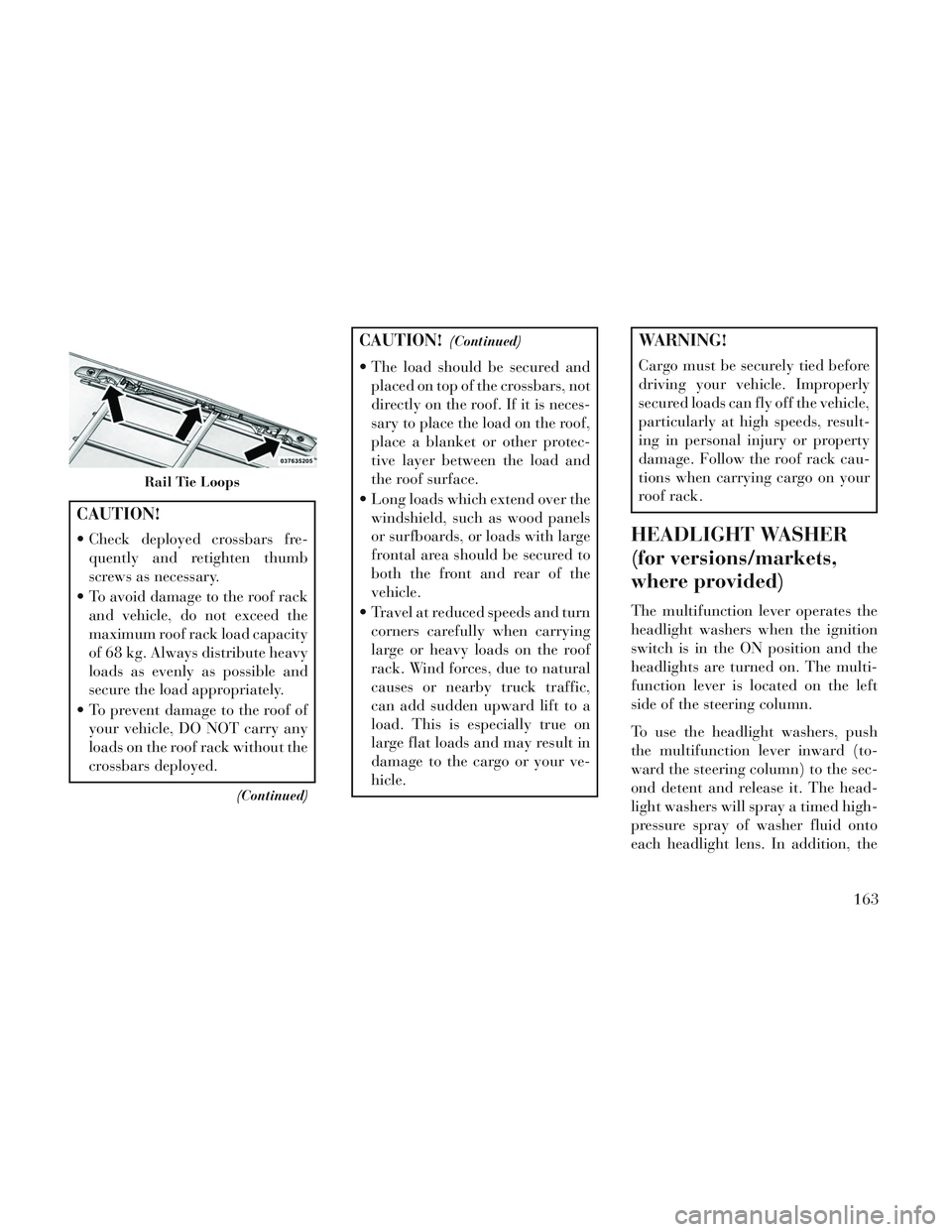
Rail Tie Loops
163
Page 170 of 364

windshield washers will spray the
windshield and the windshield wipers
will cycle.
NOTE: After turning the ignition
switch and headlights ON, the
headlight washers will operate on
the first spray of the windshield
washer and then every eleventh
spray after that.
SUN SCREENS (for
versions/markets, where
provided)
Sun screens are available for second
and third row seating windows. The
screens store in the sill trim panels,
and the tops of the windows are
equipped with hooks that the sun
screens attach to when pulled out.Gently pull up on the tab to raise the
sun screen. Continue pulling the sun
screen until the tab is near the top of
the window.
Once the screen is completely to the
top of the window, extend the top bar
of the sun screen over the two hooks
attached to the top of the window.
To lower the sun screen, gently lift the
tab upward to disengage the hooks,
and feed the screen back into the base
sill.
Sun Screen Retracted
Sun Screen Extended
164
Page 175 of 364

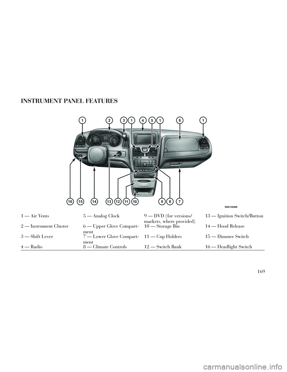
INSTRUMENT PANEL FEATURES
1 — Air Vents5 — Analog Clock9 — DVD (for versions/
markets, where provided)13 — Ignition Switch/Button
2 — Instrument Cluster 6 — Upper Glove Compart- ment10 — Storage Bin
14 — Hood Release
3 — Shift Lever 7 — Lower Glove Compart-
ment11 — Cup Holders 15 — Dimmer Switch
4 — Radio 8 — Climate Controls 12 — Switch Bank 16 — Headlight Switch
169
Page 178 of 364

INSTRUMENT CLUSTER
DESCRIPTIONS
1. Tachometer
The red segments indicate the maxi-
mum permissible engine revolutions
per minute (RPM x 1000) for each
gear range. Before reaching the red
area, ease up on the accelerator.
2. Front Fog Light Indicator (for
versions/markets, where provided)This indicator will illumi-
nate when the front fog
lights are on.
3. Park/Headlight ON Indicator
This indicator will illumi-
nate when the park lights or
headlights are turned on.
4. Turn Signal Indicators The arrow will flash with
the exterior turn signal
when the turn signal lever is
operated.
If the vehicle is driven 1.6 km with
either turn signal on, a continuous
chime will sound to alert you to turn the signal off. If either indicator
flashes at a rapid rate, check for a
defective outside light bulb.
5. High Beam Indicator
This indicator shows that the
high beam headlights are on.
Push the multifunction lever forward
to switch the headlights to high beam,
and pull toward yourself (normal po-
sition) to return to low beam.
6. Odometer Display / Electronic
Vehicle Information Center (EVIC)
Display
Odometer Display / Trip Odometer
Display (for versions/markets,
where provided) The odometer dis-
play shows the total distance the ve-
hicle has been driven.
NOTE: Some warnings will be
displayed in the Electronic Vehicle
Information Center Display Area
located in the instrument cluster.
Refer to ”Electronic Vehicle Infor-
mation Center (EVIC) Display”
(for versions/markets, where pro-
vided) for further information. LoW tirE
When the appropriate condition ex-
ists, the odometer display will toggle
between LoW and tirE for three
cycles.
gASCAP
If the vehicle diagnostic system deter-
mines that the fuel filler cap is loose,
improperly installed, or damaged, a
“gASCAP” message will display in the
odometer display area. Tighten the
fuel filler cap properly and press the
STEP button on the steering wheel to
turn off the message. If the problem
continues, the message will appear
the next time the vehicle is started.
noFUSE
If the vehicle diagnostic system deter-
mines that the Ignition Off Draw
(IOD) fuse is improperly installed, or
damaged, a “noFUSE” message will
display in the odometer display area.
For further information on fuses and
fuse locations refer to “Fuses” in
“Maintaining Your Vehicle”.
172