2014 Lancia Voyager warning light
[x] Cancel search: warning lightPage 119 of 364

POWER LUMBAR (for
versions/markets, where
provided)
Vehicles equipped with power driver
or passenger seats may be also be
equipped with power lumbar. The
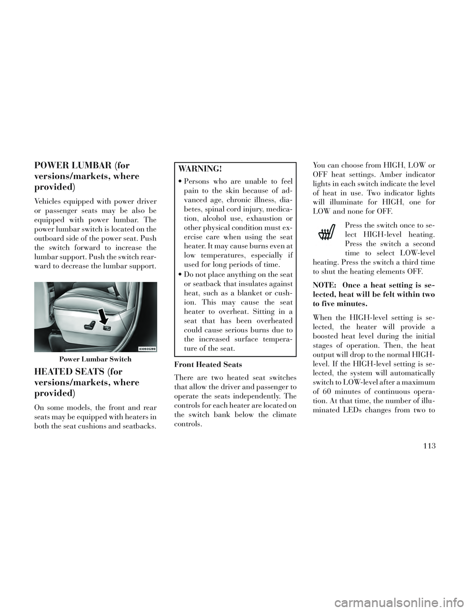
power lumbar switch is located on the
outboard side of the power seat. Push
the switch forward to increase the
lumbar support. Push the switch rear-
ward to decrease the lumbar support.
HEATED SEATS (for
versions/markets, where
provided)
On some models, the front and rear
seats may be equipped with heaters in
both the seat cushions and seatbacks.
WARNING!
Persons who are unable to feelpain to the skin because of ad-
vanced age, chronic illness, dia-
betes, spinal cord injury, medica-
tion, alcohol use, exhaustion or
other physical condition must ex-
ercise care when using the seat
heater. It may cause burns even at
low temperatures, especially if
used for long periods of time.
Do not place anything on the seat or seatback that insulates against
heat, such as a blanket or cush-
ion. This may cause the seat
heater to overheat. Sitting in a
seat that has been overheated
could cause serious burns due to
the increased surface tempera-
ture of the seat.
Front Heated Seats
There are two heated seat switches
that allow the driver and passenger to
operate the seats independently. The
controls for each heater are located on
the switch bank below the climate
controls. You can choose from HIGH, LOW or
OFF heat settings. Amber indicator
lights in each switch indicate the level
of heat in use. Two indicator lights
will illuminate for HIGH, one for
LOW and none for OFF.
Press the switch once to se-
lect HIGH-level heating.
Press the switch a second
time to select LOW-level
heating. Press the switch a third time
to shut the heating elements OFF.
NOTE: Once a heat setting is se-
lected, heat will be felt within two
to five minutes.
When the HIGH-level setting is se-
lected, the heater will provide a
boosted heat level during the initial
stages of operation. Then, the heat
output will drop to the normal HIGH-
level. If the HIGH-level setting is se-
lected, the system will automatically
switch to LOW-level after a maximum
of 60 minutes of continuous opera-
tion. At that time, the number of illu-
minated LEDs changes from two to
Power Lumbar Switch
113
Page 121 of 364

WARNING!
Adjusting a seat while drivingmay be dangerous. Moving a seat
while driving could result in loss
of control which could cause a
collision and serious injury or
death.
Seats should be adjusted before fastening the seat belts and while
the vehicle is parked. Serious in-
jury or death could result from a
poorly adjusted seat belt.
MANUAL RECLINING
SEATS
For models equipped with manual re-
clining seats, the recline lever is lo-
cated on the outboard side of the seat. To recline, lean forward slightly, lift
the lever, then push back to the de-
sired position and release the lever.
Lean forward and lift the lever to
return the seatback to its normal po-
sition. Using body pressure, lean for-
ward and rearward on the seat to be
sure the seatback has latched.
WARNING!
Do not ride with the seatback re-
clined so that the shoulder belt is no
longer resting against your chest. In
a collision you could slide under the
seat belt, which could result in seri-
ous injury or death.
HEAD RESTRAINTS
Head restraints are designed to reduce
the risk of injury by restricting head
movement in the event of a rear im-
pact. Head restraints should be ad-
justed so that the top of the head
restraint is located above the top of
your ear.
WARNING!
The head restraints for all occu-
pants must be properly adjusted
prior to operating the vehicle or
occupying a seat. Head restraints
should never be adjusted while the
vehicle is in motion. Driving a ve-
hicle with the head restraints im-
properly adjusted or removed could
cause serious injury or death in the
event of a collision.
Active Head Restraints — Front
Seats
Active Head Restraints are passive,
deployable components, and vehicles
with this equipment cannot be readily
identified by any markings, only
through visual inspection of the head
restraint. The head restraint will be
split in two halves, with the front half
being soft foam and trim, the back
half being decorative plastic.
When AHRs deploy during a rear im-
pact, the front half of the head re-
straint extends forward to minimize
the gap between the back of the occu-
pant’s head and the AHR. This system
Manual Recline Lever
115
Page 126 of 364

Easy Entry Second Row
The second row Stow 'n Go® seats
allow easy entry to the third row seat
or rear cargo area.
Pull up on the seatback recliner lever
on the outboard side of the seat.
The seat will automatically fold into
position for easy entry into the third
row.
WARNING!
In the event of a collision you could
be injured if the seat is not fully
latched.
QUAD SEATS (for
versions/markets, where
provided)
Both Quad seats are adjustable for-
ward or rearward. The manual seat
adjustment handle is located under
the seat cushion at the front edge of
each seat.
While sitting in the seat, pull up on
the handle and slide the seat forward
or rearward. Release the bar once you
have reached the desired position.
Then, using body pressure, move for-
ward and rearward on the seat to be
sure that the seat adjusters have
latched.
WARNING!
Adjusting a seat while drivingmay be dangerous. Moving a seat
while driving could result in loss
of control which could cause a
collision and serious injury or
death.
Seats should be adjusted before fastening the seat belts and while
the vehicle is parked. Serious in-
jury or death could result from a
poorly adjusted seat belt.
Manual Recline
To recline, lean forward slightly, lift
the lever, then push back to the de-
sired position and release the lever.
Lean forward and lift the lever to
return the seatback to its normal po-
sition. Using body pressure, lean for-
ward and rearward on the seat to be
sure the seatback has latched.
Seatback Recliner Lever, Seat
Tumble, And Head Restraint Fold Lever
Manual Seat Adjuster
120
Page 134 of 364

you. For details, refer to “Elec-
tronic Vehicle Information Center
(EVIC)/Customer-Programmable
Features” in “Understanding Your
Instrument Panel” for further in-
formation.
TO OPEN AND CLOSE
THE HOOD
To open the hood, two latches must be
released.
1. Pull the hood release lever located
on the instrument panel, below the
steering column.
2. Move to the front of the vehicle
and look inside the center of the hood
opening. Locate, then push the safety
catch lever downward while raising
the hood at the same time.Use the hood prop rod to secure the
hood in the open position.
CAUTION!
To prevent possible damage, do not
slam the hood to close it. Lower the
hood until it is open approximately
30 cm and then drop it. This should
secure both latches. Never drive
your vehicle unless the hood is fully
closed, with both latches engaged.
WARNING!
Be sure the hood is fully latched
before driving your vehicle. If the
hood is not fully latched, it could
open when the vehicle is in motion
and block your vision. Failure to
follow this warning could result in
serious injury or death.
LIGHTS
All of the lights, except the Hazard
Warning lights, headlight high beams
and flash-to-pass, are controlled by
switches to the left of the steering
column on the instrument panel.
Hood Release Lever
Safety Lever Location
Headlight Switch With Halo Control
Assembly
128
Page 137 of 364

come on. Press the switch a second
time and the rear fog lights will come
on (front fog lights stay on). Press the
switch a third time and the rear fog
lights turn off (front fog stays on).
Press the switch a fourth times and
the front fog turns off. For vehicles
without front fog, rear fog will acti-
vate on the first press.
An indicator light in the instrument
cluster illuminates when the fog lights
are turned on.
NOTE: The headlight switch must
be in parking lights or headlights
position to activate the front and
rear fog lamps.
BATTERY PROTECTION
This feature provides battery protec-
tion to avoid wearing down the bat-
tery if the headlights, parking lights,
or front fog lights are left on for ex-
tended periods of time when the igni-
tion switch is in the LOCK position.
After eight minutes of the ignition
switch being in the LOCK position
and the headlight switch in any posi-
tion other than OFF or AUTO, thelights will turn off automatically until
the next cycle of the ignition switch or
headlight switch.
The battery protection feature will be
disabled if the ignition switch is
turned to any other position other
than LOCK during the eight minute
delay.
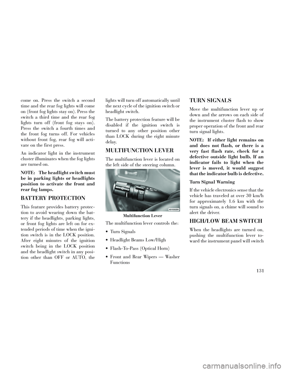
MULTIFUNCTION LEVER
The multifunction lever is located on
the left side of the steering column.
The multifunction lever controls the:
Turn Signals
Headlight Beams Low/High
Flash-To-Pass (Optical Horn)
Front and Rear Wipers — Washer
Functions
TURN SIGNALS
Move the multifunction lever up or
down and the arrows on each side of
the instrument cluster flash to show
proper operation of the front and rear
turn signal lights.
NOTE: If either light remains on
and does not flash, or there is a
very fast flash rate, check for a
defective outside light bulb. If an
indicator fails to light when the
lever is moved, it would suggest
that the indicator bulb is defective.
Turn Signal Warning
If the vehicle electronics sense that the
vehicle has traveled at over 30 km/h
for approximately 1.6 km with the
turn signals on, a chime will sound to
alert the driver.
HIGH/LOW BEAM SWITCH
When the headlights are turned on,
pushing the multifunction lever to-
ward the instrument panel will switch
Multifunction Lever
131
Page 143 of 364

to shut down if multiple Speed
Control functions are operated at
the same time. If this occurs, the
Electronic Speed Control System
can be reactivated by pushing the
Electronic Speed Control ON/OFF
button and resetting the desired
vehicle set speed.
TO ACTIVATE
Push the ON/OFF button. The Cruise
Indicator Light in the instrument
cluster will illuminate. To turn the
system off, push the ON/OFF button
a second time. The Cruise Indicator
Light will turn off. The system should
be turned off when not in use.
WARNING!
Leaving the Electronic Speed Con-
trol system on when not in use is
dangerous. You could accidentally
set the system or cause it to go
faster than you want. You could
lose control and have an accident.
Always leave the system OFF when
you are not using it.
TO SET A DESIRED SPEED
Turn the Electronic Speed Control
ON. When the vehicle has reached the
desired speed, press the SET (-) but-
ton and release. Release the accelera-
tor and the vehicle will operate at the
selected speed.
NOTE: The vehicle should be
traveling at a steady speed and on
level ground before pressing the
SET button.
TO DEACTIVATE
A soft tap on the brake pedal, pushing
the CANCEL button, or normal brake
pressure while slowing the vehicle will
deactivate Electronic Speed Control
without erasing the set speed memory.
Pressing the ON/OFF button or turn-
ing the ignition switch OFF erases the
set speed memory.
TO RESUME SPEED
To resume a previously set speed,
push the RES (+) button and release.
Resume can be used at any speed
above 32 km/h.
TO VARY THE SPEED
SETTING
When the Electronic Speed Control is
set, you can increase speed by pushing
the RES (+) button. If the button is
continually pressed, the set speed will
continue to increase until the button is
released, then the new set speed will
be established.
Pressing the RES (+) button once will
result in a 1.6 km/h increase in set
speed. Each subsequent tap of the
button results in an increase of
1.6 km/h.
To decrease speed while the Elec-
tronic Speed Control is set, push the
SET (-) button. If the button is con-
tinually held in the SET (-) position,
the set speed will continue to decrease
until the button is released. Release
the button when the desired speed is
reached, and the new set speed will be
established.
Pressing the SET (-) button once will
result in a 1.6 km/h decrease in set137
Page 144 of 364

speed. Each subsequent tap of the
button results in a decrease of
1.6 km/h.
TO ACCELERATE FOR
PASSING
Press the accelerator as you would
normally. When the pedal is released,
the vehicle will return to the set speed.
Using Electronic Speed Control
On Hills
The transmission may downshift on
hills to maintain the vehicle set speed.
NOTE: The Electronic Speed
Control system maintains speed up
and down hills. A slight speed
change on moderate hills is nor-
mal.
On steep hills, a greater speed loss or
gain may occur so it may be prefer-
able to drive without Electronic Speed
Control.
WARNING!
Electronic Speed Control can be
dangerous where the system cannot
maintain a constant speed. Your ve-
hicle could go too fast for the con-
ditions, and you could lose control
and have an accident. Do not use
Electronic Speed Control in heavy
traffic or on roads that are winding,
icy, snow-covered or slippery.
PARKSENSE® REAR
PARK ASSIST (for
versions/markets, where
provided)
The ParkSense® Rear Park Assist sys-
tem provides visual and audible indi-
cations of the distance between the rear
fascia and a detected obstacle when
backing up, e.g. during a parking ma-
neuver. Refer to ParkSense® System
Usage Precautions for limitations of
this system and recommendations.
ParkSense® will retain the last system
state (enabled or disabled) from the
last ignition cycle when the ignition is
changed to the ON/RUN position.
ParkSense® can be active only when
the shift lever is in REVERSE. If
ParkSense® is enabled at this shift
lever position, the system will remain
active until the vehicle speed is in-
creased to approximately 11 km/h or
above. The system will become active
again if the vehicle speed is decreased
to speeds less than approximately
9 km/h.
PARK ASSIST SENSORS
The four Park Assist sensors, located
in the rear fascia/bumper, monitor the
area behind the vehicle that is within
the sensors’ field of view. The sensors
can detect obstacles from approxi-
mately 30 cm up to 200 cm from the
rear fascia/bumper in the horizontal
direction, depending on the location,
type and orientation of the obstacle.
PARKSENSE® WARNING
DISPLAY
The ParkSense® Warning screen will
only be displayed if Sound and Dis-
play is selected from the Customer-
Programmable Features section of the
Electronic Vehicle Information Center
138
Page 150 of 364

WARNING!
Drivers must be careful when back-
ing up even when using the
ParkView® Rear Back Up Camera.
Always check carefully behind your
vehicle, and be sure to check for
pedestrians, animals, other ve-
hicles, obstructions, or blind spots
before backing up. You are respon-
sible for the safety of your sur-
roundings and must continue to
pay attention while backing up.
Failure to do so can result in serious
injury or death.
CAUTION!
To avoid vehicle damage,ParkView® should only be used
as a parking aid. The camera is
unable to view every obstacle or
object in your drive path.
(Continued)
CAUTION!(Continued)
To avoid vehicle damage, the ve-
hicle must be driven slowly when
using ParkView® to be able to stop
in time when an obstacle is seen. It
is recommended that the driver
look frequently over his/her shoul-
der when using ParkView®.
NOTE: If snow, ice, mud, or any
foreign substance builds up on the
camera lens, clean the lens, rinse
with water, and dry with a soft
cloth. Do not cover the lens.
TURNING PARKVIEW® ON
OR OFF — WITH
NAVIGATION/
MULTIMEDIA RADIO
1. Press the “menu” hard-key.
2. Select “system setup” soft-key.
3. Press the “camera setup” soft-key.
4. Enable or disable the rear camera
feature by selecting “enable rear cam-
era in reverse” soft-key.
5. Press the “save” soft-key.
TURNING PARKVIEW® ON
OR OFF — WITHOUT
NAVIGATION/
MULTIMEDIA RADIO
1. Press the “menu” hard-key.
2. Select “system setup” soft-key.
3. Enable or disable the rear camera
feature by selecting “enable rear cam-
era in reverse” soft-key.
OVERHEAD CONSOLES
FRONT OVERHEAD
CONSOLE
Two versions of the overhead console
are available. The base front overhead
console model featured fixed incan-
descent courtesy/reading lights, flip-
down sunglass storage and conversa-
tion mirror. The premium front
overhead console model features a
LED focused light that illuminates
the instrument panel cupholders, two
swiveling LED lights, flip-down sun-
glass storage, conversation mirror,
optional power sliding door switches
and an optional power liftgate switch.
144