2014 FORD F150 lock
[x] Cancel search: lockPage 172 of 472
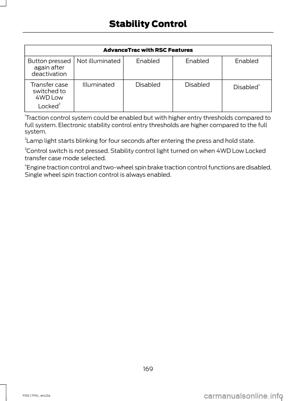
AdvanceTrac with RSC Features
Enabled
Enabled
Enabled
Not illuminated
Button pressed
again after
deactivation
Disabled4
Disabled
Disabled
Illuminated
Transfer case
switched to 4WD Low
Locked 3
1 Traction control system could be enabled but with higher entry thresholds compared to
full system. Electronic stability control entry thresholds are higher compared to the full
system.
2 Lamp light starts blinking for four seconds after entering the press and hold state.
3 Control switch is not pressed. Stability control light turned on when 4WD Low Locked
transfer case mode selected.
4 Engine traction control and two-wheel spin brake traction control functions are disabled.
Single wheel spin traction control is always enabled.
169
F150 (TF6) , enUSA Stability Control
Page 175 of 472

PARKING AID (IF EQUIPPED)
WARNINGS
To help avoid personal injury, please
read and understand the limitations
of the system as contained in this
section. Sensing is only an aid for some
(generally large and fixed) objects when
moving in reverse on a flat surface at
parking speeds. Traffic control systems,
inclement weather, air brakes, and external
motors and fans may also affect the
function of the sensing system; this may
include reduced performance or a false
activation. To help avoid personal injury, always
use caution when in R (Reverse) and
when using the sensing system.
This system is not designed to
prevent contact with small or moving
objects. The system is designed to
provide a warning to assist the driver in
detecting large stationary objects to avoid
damaging the vehicle. The system may not
detect smaller objects, particularly those
close to the ground. Certain add-on devices such as large
trailer hitches, bike or surfboard racks
and any device that may block the
normal detection zone of the system, may
create false beeps. Note:
Keep the sensors, located on the
bumper or fascia, free from snow, ice and
large accumulations of dirt. If the sensors
are covered, the system ’s accuracy can be
affected. Do not clean the sensors with
sharp objects.
Note: If your vehicle sustains damage to
the bumper or fascia, leaving it misaligned
or bent, the sensing zone may be altered
causing inaccurate measurement of
obstacles or false alarms. Note:
If your vehicle is equipped with
MyKey ™, it is possible to prevent turning
the sensing system off. See MyKey ™
(page
53).
Note: If your vehicle is equipped with a fully
integrated electronic trailer brake controller
(TBC) and a trailer with electric trailer
brakes is connected to your vehicle, the RSS
will be disabled. When the vehicle is shifted
into reverse, the information display will
remain in the Rear Park Aid Off selection.
For more information on the TBC, See
Trailer Sway Control
(page 192).
The sensing system warns the driver of
obstacles within a certain range of the
bumper area. The system turns on
automatically whenever the ignition is
switched on.
When receiving a detection warning, the
radio volume is reduced to a
predetermined level. After the warning
goes away, the radio volume returns to the
previous level.
Rear Sensing System
The rear sensors are only active when the
transmission is in R (Reverse). As the
vehicle moves closer to the obstacle, the
rate of the audible warning increases.
When the obstacle is fewer than 12 inches
(30 centimeters) away, the warning
sounds continuously. If a stationary or
receding object is detected farther than 12
inches (30 centimeters) from the side of
the vehicle, the tone sounds for only three
seconds. Once the system detects an
object approaching, the warning sounds
again.
172
F150 (TF6) , enUSA Parking Aids
Page 189 of 472
be: 635 kilograms - (2 x 99
kilograms) - (12 x 45 kilograms) =
635 - 198 - 540 = -103 kilograms.
You will need to reduce the load
weight by at least 240 pounds
(104 kilograms). If you remove
three 100-pound (45-kilogram)
cement bags, then the load
calculation would be:1400 - (2 x
220) - (9 x 100) = 1400 - 440 -
900 = 60 pounds. Now you have
the load capacity to transport the
cement and your friend home. In
metric units, the calculation would
be: 635 kilograms - (2 x 99
kilograms) - (9 x 45 kilograms) =
635 - 198 - 405 = 32 kilograms.
The above calculations also
assume that the loads are
positioned in your vehicle in a
manner that does not overload
the Front or the Rear Gross Axle
Weight Rating specified for your
vehicle on the Safety Compliance
Certification Label. The label shall
be affixed to either the door hinge
pillar, door-latch post, or the door
edge that meets the door-latch
post, next to the driver's seating
position.
Special Loading Instructions
for Owners of Pick-up Trucks
and Utility-type Vehicles WARNING
Loaded vehicles may handle
differently than unloaded
vehicles. Extra precautions, such
as slower speeds and increased
stopping distance, should be
taken when driving a heavily
loaded vehicle. Your vehicle can haul more cargo
and people than most passenger
cars. Depending upon the type
and placement of the load,
hauling cargo and people may
raise the center of gravity of the
vehicle.
TAILGATE
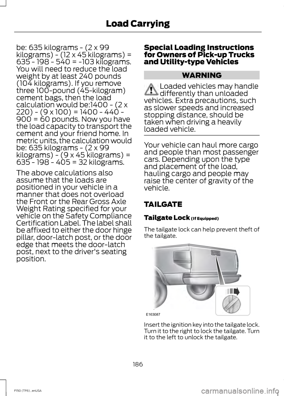
Tailgate Lock (If Equipped)
The tailgate lock can help prevent theft of
the tailgate. Insert the ignition key into the tailgate lock.
Turn it to the right to lock the tailgate. Turn
it to the left to unlock the tailgate.
186
F150 (TF6) , enUSA Load CarryingE163087
Page 191 of 472

Opening the Step
Note:
Make sure to close and fully latch the
step before moving your vehicle. Never drive
with the step or grab handle open.
1. Lower the tailgate.
2. Pull the yellow lever on the grab handle
to the unlock position. 3. Raise the handle upright until you feel
it latch and see the lever in the lock
position. You only need to use the lever
when releasing the grab handle. 4. Rotate the center molding to unlatch
the step. Pull it toward you to extend
it.
5. Open the step panel to widen the step.
Note: Do not tow with the step or grab
handle. Replace the slip resistance tape or grab
handle molding if it appears worn or
damaged.
Closing the Step
1. Close the step panel then lift and fully
close the step into the tailgate.
2. Move the yellow lever on the grab handle to the unlock position and lower
the handle.
Box Side Step (If Equipped)
Use the step for easier access to the trunk
bed.
Note: Do not drive with the step deployed.
Note: Do not exceed 500 pounds (227
kilograms) on the step. This includes you
plus cargo.
Note: Do not use the steps to lift the
vehicle. Only use proper jacking points.
Note: The steps may operate more slowly
in cool temperatures.
Note: The step mechanism may trap debris
such as mud, dirt, snow, ice and salt. This
may prevent the step from deploying
automatically when you press the button.
If this happens, make sure that you press
the button down and carefully pull out the
step manually. Wash off the debris with a
high-pressure car wash wand and stow the
step.
188
F150 (TF6) , enUSA Load CarryingE163093 E163094
Page 192 of 472
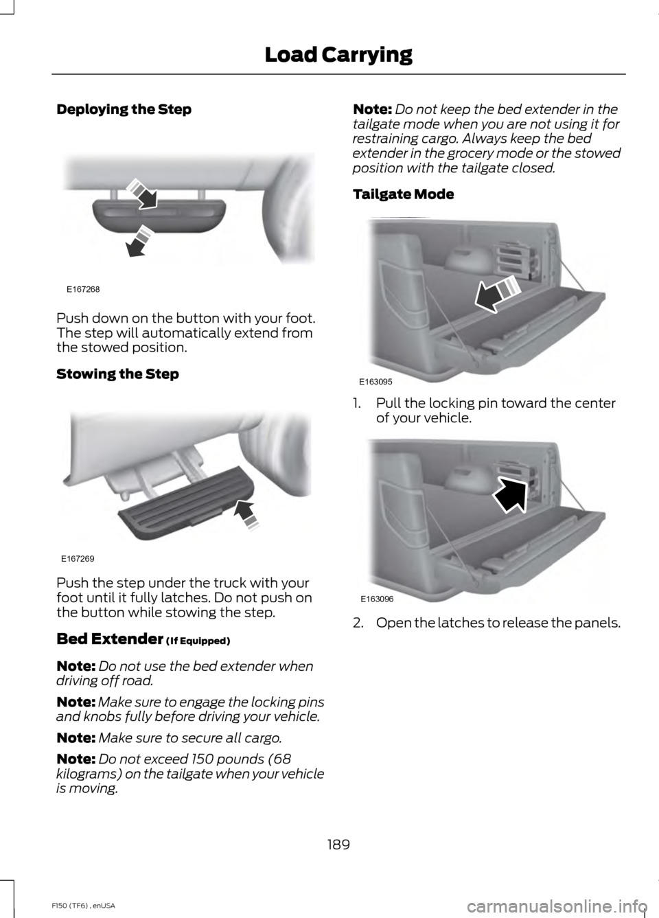
Deploying the Step
Push down on the button with your foot.
The step will automatically extend from
the stowed position.
Stowing the Step
Push the step under the truck with your
foot until it fully latches. Do not push on
the button while stowing the step.
Bed Extender (If Equipped)
Note: Do not use the bed extender when
driving off road.
Note: Make sure to engage the locking pins
and knobs fully before driving your vehicle.
Note: Make sure to secure all cargo.
Note: Do not exceed 150 pounds (68
kilograms) on the tailgate when your vehicle
is moving. Note:
Do not keep the bed extender in the
tailgate mode when you are not using it for
restraining cargo. Always keep the bed
extender in the grocery mode or the stowed
position with the tailgate closed.
Tailgate Mode 1. Pull the locking pin toward the center
of your vehicle. 2.
Open the latches to release the panels.
189
F150 (TF6) , enUSA Load CarryingE167268 E167269 E163095 E163096
Page 193 of 472
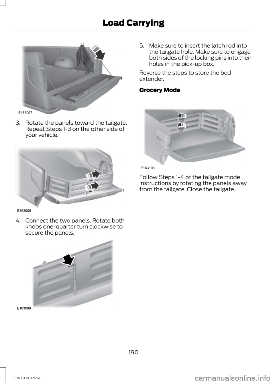
3. Rotate the panels toward the tailgate.
Repeat Steps 1-3 on the other side of
your vehicle. 4. Connect the two panels. Rotate both
knobs one-quarter turn clockwise to
secure the panels. 5. Make sure to insert the latch rod into
the tailgate hole. Make sure to engage
both sides of the locking pins into their
holes in the pick-up box.
Reverse the steps to store the bed
extender.
Grocery Mode Follow Steps 1-4 of the tailgate mode
instructions by rotating the panels away
from the tailgate. Close the tailgate.
190
F150 (TF6) , enUSA Load CarryingE163097 E163098 E163099 E163100
Page 203 of 472
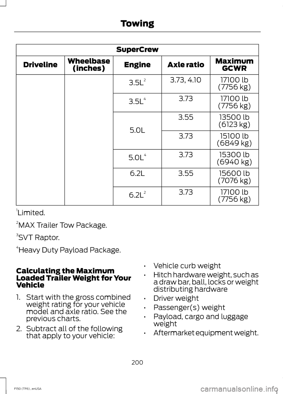
SuperCrew
MaximumGCWR
Axle ratio
Engine
Wheelbase
(inches)
Driveline
17100 lb
(7756 kg)
3.73, 4.10
3.5L 2
17100 lb
(7756 kg)
3.73
3.5L 4
13500 lb
(6123 kg)
3.55
5.0L 15100 lb
(6849 kg)
3.73
15300 lb
(6940 kg)
3.73
5.0L 4
15600 lb
(7076 kg)
3.55
6.2L
17100 lb
(7756 kg)
3.73
6.2L 2
1 Limited.
2 MAX Trailer Tow Package.
3 SVT Raptor.
4 Heavy Duty Payload Package.
Calculating the Maximum
Loaded Trailer Weight for Your
Vehicle
1. Start with the gross combined weight rating for your vehicle
model and axle ratio. See the
previous charts.
2. Subtract all of the following
that apply to your vehicle: •
Vehicle curb weight
• Hitch hardware weight, such as
a draw bar, ball, locks or weight
distributing hardware
• Driver weight
• Passenger(s) weight
• Payload, cargo and luggage
weight
• Aftermarket equipment weight.
200
F150 (TF6) , enUSA Towing
Page 205 of 472
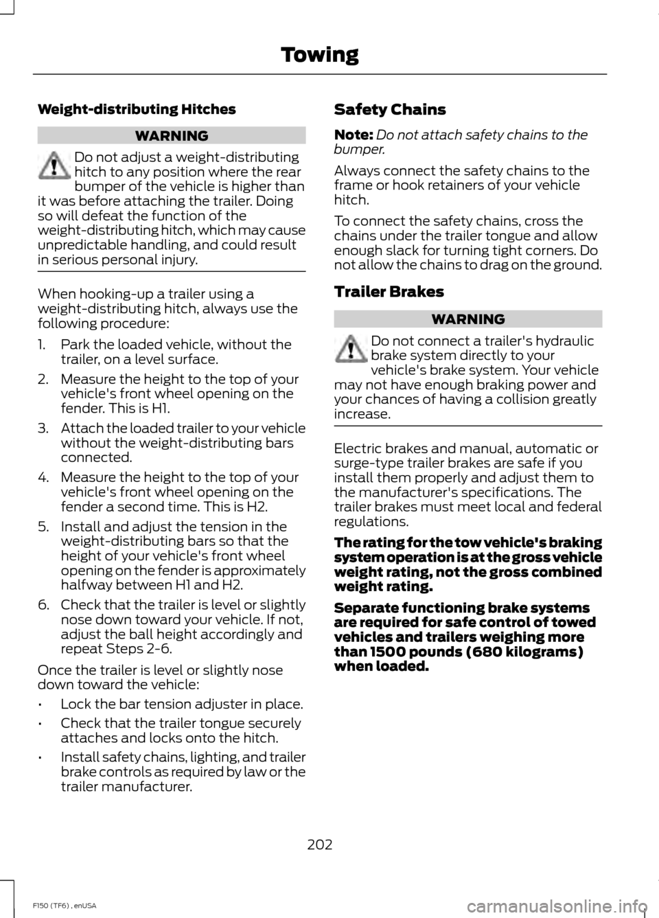
Weight-distributing Hitches
WARNING
Do not adjust a weight-distributing
hitch to any position where the rear
bumper of the vehicle is higher than
it was before attaching the trailer. Doing
so will defeat the function of the
weight-distributing hitch, which may cause
unpredictable handling, and could result
in serious personal injury. When hooking-up a trailer using a
weight-distributing hitch, always use the
following procedure:
1. Park the loaded vehicle, without the
trailer, on a level surface.
2. Measure the height to the top of your vehicle's front wheel opening on the
fender. This is H1.
3. Attach the loaded trailer to your vehicle
without the weight-distributing bars
connected.
4. Measure the height to the top of your vehicle's front wheel opening on the
fender a second time. This is H2.
5. Install and adjust the tension in the weight-distributing bars so that the
height of your vehicle's front wheel
opening on the fender is approximately
halfway between H1 and H2.
6. Check that the trailer is level or slightly
nose down toward your vehicle. If not,
adjust the ball height accordingly and
repeat Steps 2-6.
Once the trailer is level or slightly nose
down toward the vehicle:
• Lock the bar tension adjuster in place.
• Check that the trailer tongue securely
attaches and locks onto the hitch.
• Install safety chains, lighting, and trailer
brake controls as required by law or the
trailer manufacturer. Safety Chains
Note:
Do not attach safety chains to the
bumper.
Always connect the safety chains to the
frame or hook retainers of your vehicle
hitch.
To connect the safety chains, cross the
chains under the trailer tongue and allow
enough slack for turning tight corners. Do
not allow the chains to drag on the ground.
Trailer Brakes WARNING
Do not connect a trailer's hydraulic
brake system directly to your
vehicle's brake system. Your vehicle
may not have enough braking power and
your chances of having a collision greatly
increase. Electric brakes and manual, automatic or
surge-type trailer brakes are safe if you
install them properly and adjust them to
the manufacturer's specifications. The
trailer brakes must meet local and federal
regulations.
The rating for the tow vehicle's braking
system operation is at the gross vehicle
weight rating, not the gross combined
weight rating.
Separate functioning brake systems
are required for safe control of towed
vehicles and trailers weighing more
than 1500 pounds (680 kilograms)
when loaded.
202
F150 (TF6) , enUSA Towing