2014 FORD F150 ignition
[x] Cancel search: ignitionPage 219 of 472

HAZARD WARNING FLASHERS
Note:
The hazard warning flashers will
operate when the ignition is in any position
or if the key is not in the ignition. If used
when the engine is not running, the battery
will lose charge. As a result, there may be
insufficient power to restart your engine. The hazard flasher control is
located on the instrument panel
by the radio. Use it when your
vehicle is disabled and is creating a safety
hazard for other motorists.
• Press the flasher control and all front
and rear direction indicators flash.
• Press the flasher control again to turn
them off.
FUEL SHUTOFF WARNING
Failure to inspect and, if necessary,
repair fuel leaks after a collision may
increase the risk of fire and serious
injury. Ford Motor Company recommends
that the fuel system be inspected by an
authorized dealer after any collision. In the event of a moderate to severe
collision, this vehicle is equipped with a
fuel pump shut-off feature that stops the
flow of fuel to the engine. Not every impact
will cause a shut-off.
Should your vehicle shut off after a
collision, you may restart your vehicle. For
vehicles equipped with a key system:
1. Switch off the ignition.
2. Switch on the ignition.
3. Repeat Steps 1 and 2 to re-enable the
fuel pump. For vehicles equipped with a push button
start system:
1. Press the START/STOP button to
switch off the ignition.
2. Press the brake pedal and press the START/STOP
button to start the
vehicle.
3. Remove your foot from the brake pedal
and press the
START/STOP button
to switch off the ignition.
4. You can either attempt to start the engine by pressing the brake pedal and
the
START/STOP button, or switch
on the ignition only by pressing the
START/STOP
button without
pressing the brake pedal. Both ways
re-enable the fuel system.
Note: When you try to restart your vehicle
after a fuel shutoff, the vehicle makes sure
that various systems are safe to restart.
Once your vehicle determines that the
systems are safe, then the vehicle will allow
you to restart.
Note: In the event that your vehicle does
not restart after your third attempt, contact
an authorized dealer.
JUMP STARTING THE VEHICLE WARNINGS
The gases around the battery can
explode if exposed to flames, sparks,
or lit cigarettes. An explosion could
result in personal injury or vehicle damage. Batteries contain sulfuric acid which
can burn skin, eyes and clothing, if
contacted.
Use only an adequate-sized cable
with insulated clamps.
216
F150 (TF6) , enUSA Roadside EmergenciesE142663
Page 232 of 472

Protected components
Fuse amp rating
Fuse or relay number
Driver power seat/memory module
30A*
74
Powertrain control module – voltage
power 1 (3.7L, 5.0L, 6.2L engines)
15A**
75
Powertrain control module – voltage
power 1 (3.5L engine)
25A**
Powertrain control module – Voltage
power 2: General powertrain components
(Mass air flow/Intake air temp sensor -
3.7L, 5.0L, 6.2L engines) (Canister vent
solenoid - 3.5L engine)
20A**
76
Powertrain control module – Voltage
power 3 (Emission related powertrain
components, Electric fan relays coil)
10A**
77
Powertrain control module – Voltage
power 4 – Ignition coils (3.5L, 3.7L, 5.0L
engines)
15A**
78
Powertrain control module – Voltage
power 4 – Ignition coils (6.2L engine)
20A**
Rain sensor
5A**
79
Not used
—
80
Not used
—
81
Not used
—
82
Not used
—
83
Not used
—
84
Electric fan (low speed)
Relay
85
*Cartridge fuses
**Mini fuses
Passenger Compartment Fuse
Panel
The fuse panel is in the right-hand side of
the passenger footwell behind a trim panel. To remove the trim panel, pull it toward
you and swing it away from the side. To
reinstall it, line up the tabs with the grooves
on the panel, and then push it shut.
To remove the fuse panel cover, press in
the tabs on both sides of the cover, and
then pull it off.
229
F150 (TF6) , enUSA Fuses
Page 234 of 472

Protected components
Fuse amp rating
Fuse or relay number
Run/accessory relay
10A
10
Instrument cluster
10A
11
Interior lighting, Puddle lamps, Back-
lighting, Cargo lamp
15A
12
Right turn signals/stop lamps
15A
13
Left turn signals/stop lamps
15A
14
Reverse lights, High-mounted stop lamp
15A
15
Right low-beam headlamp
10A
16
Left low-beam headlamp
10A
17
Brake-shift interlock, Keypad illumination,
Powertrain control module wake-up,
Passive anti-theft system
10A
18
Audio amplifier
20A
19
Power door locks
20A
20
Not used (spare)
10A
21
Horn
20A
22
Steering wheel control module
15A
23
Datalink connector, Steering wheel control
module
15A
24
Not used (spare)
15A
25
Radio frequency module
5A
26
Not used (spare)
20A
27
Ignition switch
15A
28
Radio
20A
29
Front parking lamps
15A
30
Brake on/off – Instrument panel, Engine
5A
31
Delay/accessory – moonroof, power
windows, locks, Automatic dimming
mirror/Compass, Trailer tow power tele-
scope mirrors
15A
32
231
F150 (TF6) , enUSA Fuses
Page 252 of 472

CHECKING THE WIPER
BLADES
Run the tip of your fingers over the edge of
the blade to check for roughness.
Clean the wiper blades with washer fluid
or water applied with a soft sponge or
cloth.
CHANGING THE WIPER
BLADES
You can manually move the wiper arms
when the ignition is off. This allows for ease
of blade replacement and cleaning under
the blades.
1. Pull the wiper blade and arm away
from the glass. 2. Release the wiper blade lock (A) and
separate the wiper blade from the
wiper arm.
3. Install in the reverse order.
Note: Make sure that the wiper blade locks
into place. Lower the wiper arm and blade
back on the windshield. The wiper arms will
automatically return to their normal position
when you turn the ignition on.
• Replace wiper blades at least once per
year for optimum performance.
• You can improve poor wiper quality by
cleaning the wiper blades and the
windshield.
ADJUSTING THE HEADLAMPS
Vertical Aim Adjustment
The headlamps on your vehicle are
properly aimed at the assembly plant. If
your vehicle has been in an accident, have
the alignment of your headlamps checked
by your authorized dealer.
249
F150 (TF6) , enUSA MaintenanceE142463 E165804 A
E165794
Page 264 of 472

•
Never wash or rinse any ignition coil,
spark plug wire or spark plug well, or
the area in and around these locations.
• Cover the battery, power distribution
box, and air filter assembly to prevent
water damage when cleaning the
engine.
CLEANING THE WINDOWS AND
WIPER BLADES
Car wash chemicals and environmental
fallout can result in windshield and wiper
blade contamination. Dirty windshield and
wipers will result in poor windshield wiper
operation. Keep the windshield and wiper
blades clean to maintain windshield wiper
performance.
To clean the windshield and wiper blades:
• Clean the windshield with a
non-abrasive glass cleaner.
• For windshields contaminated with
tree sap, chemicals, wax or bugs, clean
the entire windshield using steel wool
(no greater than 0000 grade) in a
circular motion and rinse with water.
• Clean the wiper blades with isopropyl
rubbing alcohol or windshield washer
fluid.
Note: Do not use razor blades or other
sharp objects to clean or remove decals
from the inside of the heated rear window.
The vehicle warranty does not cover
damage caused to the heated rear window
grid lines.
CLEANING THE INTERIOR WARNINGS
Do not use cleaning solvents, bleach
or dye on the vehicle
’s safety belts,
as these actions may weaken the
belt webbing. WARNINGS
On vehicles equipped with
seat-mounted airbags, do not use
chemical solvents or strong
detergents. Such products could
contaminate the side airbag system and
affect performance of the side airbag in a
collision. For fabric, carpets, cloth seats, safety belts
and seats equipped with side airbags:
•
Remove dust and loose dirt with a
vacuum cleaner.
• Remove light stains and soil with
Motorcraft Professional Strength
Carpet & Upholstery Cleaner.
• If grease or tar is present on the
material, spot-clean the area first with
Motorcraft Spot and Stain Remover. In
Canada, use Motorcraft Multi-Purpose
Cleaner.
• If a ring forms on the fabric after spot
cleaning, clean the entire area
immediately (but do not oversaturate)
or the ring will set.
• Do not use household cleaning
products or glass cleaners, which can
stain and discolor the fabric and affect
the flame retardant abilities of the seat
materials.
CLEANING THE INSTRUMENT
PANEL AND INSTRUMENT
CLUSTER LENS WARNING
Do not use chemical solvents or
strong detergents when cleaning the
steering wheel or instrument panel
to avoid contamination of the airbag
system. 261
F150 (TF6) , enUSA Vehicle Care
Page 291 of 472

•
To reduce the chances of interference
from another vehicle, perform the
system reset procedure at least three
feet (one meter) away from another
Ford Motor Company vehicle
undergoing the system reset procedure
at the same time.
• Do not wait more than two minutes
between resetting each tire sensor or
the system will time-out and the entire
procedure will have to be repeated on
all four wheels.
• A double horn will sound indicating the
need to repeat the procedure.
Performing the System Reset Procedure
Read the entire procedure before
attempting.
1. Drive the vehicle above 20 mph (32 km/h) for at least two minutes, then
park in a safe location where you can
easily get to all four tires and have
access to an air pump.
2. Place the ignition in the off position and
keep the key in the ignition.
3. Cycle the ignition to the on position with the engine off.
4. Turn the hazard flashers on then off three times. You must accomplish this
within 10 seconds. If the reset mode
has been entered successfully, the horn
will sound once, the system indicator
will flash and a message is shown in
the information display. If this does not
occur, please try again starting at Step
2. If after repeated attempts to enter
the reset mode, the horn does not
sound, the system indicator does not
flash and no message is shown in the
information display, seek service from
your authorized dealer. 5. Train the tire pressure monitoring
system sensors in the tires using the
following system reset sequence
starting with the left front tire in the
following clockwise order: Left front
(driver's side front tire), Right front
(passenger's side front tire), Right rear
(passenger's side rear tire), Left rear
(driver's side rear tire)
6. Remove the valve cap from the valve stem on the left front tire. Decrease the
air pressure until the horn sounds.
Note: The single horn chirp confirms
that the sensor identification code has
been learned by the module for this
position. If a double horn is heard, the
reset procedure was unsuccessful, and
you must repeat it.
7. Remove the valve cap from the valve stem on the right front tire. Decrease
the air pressure until the horn sounds.
8. Remove the valve cap from the valve stem on the right rear tire. Decrease the
air pressure until the horn sounds.
9. Remove the valve cap from the valve stem on the left rear tire. Decrease the
air pressure until the horn sounds.
Training is complete after the horn
sounds for the last tire trained (driver's
side rear tire), the system indicator
stops flashing, and a message is shown
in the information display.
10. Turn the ignition off. If two short horn
beeps are heard, the reset procedure
was unsuccessful and you must
repeat it. If after repeating the
procedure and two short beeps are
heard when the ignition is turned to
off, seek assistance from your
authorized dealer.
288
F150 (TF6) , enUSA Wheels and Tires
Page 294 of 472

Tire Change Procedure
WARNINGS
When one of the front wheels is off
the ground, the transmission alone
will not prevent the vehicle from
moving or slipping off the jack, even if the
transmission selector lever is in position P. To help prevent the vehicle from
moving when you change a tire, be
sure to place the transmission
selector lever in position P, set the parking
brake and block (in both directions) the
wheel that is diagonally opposite (other
side and end of the vehicle) to the tire
being changed. Never get underneath a vehicle that
is supported only by a jack. If the
vehicle slips off the jack, you or
someone else could be seriously injured. Do not attempt to change a tire on
the side of the vehicle close to
moving traffic. Pull far enough off the
road to avoid the danger of being hit when
operating the jack or changing the wheel. Always use the jack provided as
original equipment with your vehicle.
If using a jack other than the one
provided as original equipment with your
vehicle, make sure the jack capacity is
adequate for the vehicle weight, including
any vehicle cargo or modifications. Disable the power running boards
before jacking, lifting, or placing any
object under the vehicle. Never place
your hand between the power running
board and the vehicle as extended power
running boards will retract when the doors
are closed. Failure to follow these
instructions may result in personal injury. Note:
Passengers should not remain in the
vehicle when the vehicle is being jacked. Park on a level surface, activate the hazard
flashers and set the parking brake. Then,
place the transmission selector lever in
position P and turn the engine off.
To remove the jack on Regular Cab and
SuperCab models:
Remove the wing nut and turn the jack
screw counterclockwise to release
pressure before removing the jack from the
bracket.
To remove the jack on SuperCrew
models:
1. Lift both rear seat cushions.
2. Remove the insert containing the Easy
Fuel funnel from the driver's side.
3. Remove the two small wing nuts on the passenger side.
4. Slide the plastic box toward the driver's
side and remove.
See the instruction sheet (located with the
jack) for detailed tire change instructions.
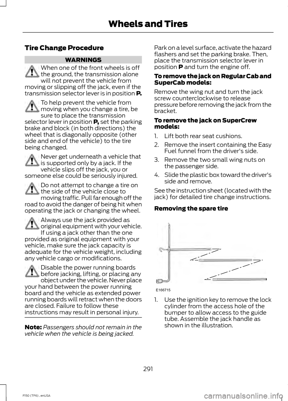
Removing the spare tire 1.
Use the ignition key to remove the lock
cylinder from the access hole of the
bumper to allow access to the guide
tube. Assemble the jack handle as
shown in the illustration.
291
F150 (TF6) , enUSA Wheels and TiresE166715
Page 299 of 472

ENGINE SPECIFICATIONS
6.2L V8
5.0L V8
3.7 V6
3.5L V6
Ecoboost
Engine
378
302
226
214
Cubic inches
Minimum 87octane
Minimum 87
octane or E85
Minimum 87
octane or E85
Minimum 87
octane
Required fuel
1-3-7-2-6-5-4-8
1-5-4-8-6-3-7-2
1-4-2-5-3-6
1-4-2-5-3-6
Firing order
Coil on plug
Coil on plug
Coil on plug
Coil on plug
Ignition
system
.041-.047 in.
(1.04-1.20 mm)
.049-.053 in.
(1.25-1.35 mm)
.049-.053 in.
(1.25-1.35 mm)
.030-.033 in.
(.75-.85 mm)
Spark plug
gap
9.8:1
10.5:1
10.5:1
10.0:1
Compression
ratio
Drivebelt Routing
3.5L V6 Ecoboost Engines with A/C 296
F150 (TF6) , enUSA Capacities and SpecificationsE167467