2014 FORD F150 clock
[x] Cancel search: clockPage 255 of 472

3. Loosen the three retaining bolts (two
at the top of the lamp, one at the lower
inboard corner).
4. Once the three retaining bolts are removed, slide the headlamp assembly
forward, disconnecting the two snap
attachments at the fender.
5. Disconnect the electrical connector from the bulb by pulling rearward. 6.
Remove the bulb and socket by turning
it counterclockwise, then pull it straight
out. 7. For the park lamp, turn lamp or side
marker lamp bulbs, disconnect the
electrical connector from the bulb by
pulling rearward, then remove the bulb
by turning it counterclockwise and
pulling it straight out.
8. Install the new bulb(s) in reverse order.
Replacing HID Headlamp Bulbs (If
Equipped)
The low beam headlamps on your vehicle
use a high intensity discharge source.
These lamps operate at a high voltage.
When you have a burned out bulb, you
must have the bulb and starter capsule
assembly replaced by an authorized dealer.
CHANGING A BULB
Lamp Assembly Condensation
Exterior lamps are vented to
accommodate normal changes in pressure.
Condensation can be a natural by-product
of this design. When moist air enters the
lamp assembly through the vents, there is
a possibility that condensation can occur
when the temperature is cold. When
normal condensation occurs, a thin film of
mist can form on the interior of the lens.
The thin mist eventually clears and exits
through the vents during normal operation.
Clearing time may take as long as 48 hours
under dry weather conditions.
252
F150 (TF6) , enUSA MaintenanceE167361 E167362 E167363
Page 256 of 472

Examples of acceptable condensation are:
•
Presence of thin mist (no streaks, drip
marks or droplets).
• Fine mist covers less than 50% of the
lens.
Examples of unacceptable moisture
(usually caused by a lamp water leak) are:
• Water puddle inside the lamp.
• Large water droplets, drip marks or
streaks present on the interior of the
lens.
Take your vehicle to a dealer for service if
any of the above conditions of
unacceptable moisture are present.
Replacing Fog Lamp Bulbs (If
Equipped 1. Make sure the headlamps are off.
2. Disconnect the electrical connector
from the fog lamp bulb.
3. Turn the bulb counterclockwise and remove it from the fog lamp.
4. Install the new bulb in reverse order.
Replacing
Brake/Tail/Turn/Reverse Lamp
Bulbs
1. Make sure the headlamps are off.
2. Open the tailgate to access the tail lamp assemblies 3. Remove the two bolts from the tail
lamp assembly. Then, carefully pull the
lamp assembly from the tailgate pillar
by releasing the two retaining tabs.
4. Disconnect the electrical connector from the bulb. 5. Rotate the bulb socket
counterclockwise and remove it from
the tail lamp assembly.
6. Install the new bulb in reverse order.
Replacing Cargo Lamp and High-
mount Brake Lamp Bulbs
1. Make sure the headlamps are off.
2. Remove the two screws and move the
lamp assembly away from the vehicle
to expose the bulb sockets.
253
F150 (TF6) , enUSA MaintenanceE163826 E167364 E167365
Page 257 of 472

3. Disconnect the electrical connector
from the bulb.
4. Remove the bulb socket by rotating it counterclockwise and pulling it out of
the lamp assembly.
5. Pull the bulb straight out of the socket.
6. Install the new bulb in reverse order.
Replacing the License Plate Lamp
Bulb
Note: The license plate bulbs are located
behind the rear bumper. 1. Reach behind the rear bumper to
locate the bulb.
2. Twist the bulb socket counterclockwise
and carefully pull to remove it from the
lamp assembly.
3. Pull the bulb straight out of the socket.
4. Install the new bulb in reverse order.
Replacing exterior mounted mirror
turn signal indicator lamp bulbs
For bulb replacement, see your authorized
dealer.
BULB SPECIFICATION CHART
Replacement bulbs are specified in the
chart below. Headlamp bulbs must be
marked with an authorized “D.O.T.” for
North America and an “E” for Europe to
ensure lamp performance, light brightness
and pattern and safe visibility. The correct
bulbs will not damage the lamp assembly
or void the lamp assembly warranty and
will provide quality bulb illumination time.
254
F150 (TF6) , enUSA MaintenanceE167366 E167368
Page 291 of 472

•
To reduce the chances of interference
from another vehicle, perform the
system reset procedure at least three
feet (one meter) away from another
Ford Motor Company vehicle
undergoing the system reset procedure
at the same time.
• Do not wait more than two minutes
between resetting each tire sensor or
the system will time-out and the entire
procedure will have to be repeated on
all four wheels.
• A double horn will sound indicating the
need to repeat the procedure.
Performing the System Reset Procedure
Read the entire procedure before
attempting.
1. Drive the vehicle above 20 mph (32 km/h) for at least two minutes, then
park in a safe location where you can
easily get to all four tires and have
access to an air pump.
2. Place the ignition in the off position and
keep the key in the ignition.
3. Cycle the ignition to the on position with the engine off.
4. Turn the hazard flashers on then off three times. You must accomplish this
within 10 seconds. If the reset mode
has been entered successfully, the horn
will sound once, the system indicator
will flash and a message is shown in
the information display. If this does not
occur, please try again starting at Step
2. If after repeated attempts to enter
the reset mode, the horn does not
sound, the system indicator does not
flash and no message is shown in the
information display, seek service from
your authorized dealer. 5. Train the tire pressure monitoring
system sensors in the tires using the
following system reset sequence
starting with the left front tire in the
following clockwise order: Left front
(driver's side front tire), Right front
(passenger's side front tire), Right rear
(passenger's side rear tire), Left rear
(driver's side rear tire)
6. Remove the valve cap from the valve stem on the left front tire. Decrease the
air pressure until the horn sounds.
Note: The single horn chirp confirms
that the sensor identification code has
been learned by the module for this
position. If a double horn is heard, the
reset procedure was unsuccessful, and
you must repeat it.
7. Remove the valve cap from the valve stem on the right front tire. Decrease
the air pressure until the horn sounds.
8. Remove the valve cap from the valve stem on the right rear tire. Decrease the
air pressure until the horn sounds.
9. Remove the valve cap from the valve stem on the left rear tire. Decrease the
air pressure until the horn sounds.
Training is complete after the horn
sounds for the last tire trained (driver's
side rear tire), the system indicator
stops flashing, and a message is shown
in the information display.
10. Turn the ignition off. If two short horn
beeps are heard, the reset procedure
was unsuccessful and you must
repeat it. If after repeating the
procedure and two short beeps are
heard when the ignition is turned to
off, seek assistance from your
authorized dealer.
288
F150 (TF6) , enUSA Wheels and Tires
Page 294 of 472

Tire Change Procedure
WARNINGS
When one of the front wheels is off
the ground, the transmission alone
will not prevent the vehicle from
moving or slipping off the jack, even if the
transmission selector lever is in position P. To help prevent the vehicle from
moving when you change a tire, be
sure to place the transmission
selector lever in position P, set the parking
brake and block (in both directions) the
wheel that is diagonally opposite (other
side and end of the vehicle) to the tire
being changed. Never get underneath a vehicle that
is supported only by a jack. If the
vehicle slips off the jack, you or
someone else could be seriously injured. Do not attempt to change a tire on
the side of the vehicle close to
moving traffic. Pull far enough off the
road to avoid the danger of being hit when
operating the jack or changing the wheel. Always use the jack provided as
original equipment with your vehicle.
If using a jack other than the one
provided as original equipment with your
vehicle, make sure the jack capacity is
adequate for the vehicle weight, including
any vehicle cargo or modifications. Disable the power running boards
before jacking, lifting, or placing any
object under the vehicle. Never place
your hand between the power running
board and the vehicle as extended power
running boards will retract when the doors
are closed. Failure to follow these
instructions may result in personal injury. Note:
Passengers should not remain in the
vehicle when the vehicle is being jacked. Park on a level surface, activate the hazard
flashers and set the parking brake. Then,
place the transmission selector lever in
position P and turn the engine off.
To remove the jack on Regular Cab and
SuperCab models:
Remove the wing nut and turn the jack
screw counterclockwise to release
pressure before removing the jack from the
bracket.
To remove the jack on SuperCrew
models:
1. Lift both rear seat cushions.
2. Remove the insert containing the Easy
Fuel funnel from the driver's side.
3. Remove the two small wing nuts on the passenger side.
4. Slide the plastic box toward the driver's
side and remove.
See the instruction sheet (located with the
jack) for detailed tire change instructions.
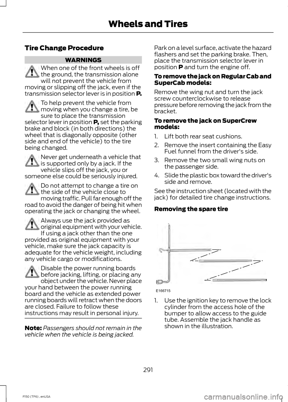
Removing the spare tire 1.
Use the ignition key to remove the lock
cylinder from the access hole of the
bumper to allow access to the guide
tube. Assemble the jack handle as
shown in the illustration.
291
F150 (TF6) , enUSA Wheels and TiresE166715
Page 295 of 472

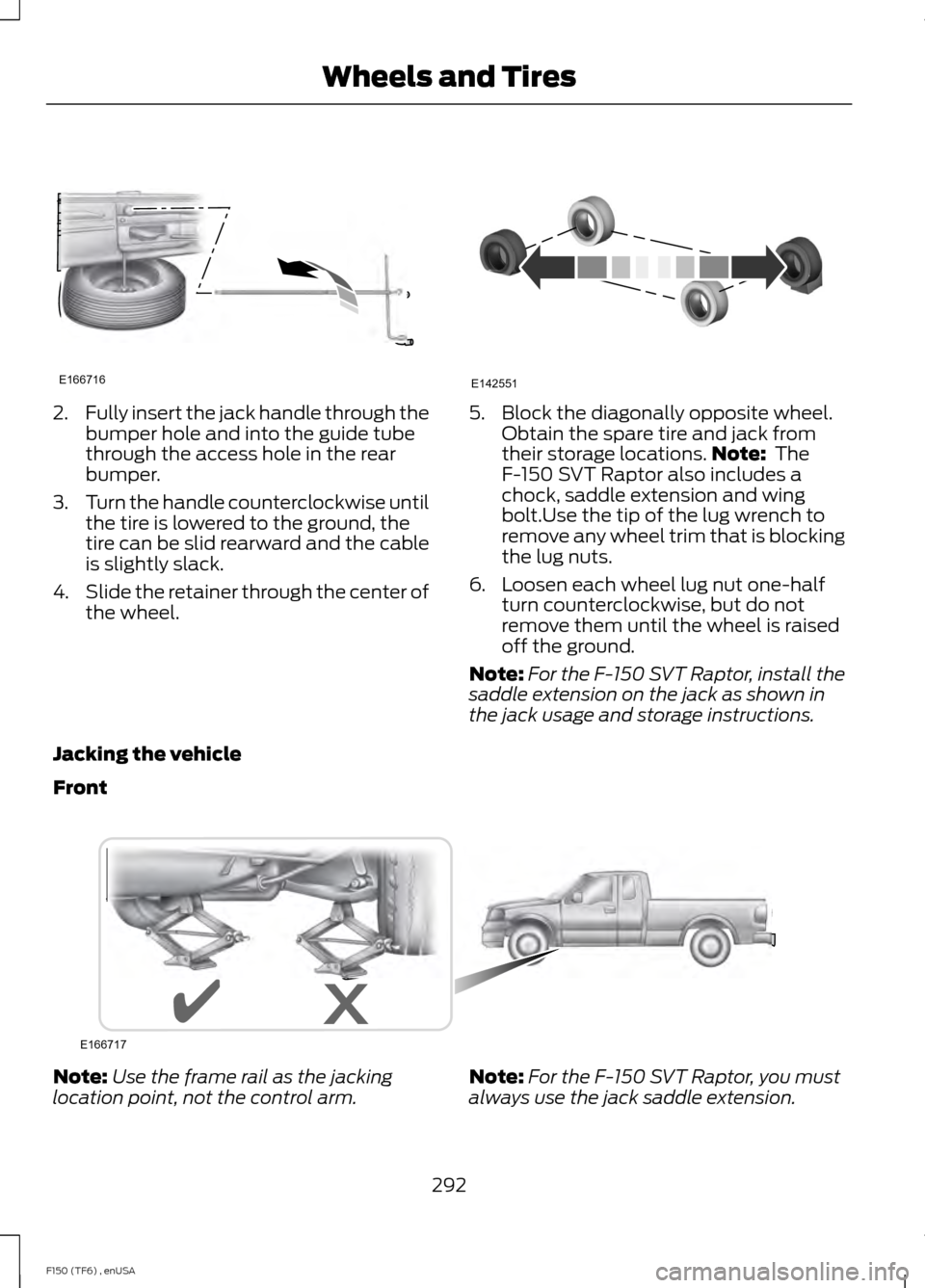
2.
Fully insert the jack handle through the
bumper hole and into the guide tube
through the access hole in the rear
bumper.
3. Turn the handle counterclockwise until
the tire is lowered to the ground, the
tire can be slid rearward and the cable
is slightly slack.
4. Slide the retainer through the center of
the wheel. 5. Block the diagonally opposite wheel.
Obtain the spare tire and jack from
their storage locations. Note: The
F-150 SVT Raptor also includes a
chock, saddle extension and wing
bolt.Use the tip of the lug wrench to
remove any wheel trim that is blocking
the lug nuts.
6. Loosen each wheel lug nut one-half turn counterclockwise, but do not
remove them until the wheel is raised
off the ground.
Note: For the F-150 SVT Raptor, install the
saddle extension on the jack as shown in
the jack usage and storage instructions.
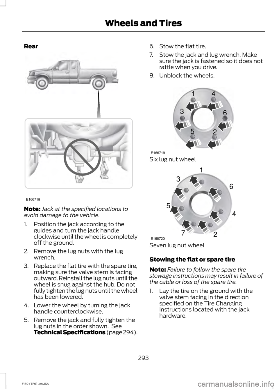
Jacking the vehicle
Front Note:
Use the frame rail as the jacking
location point, not the control arm. Note:
For the F-150 SVT Raptor, you must
always use the jack saddle extension.
292
F150 (TF6) , enUSA Wheels and TiresE166716 E142551 E166717
Page 296 of 472

Rear
Note:
Jack at the specified locations to
avoid damage to the vehicle.
1. Position the jack according to the guides and turn the jack handle
clockwise until the wheel is completely
off the ground.
2. Remove the lug nuts with the lug wrench.
3. Replace the flat tire with the spare tire,
making sure the valve stem is facing
outward. Reinstall the lug nuts until the
wheel is snug against the hub. Do not
fully tighten the lug nuts until the wheel
has been lowered.
4. Lower the wheel by turning the jack handle counterclockwise.
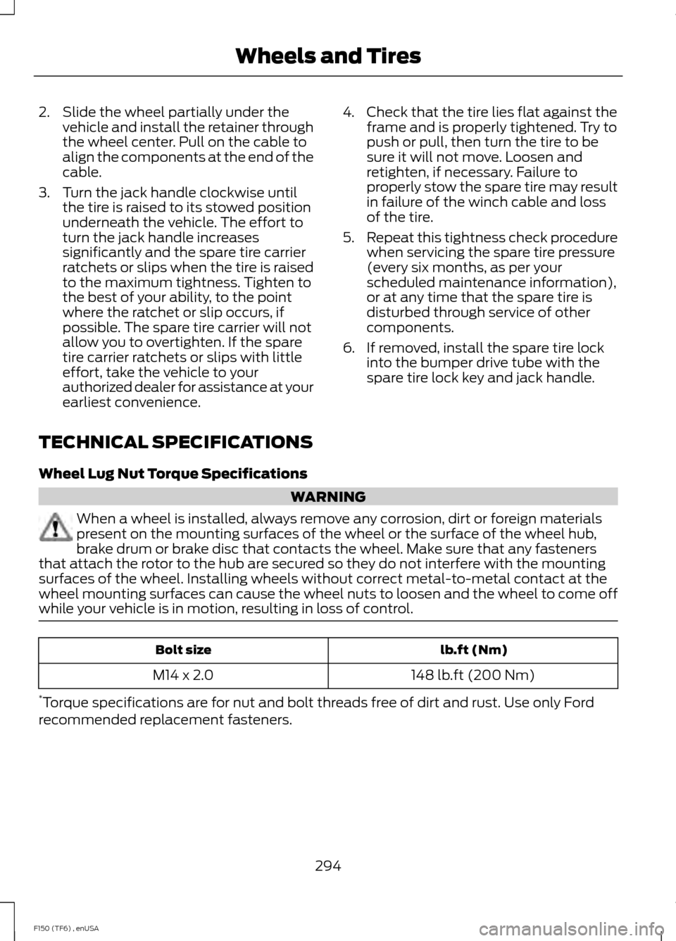
5. Remove the jack and fully tighten the lug nuts in the order shown. See
Technical Specifications (page 294). 6. Stow the flat tire.
7. Stow the jack and lug wrench. Make
sure the jack is fastened so it does not
rattle when you drive.
8. Unblock the wheels. Six lug nut wheel
Seven lug nut wheel
Stowing the flat or spare tire
Note:
Failure to follow the spare tire
stowage instructions may result in failure of
the cable or loss of the spare tire.
1. Lay the tire on the ground with the valve stem facing in the direction
specified on the Tire Changing
Instructions located with the jack
hardware.
293
F150 (TF6) , enUSA Wheels and TiresE166718 E166719
1
3
5 4
6
2 E166720
1
3
5
7 6
4
2
Page 297 of 472

2. Slide the wheel partially under the
vehicle and install the retainer through
the wheel center. Pull on the cable to
align the components at the end of the
cable.
3. Turn the jack handle clockwise until the tire is raised to its stowed position
underneath the vehicle. The effort to
turn the jack handle increases
significantly and the spare tire carrier
ratchets or slips when the tire is raised
to the maximum tightness. Tighten to
the best of your ability, to the point
where the ratchet or slip occurs, if
possible. The spare tire carrier will not
allow you to overtighten. If the spare
tire carrier ratchets or slips with little
effort, take the vehicle to your
authorized dealer for assistance at your
earliest convenience. 4. Check that the tire lies flat against the
frame and is properly tightened. Try to
push or pull, then turn the tire to be
sure it will not move. Loosen and
retighten, if necessary. Failure to
properly stow the spare tire may result
in failure of the winch cable and loss
of the tire.
5. Repeat this tightness check procedure
when servicing the spare tire pressure
(every six months, as per your
scheduled maintenance information),
or at any time that the spare tire is
disturbed through service of other
components.
6. If removed, install the spare tire lock into the bumper drive tube with the
spare tire lock key and jack handle.
TECHNICAL SPECIFICATIONS
Wheel Lug Nut Torque Specifications WARNING
When a wheel is installed, always remove any corrosion, dirt or foreign materials
present on the mounting surfaces of the wheel or the surface of the wheel hub,
brake drum or brake disc that contacts the wheel. Make sure that any fasteners
that attach the rotor to the hub are secured so they do not interfere with the mounting
surfaces of the wheel. Installing wheels without correct metal-to-metal contact at the
wheel mounting surfaces can cause the wheel nuts to loosen and the wheel to come off
while your vehicle is in motion, resulting in loss of control. lb.ft (Nm)
Bolt size
148 lb.ft (200 Nm)
M14 x 2.0
* Torque specifications are for nut and bolt threads free of dirt and rust. Use only Ford
recommended replacement fasteners.
294
F150 (TF6) , enUSA Wheels and Tires