Page 137 of 231
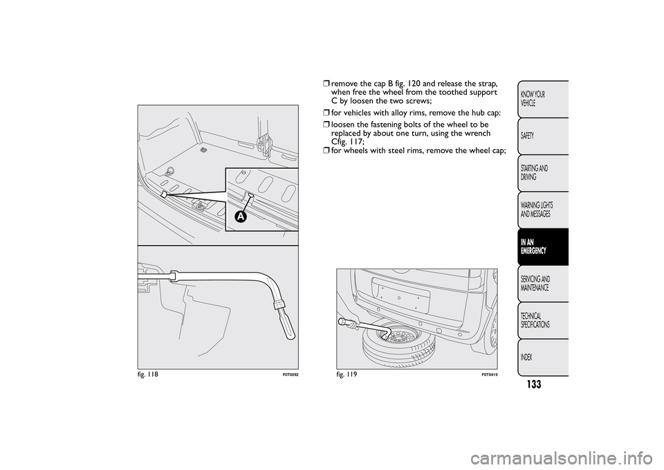
❒remove the cap B fig. 120 and release the strap,
when free the wheel from the toothed support
C by loosen the two screws;
❒for vehicles with alloy rims, remove the hub cap:
❒loosen the fastening bolts of the wheel to be
replaced by about one turn, using the wrench
Cfig. 117;
❒for wheels with steel rims, remove the wheel cap;
A
fig. 118
F0T0292
fig. 119
F0T0419
133KNOW YOUR
VEHICLE
SAFETY
STARTING AND
DRIVING
WARNING LIGHTS
AND MESSAGESIN AN
EMERGENCYSERVICING AND
MAINTENANCE
TECHNICAL
SPECIFICATIONS
INDEX
Page 138 of 231
❒turn the jack to open it partially fig. 121 and then
position it under the vehicle at the references A
fig. 122 near the wheel to be replaced;❒turn the jack to open it until the groove A fig. 123
of the jack is correctly inserted in the lower profile
B on the side member:
fig. 120
F0T0169
fig. 121
F0T0124
fig. 122
F0T0125
fig. 123
F0T0126
134KNOW YOUR
VEHICLE
SAFETY
STARTING AND
DRIVING
WARNING LIGHTS
AND MESSAGES
IN AN
EMERGENCY
SERVICING AND
MAINTENANCE
TECHNICAL
SPECIFICATIONS
INDEX
Page 139 of 231

❒warn anybody nearby that the vehicle is about to
be lifted. They must stay clear and not touch the
vehicle until it is back on the ground.
❒operate the jack and lift the vehicle until the wheel
is several centimetres off the ground. When
turning the crank, ensure that it rotates freely in
order to avoid grazing your hands against the
ground. The moving components of the jack
(screws and joints) can also cause injuries, so do
not touch them. If you become soiled with the
lubricating grease, wash it off thoroughly;❒fully loosen the fastening bolts and remove the
wheel;
❒make sure the contact surfaces between spare
wheel and hub are clean so that the fastening bolts
will not come loose;
❒fit the standard wheel by inserting the first bolt
two threads B fig. 124 into the hole closest to
the inflation valve A;
❒fit the hub cap, making sure that the symbol
(on
the cap) aligns with the inflation valve, and then
insert the other three bolts;
fig. 124
F0T0282
135KNOW YOUR
VEHICLE
SAFETY
STARTING AND
DRIVING
WARNING LIGHTS
AND MESSAGESIN AN
EMERGENCYSERVICING AND
MAINTENANCE
TECHNICAL
SPECIFICATIONS
INDEX
Page 140 of 231

❒tighten the bolts using the wrench provided;
❒for vehicles with alloy rim, fit the hub cap;
❒turn the jack handle to lower the vehicle, and
remove the jack;
❒use the wrench provided to fasten the bolts
completely in a criss-cross fashion as shown in
fig. 125.When you have finished
❒Fix the toothed support on the wheel by means of
two screws (insert in the outer wheel support).
Refit the restraining metallic wire in the seat
and refit the protective cap A fig. 126;
❒check replaced wheel positioning under the floor
(the lifting system is supplied with a clutch to
limit the end of the stroke). Incorrect positioning
may jeopardise safety;
❒lift the wheel by fastening the bolt A fig. 118;
❒put jack and tools back in the specific tool bag;
❒reposition the tool bag in the boot;
❒secure the tool box to the hooks.
fig. 125
F0T0128
fig. 126
F0T0170
136KNOW YOUR
VEHICLE
SAFETY
STARTING AND
DRIVING
WARNING LIGHTS
AND MESSAGES
IN AN
EMERGENCY
SERVICING AND
MAINTENANCE
TECHNICAL
SPECIFICATIONS
INDEX
Page 141 of 231

FIX & GO AUTOMATIC QUICK TYRE
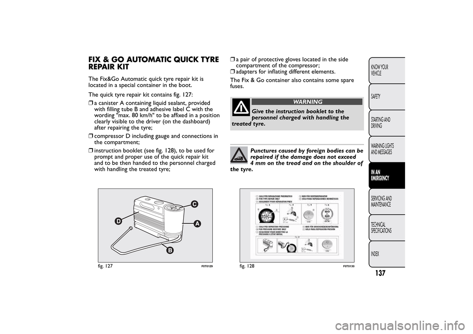
REPAIR KITThe Fix&Go Automatic quick tyre repair kit is
located in a special container in the boot.
The quick tyre repair kit contains fig. 127:
❒a canister A containing liquid sealant, provided
with filling tube B and adhesive label C with the
wording "max. 80 km/h" to be affixed in a position
clearly visible to the driver (on the dashboard)
after repairing the tyre;
❒compressor D including gauge and connections in
the compartment;
❒instruction booklet (see fig. 128), to be used for
prompt and proper use of the quick repair kit
and to be then handed to the personnel charged
with handling the treated tyre;❒a pair of protective gloves located in the side
compartment of the compressor;
❒adapters for inflating different elements.
The Fix & Go container also contains some spare
fuses.
WARNING
Give the instruction booklet to the
personnel charged with handling the
treated tyre.Punctures caused by foreign bodies can be
repaired if the damage does not exceed
4 mm on the tread and on the shoulder of
the tyre.
fig. 127
F0T0129
fig. 128
F0T0130
137KNOW YOUR
VEHICLE
SAFETY
STARTING AND
DRIVING
WARNING LIGHTS
AND MESSAGESIN AN
EMERGENCYSERVICING AND
MAINTENANCE
TECHNICAL
SPECIFICATIONS
INDEX
Page 142 of 231
WARNING
It is not possible to repair damage to the
tyre sidewall. Do not use the quick
repair kit if the tyre was damaged by running
on a flat .
WARNING
Repair is not possible if the wheel rim is
damaged (groove is deformed, causing
air to escape). Do not remove foreign bodies
(screws or nails) from the tyre.IMPORTANT INFORMATION:
The sealing fluid of the quick tyre repair kit is
effective at external temperatures of between -20°C
and +50°C.
WARNING
Do not operate the compressor for
longer than 20 minutes at a time. Risk
of overheating.The quick repair kit is not
suitable for definitive repairs, so the tyres
repaired may be used only temporarily.Dispose of the cylinder and the sealant
properly. Dispose according to the
national and local laws in force.
138KNOW YOUR
VEHICLE
SAFETY
STARTING AND
DRIVING
WARNING LIGHTS
AND MESSAGES
IN AN
EMERGENCY
SERVICING AND
MAINTENANCE
TECHNICAL
SPECIFICATIONS
INDEX
Page 143 of 231

WARNING
The cylinder contains ethyl glycol. It
contains latex, which may cause an
allergic reaction. Harmful if swallowed. Eye
irritant .There could be a reaction in the event
of inhalation or contact . Avoid contact with
the eyes, skin and clothes. In the event of
contact , rinse immediately with plenty of water.
Do not induce vomiting if swallowed. Rinse
your mouth out and drink plenty of water. Call
a doctor immediately. Keep out of the reach
of children.The product must not be used by
asthmatics. Do not breathe in the vapours
during inser tion and suction. Call a doctor
immediately if allergic reactions are noted.
Store the cylinder in its special compartment ,
away from sources of heat .The sealant has
an expiry date. Replace the cylinder containing
the sealant after the expiry date.INFLATION PROCEDURE
WARNING
Put on the safety gloves provided
together with the quick tyre repair kit .
❒Apply the handbrake. Unscrew the tyre valve cap,
take out the flexible filler pipe A fig. 129 and
tighten the ring nut B on the tyre valve;
fig. 129
F0T0190
139KNOW YOUR
VEHICLE
SAFETY
STARTING AND
DRIVING
WARNING LIGHTS
AND MESSAGESIN AN
EMERGENCYSERVICING AND
MAINTENANCE
TECHNICAL
SPECIFICATIONS
INDEX
Page 144 of 231

❒make sure that switch E fig. 131 of the compressor
is at 0 (off ), start the engine, insert plug D fig. 130
in the cigar lighter socket and turn the compressor
on by setting switch E fig. 131 to I (on). Inflate
the tyre to the pressure specified in the "Cold tyre
pressures" paragraph in the "Technical
specifications" section. For a more accurate
reading, check pressure gauge F fig. 131 with the
compressor off;
❒if after 5 minutes it is still impossible to reach at
least 1.5 bar, disengage compressor from valve
and unplug it from the socket, then move the car
forth for approx. ten metres in order to distribute
the sealing fluid inside the tyre evenly, then repeat
the inflation operation;❒if after this operation it is still impossible after 5
minutes to reach at least 1.8 bar, do not start
driving since the tyre is excessively damaged and
the quick tyre repair kit cannot guarantee suitable
sealing, contact Fiat Dealership;
❒if you do reach the tyre pressure specified in the
“Cold tyre pressures” paragraph of the “Technical
specifications” section, continue your journey
immediately;
WARNING
Apply the adhesive label where it can be
easily seen by the driver as a reminder
that the tyre has been treated with the quick
repair kit . Drive carefully, particularly on bends.
Do not exceed 80 km/h. Do not accelerate or
brake suddenly.
fig. 130
F0T0133
fig. 131
F0T0131
140KNOW YOUR
VEHICLE
SAFETY
STARTING AND
DRIVING
WARNING LIGHTS
AND MESSAGES
IN AN
EMERGENCY
SERVICING AND
MAINTENANCE
TECHNICAL
SPECIFICATIONS
INDEX