2014 FIAT 500L LIVING Warning lights
[x] Cancel search: Warning lightsPage 199 of 420
START&STOP SYSTEM FAILURE
Versions with multifunction display
Start&Stop system failure is indicated by the
switching on of the
warning light (for versions/
markets, where provided) on the instrument panel
and a message on the display.
Versions with reconfigurable multifunction
display
The
symbol and a dedicated message appear on
the display when a failure in the Start&Stop system is
detected.
In the event of a Start&Stop system failure, contact a
Fiat Dealership.TRACTION PLUS SYSTEM
ACTIVATION/DEACTIVATION
(for versions/markets, where provided)
Traction Plus system activation/deactivation by
pressing the corresponding button (see the "Traction
Plus system" paragraph in the "Knowing your car"
section) is indicated by a message on the display.
195GETTING TO KNOW
YOUR CAR
SAFETY
STARTING AND
DRIVINGWARNING LIGHTS
AND MESSAGESIN AN EMERGENCY
SERVICING AND
MAINTENANCE
TECHNICAL
SPECIFICATIONS
INDEX
Page 200 of 420
IN AN EMERGENCY
In an emergency we recommend that you call the free-phone number found on the Warranty
Booklet.You can also go to the www.fiat.com website to find your nearest Fiat Dealership.STARTING THE ENGINEContact to a Fiat Dealership immediately if
instrument panel warning light
comes on
constantly.
JUMP STARTING
If the battery is flat, the engine may be started using
an auxiliary battery with the same capacity or a
little higher than the flat one.Proceed as follows to start the car:
❒connect the positive terminals (+near the
terminal) of the two batteries with a jump lead
fig. 153;
❒with a second lead, connect the negative terminal
–of the auxiliary battery to an earth point
on
the engine or the gearbox of the car to be started;
❒start the engine;
❒when the engine has been started, remove the
leads reversing the order above.
For versions with Start&Stop system, to carry out
the jump starting procedure, refer to the paragraph
“Start&Stop system” in the “Getting to know your
car” section.
If after a few attempts the engine does not start, do
not persist but contact a Fiat Dealership.
IMPORTANT Do not directly connect the negative
terminals of the two batteries: sparks could ignite
explosive gas released from the battery. If the
auxiliary battery is installed on another car, prevent
accidental contact between metallic parts of the two
cars.
fig. 153
F0Y0137
196GETTING TO KNOW
YOUR CAR
SAFETY
STARTING AND
DRIVING
WARNING LIGHTS
AND MESSAGES
IN AN
EMERGENCY
SERVICING AND
MAINTENANCE
TECHNICAL
SPECIFICATIONS
INDEX
Page 201 of 420
Never use a fast batter y-charger to star t
the engine as this could damage the
electronic systems of your car, particularly
the ignition and fuel supply control units.
WARNING
This procedure must be performed by
expert personnel because incorrect
actions could cause electrical discharge of
considerable intensity. Furthermore, battery
fluid is poisonous and corrosive: avoid contact
with skin and eyes. Keep naked flames and
lighted cigarettes away from the battery and do
not cause sparks.
BUMP STARTING
Never jump start the engine by pushing, towing or
coasting downhill.
IMPORTANT Remember that the brake servo and
electrical power steering system are not active until
the engine is started. A much greater effort will
therefore be required to use the brake pedal or turn
the steering wheel.
REPLACING A WHEELGENERAL INSTRUCTIONS
The car is equipped with the "Fix&Go Automatic
Kit": see the paragraph “Fix&Go Automatic Kit” for
how to use this device.
As an alternative to the “Fix&Go Automatic Kit” the
car may be equipped with a space-saver wheel: see
the instructions on the following pages for changing
the wheel.
WARNING
The space-saver wheel (for versions/
markets where provided) is specific to
your car, do not use it on other models, or use
the space-saver wheel of other models on your
car.The space-saver wheel must only be used
in case of emergency. It must only be used
for the distance necessary to reach a service
point and the car speed must not exceed 80
km/h.The space-saver wheel has an orange
sticker that summarises the main cautions for
use and limitations. Never remove or cover
the label.The following information is provided
in four languages on the label: "Important!
For temporary use only! 80 km/h max! Replace
with a standard tyre as soon as possible. Never
cover this indication." Never apply a hub cap on
a space-saver wheel.
197GETTING TO KNOW
YOUR CAR
SAFETY
STARTING AND
DRIVING
WARNING LIGHTS
AND MESSAGESIN AN
EMERGENCYSERVICING AND
MAINTENANCE
TECHNICAL
SPECIFICATIONS
INDEX
Page 202 of 420
WARNING
Alert other drivers that the car is
stationary in compliance with local
regulations: hazard warning lights, warning
triangle, etc . Any passengers on board should
leave the car, especially if it is heavily laden.
Passengers should stay away from on-coming
traffic while the wheel is being changed. If you
are on a slope or uneven surface, place the
wedge provided under the wheel (see the
instructions on the next pages).
WARNING
The vehicle's driving characteristics will
be modified with the space-saver wheel
fitted. Avoid sudden starting or stopping, sharp
or fast turns.The overall duration of the
space-saver spare wheel is of about 3000 km,
after which the relevant tyre must be replaced
with another one of the same type. Never
install a standard tyre on a rim that is designed
for use with a space-saver wheel. Have the
wheel repaired and refitted as soon as possible.
Two or more space-saver wheels should never
be used together. Do not grease the threads
of wheel studs before fitting them: they might
slip out .
WARNING
The jack shall only be used for raising
the car model it has been supplied with.
Never use the jack for other purposes, such as
raising other car models. Never use the jack for
repair operations under the vehicle. Incorrectly
positioning the jack may cause the vehicle to
fall. Do not use the jack for loads higher than
the one shown on its label.The space-saver
wheel cannot be fitted with snow chains. If a
front (drive) tyre is punctured and chains are
needed, use a standard wheel from the rear
axle and install the space-saver wheel on the
rear axle. In this way, with two normal drive
wheels at the front axle, it is possible to use
snow chains.
WARNING
Incorrectly fitting the wheel cap may
cause it to fall off when the vehicle is in
motion. Never tamper with the inflating valve.
Never introduce tools of any kind between
rim and tyre. Check tyre and space-saver wheel
pressures regularly, complying with the values
given in the "Technical specifications" chapter.
198GETTING TO KNOW
YOUR CAR
SAFETY
STARTING AND
DRIVING
WARNING LIGHTS
AND MESSAGES
IN AN
EMERGENCY
SERVICING AND
MAINTENANCE
TECHNICAL
SPECIFICATIONS
INDEX
Page 203 of 420
JACK
Please note that:
❒the jack weight is 1,76 kg;
❒the jack requires no adjustment;
❒the jack cannot be repaired and in the event of a
fault it must be replaced by another original one;
❒no tool other than its cranking device may be
fitted on the jack.
To change a wheel, proceed as follows:
❒Stop the car in a position that is not dangerous for
oncoming traffic where you can change the wheel
safely. The ground must be flat and sufficiently
compact;
❒switch off the engine, pull up the handbrake and
engage the 1
stgear or reverse. Wear the reflective
safety jacket (compulsory by law) before getting
out of the car;
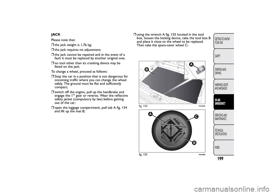
❒open the luggage compartment, pull tab A fig. 154
and lift up the mat B;❒using the wrench A fig. 155 located in the tool
box, loosen the locking device, take the tool box B
and place it close to the wheel to be replaced.
Then take the space-saver wheel C;
fig. 154
F0Y0083
fig. 155
F0Y0096
199GETTING TO KNOW
YOUR CAR
SAFETY
STARTING AND
DRIVING
WARNING LIGHTS
AND MESSAGESIN AN
EMERGENCYSERVICING AND
MAINTENANCE
TECHNICAL
SPECIFICATIONS
INDEX
Page 204 of 420
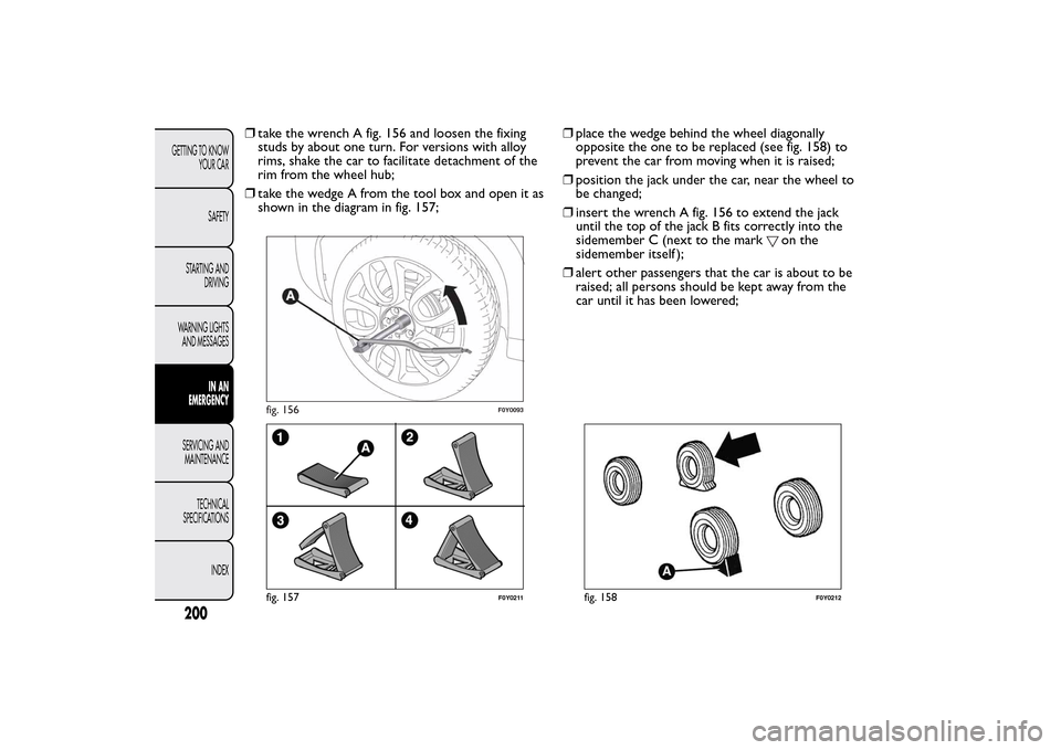
❒take the wrench A fig. 156 and loosen the fixing
studs by about one turn. For versions with alloy
rims, shake the car to facilitate detachment of the
rim from the wheel hub;
❒take the wedge A from the tool box and open it as
shown in the diagram in fig. 157;❒place the wedge behind the wheel diagonally
opposite the one to be replaced (see fig. 158) to
prevent the car from moving when it is raised;
❒position the jack under the car, near the wheel to
be changed;
❒insert the wrench A fig. 156 to extend the jack
until the top of the jack B fits correctly into the
sidemember C (next to the mark
on the
sidemember itself );
❒alert other passengers that the car is about to be
raised; all persons should be kept away from the
car until it has been lowered;
fig. 156
F0Y0093
fig. 157
F0Y0211
fig. 158
F0Y0212
200GETTING TO KNOW
YOUR CAR
SAFETY
STARTING AND
DRIVING
WARNING LIGHTS
AND MESSAGES
IN AN
EMERGENCY
SERVICING AND
MAINTENANCE
TECHNICAL
SPECIFICATIONS
INDEX
Page 205 of 420
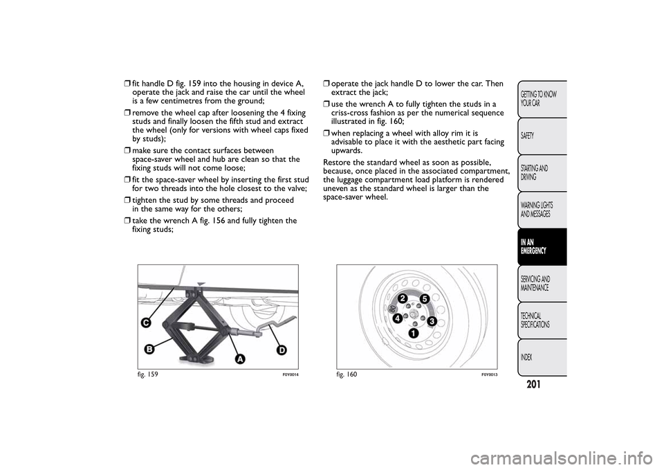
❒fit handle D fig. 159 into the housing in device A,
operate the jack and raise the car until the wheel
is a few centimetres from the ground;
❒remove the wheel cap after loosening the 4 fixing
studs and finally loosen the fifth stud and extract
the wheel (only for versions with wheel caps fixed
by studs);
❒make sure the contact surfaces between
space-saver wheel and hub are clean so that the
fixing studs will not come loose;
❒fit the space-saver wheel by inserting the first stud
for two threads into the hole closest to the valve;
❒tighten the stud by some threads and proceed
in the same way for the others;
❒take the wrench A fig. 156 and fully tighten the
fixing studs;❒operate the jack handle D to lower the car. Then
extract the jack;
❒use the wrench A to fully tighten the studs in a
criss-cross fashion as per the numerical sequence
illustrated in fig. 160;
❒when replacing a wheel with alloy rim it is
advisable to place it with the aesthetic part facing
upwards.
Restore the standard wheel as soon as possible,
because, once placed in the associated compartment,
the luggage compartment load platform is rendered
uneven as the standard wheel is larger than the
space-saver wheel.
fig. 159
F0Y0014
fig. 160
F0Y0013
201GETTING TO KNOW
YOUR CAR
SAFETY
STARTING AND
DRIVING
WARNING LIGHTS
AND MESSAGESIN AN
EMERGENCYSERVICING AND
MAINTENANCE
TECHNICAL
SPECIFICATIONS
INDEX
Page 206 of 420
REFITTING THE STANDARD WHEEL
Following the procedure described previously, raise
the car and remove the space-saver wheel.
Versions with steel rims
Proceed as follows:
❒make sure the contact surfaces between standard
wheel and hub are clean so that the fixing studs
will not come loose;
❒fit the standard wheel inserting the 5 studs into
the holes;
❒press-fit the hub cap, aligning the special splining
(on the cap) with the inflation valve;
❒using the wrench provided, tighten the fixing studs;
❒lower the car and remove the jack;
❒using the wrench provided, fully tighten the studs
in the sequence shown previously.Versions with alloy wheels
Proceed as follows:
❒insert the wheel on the hub and using the wrench
provided tighten the studs;
❒lower the car and remove the jack;
❒using the wrench provided, fully tighten the 5 studs
in the sequence shown;
❒reinstall the hub cap, taking care to position the 3
plastic pins in the dedicated seats on the wheel.
Slightly press the cap to prevent any damage to the
plastic pins.
IMPORTANT If it is not fitted properly, the hub cap
may detach itself when the car is running.
After tyre replacement
❒stow the space-saver wheel in the compartment
provided in the boot;
❒insert the jack and the other tools in the
container;
❒arrange the container and tools on the space-saver
wheel;
❒correctly reposition the boot stiff cover.
202GETTING TO KNOW
YOUR CAR
SAFETY
STARTING AND
DRIVING
WARNING LIGHTS
AND MESSAGES
IN AN
EMERGENCY
SERVICING AND
MAINTENANCE
TECHNICAL
SPECIFICATIONS
INDEX