Page 129 of 314

long side of the blue surface so that there is
suff icient space from the obstacle. The sur
face must not be touch ing. You will also need
to start turning the steer ing whee l much ear
lier. The blue curve
¢ fig . 13 7 must not to uch
the obstacle and should have sufficient room .
@ Tips
The left or right orientation lines and sur
faces will be displayed, depend ing on the
turn signa l bei ng used.
Peripheral cameras
Introduction
Applies to vehicles: with top view camera system
In addit ion to the functions from the sensors
¢ page 123, Sensors,¢ page 125 , Visual dis
play,
this parking system conta ins peripheral
cameras. Depending on the ve hicle equip
ment, you are assis ted by various views such
as peripheral view, corner views at the front
and rear of the veh icle, and views d irectly in
fro nt of o r behind the vehicle.
General information
App lies to vehicles: with top view camera system
Fig. 138 Loca tion of per ipheral came ras
Depending on the vehicle equ ipment, the pe
riphera l cameras are fou nd i n the radiator
grille, in the luggage compartment lid and on both exterior mirrors ¢
fig. 138 . Make sure
that the lenses are no t covered by deposits or
any other obstructions as it may impair the
sys tem. For information on cleaning, refer to
¢ page 216.
P arking sys tems 127
In the to p view mode, b lack corners are
shown in the ve hicle silhouette . Objects in
these areas are outside of the camera 's field
of view and are not detected .
T he accuracy of the orientation lines and the
bl ue surfaces is reduced if the adaptive air
suspension * is faulty, if the vehicle is lifted or
if the
dynamic mode is activated ¢ page 110.
A WARNING
- Always read and follow the applicable
warn ings ¢
& in General information on
page 122.
- If the position or the installat io n angle
of a camera was changed , after a colli
sion for example, do not continue to use
the system fo r safety reaso ns. Have i t
checked by you r author ized Audi dealer
sh ip .
- Keep in mind tha t the image in the dis
pl ay is distorte d if the exterior mirror
housing has bee n manually a dju sted .
- Use the
rear mode and the c orner view
( rear )
mode only when the luggage com
partment lid is fu lly closed . Otherwise
the image in the disp lay will be d istort
ed .
- T he vehicle surro undings are shown us
ing the came ra images. The veh icle im
age is shown by the system. Objects and
obstacles above the camera are not d is
p layed.
- Camera lenses enlarge and distort the fie ld of vision . T he objects appear both
altered and inaccurate on the sc reen.
(D Note
- Always read and follow the ap plicable
warnings
¢(Din General information on
page 122.
- The Infotainment d isp lay shows the di
rection in which the rear of the vehicle is
traveling based on the steer ing whee l
ang le . The front of the vehicle front
swings out more than the rear of the ve
hicle . Maintain plenty of d istance so that
IJJ,,
Page 130 of 314

128 Parking systems
your outside mirror or a corner of your
vehicle does not collide with any obsta
cles.
@ Tips
If the 8/o;iJ/c:::::5 symbol appears in the
disp lay and the respectiv e display area is
grayed out, then the power exter ior mir
rors were folded in or the dr iver's door/
front passenger's door/luggage compart
ment lid was opened.
Switching on or off
App lies to vehicles: with top view camera system
Fi g. 139 Center consol e: P
Fig. 14 0 In fotainmen t: se lect ing t he mode
Switching on
• Shift in to reve rse, or
> Press the P, qi b utton in the center console
¢
fig . 139 . A short confirmat ion tone
sounds and the LED in the button turns on .
Selecting the mode
• Turn the contro l knob to the symbol for the
desired mode @thro ugh
© ¢fig. 140.
ll Th e c am era im age is n ot s hown fo r all ve rsi on s.
Switching off
• Dr ive fo rward faster than 6 mph (10 km/ h),
or
• Press the
P, JJi button, or
• Switch the ignition off .
You may select from the following modes:
@ -Top view* ¢
page 128
@-Corner view (front)* ¢ page 129
© -Front * ¢ page 129
@ -Rea r* ¢
page 129
© -Corner view (rear)* ¢ page 129
Top view
Applies to vehicles : w it h top v iew camera system and top
v iew mode
F ig . 14 1 In fota inm ent : top v iew m ode
This view is idea l for maneuver ing. The veh icle
surround ings a re shown us ing the camera im
ages . The vehicle image is shown by the sys
tem.
Selecting top view
"' Select the@symbo l w ith th e control knob .
Switching between optical view and
camera imagel)
"'To display the came ra image, press the c am
era
control button @.
"' Press the
Graphi c control button to see the
optical d isp lay.
Page 131 of 314

Corner view (front/rear)
Applies to vehicles: with top view camera system and cor
ner view (front/rear) mode
Fig. 1 42 Infotainment : corner view (front) mode
Fig. 1 43 Infota inment : co m er view (rear) mode
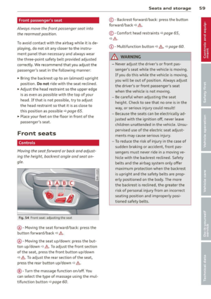
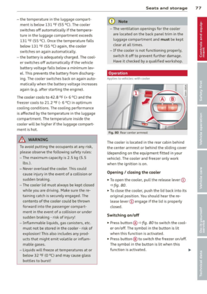
This v iew can ass ist you for examp le, when
you are exiting from an a rea with poor visib ili
ty. The a rea at the front or rea r sides of the
ve hicles is displayed.
.. To see the corner view (front), select the ®
symbol with the control knob
~ fig . 142 .
.. To see the corner view (rear), se lect the ®
symbol wi th the con trol knob~
fig. 143.
Front
Applies to vehicles: with top view camera system and
front mode
Fig. 144 In fo ta inm ent: fr ont mode
P arking systems 129
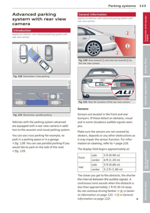
This view assists you for example, in us ing the
full maneuvering range in front of the vehicle.
The area in front of the vehicle is d isplayed .
The vehicle surround ings are shown in the left
area of the display. You can sw itch between
optical display and camera image*
~ page 128 .
.. Select the © symbo l with the control knob.
The orange colored orientation line* de notes the expected d irect ion of travel. Stop
the vehicle at the latest whe n the red orien
tat ion line* bo rders an object
c::> ..&, in Gener
al information on page 127.
, Rear
Applies to vehicles: with top view camera system and rear
mode
Fig . 14 5 Infota inm ent: r ear mod e
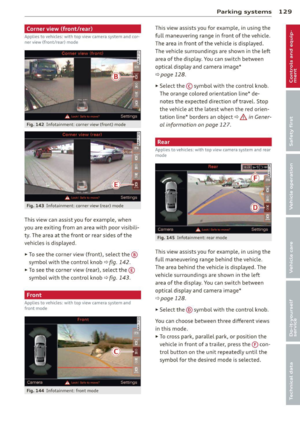
This view assists you for example, in us ing the
full maneuvering range behind the vehicle .
The area be hind the vehicle is displayed . The
vehicle surroundings are shown in the left
area of the display. You can sw itch between
optical display and camera image*
<=> page 128 .
.. Select the @symbo l w ith the control knob.
You can choose between three different v iews
in th is mode .
.. To cross park, para llel park, or pos ition the
veh icle in front of a trailer, press the ® con
trol button on the unit repeatedly unt il the
symbo l for the desired mode is selected.
Page 132 of 314

130 Parking systems
Cross parking
Applies to vehicles: with top vi ew camera system and rear
mode
This view may be used when parking in a ga
rage or in a parking space.
F ig. 146 Infot ainmen t: aim ing at a parking space
Fig. 147 In fo ta inm en t: ali gni ng th e ve hicle
Requirement : cross parking is selected
¢page 129.
.. The orange colored orienta tion lines CD
show t he direction of travel of the vehicle .
Turn the steering whee l until the orange ori
entation lines appear in the parking space
<=> fig . 146. Use the markings @to help you
estimate the distance from an obstacle.
Each marking represents about 3
ft (1 m) .
The blue area represents an extension of the
vehicle 's outline by approximately 16
ft
(5 m) to the rear .
.. While driv in g in reverse gear, adjust the
steering wheel angle to fit the park ing space
with the aid of the o range orientation lines
i::> A in General information on page 12 7,
<=>CD in General information on page 127 .
@ marks the rear bumper. Stop the veh icle
when the red orientation line@ borders an
obstacle
i:> .& in General information on
page 124 .
Parallel parking
Applies to vehicles: with top view camera system and rear
mode
This view may be used when parallel parking
along the side of a street.
Fig . 148 Infota inment : blue s urfa ces aligned in the
par king space
Fig . 149 Infota inmen t: contact of th e bl ue curved line
w ith the curb
Parking on the right is described here. It is
identical when parking on the left.
If there is an obstacle next to the parking
spa ce (such as a wa ll), refer to information for
" Parking next to obstacles "
i::> page 131.
.. Act ivate the turn signal.
.. Posit ion your vehicle next to a parked veh i
cle in front of the desired parki ng space. The
distance to this vehicle should be approxi
mate ly 3 ft (1 m) .
.. Turn the Infota inment on and shift into re
verse gear . The parking system is turned on
and the
parallel parking indicator is dis
played.
.. Press the
CD i:> page 126, fig. 136 control
button on the Infotainment unit repeatedly
until the
cross parking view is displayed .
.. Back up and align your vehicle so the blue
area @ borders on the rear end
of the
Page 133 of 314

vehicle or on the parking space line ¢ & in
General information on page 127,
¢@ in
General information on page 127 .
The blue
area represents an extension of the vehicle's
outline by approx imately 16
ft (5 m) to the
rear . The long side of the blue area should
be o n the curb. The enti re blue area must fit
into the parking space.
~ Wi th the veh icle stopped, turn t he steer ing
whee l to the r ight as far as it w ill go.
~ Back into the park ing space until the b lue
curve¢
page 126, fig . 137 touches the curb
¢ & in General information on page 127,
¢ @ in General information on page 127.
Stop the vehicle.
~ With the vehicle stopped, turn the steering
whee l to the left as far as it will go .
~ Continue to back into the pa rk ing space un
t il the vehicle is par ked pa ra ll el to th e curb
¢ & in General information on page 12 7,
¢(i) in General information on page 127.
@ marks the rear bumper. Stop the veh icle,
at the latest, when the red orientation line
@ borders an object. Keep an eye on the
front of your vehicle wh ile doing this.
Parking n ext to obstacles
When the re is an obs ta cl e (such as a wall)
nex t to the pa rk ing space, choose a space with
more space on the sides. Position the long
side of the b lue area so that there is sufficient
space from the curb. The area must not be on
the curb. You w ill also need to start turning
the steering wheel much earlier . There should
be a suffic ient amount of space between the
curb and the b lue c urve, and the blue curve
¢ page 126, fig. 137 must not touch the cu rb.
@ Tips
The left or right orientation li nes and sur
faces w ill be displayed, depend ing o n the
turn signa l bei ng used.
P arking systems 131
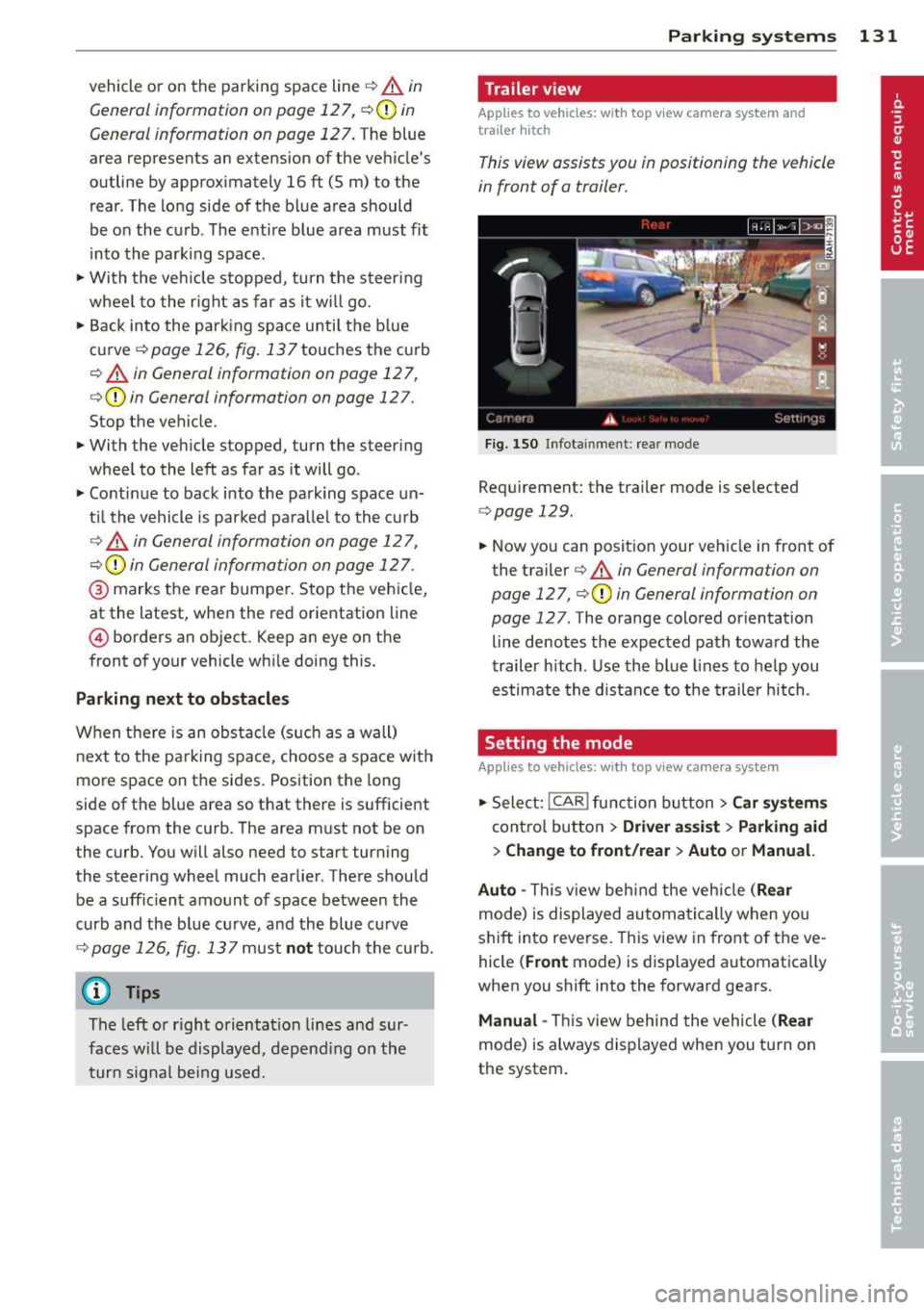
Trailer view
App lies to vehicles: wit h top v iew camera system and
t railer hitch
This view assists you in positioning the vehicle
in front of a trailer.
Fi g. 150 Infotainment: rear mode
Requ irement: the trailer mode is selected
¢page 129.
~ Now yo u can position your veh icle in front of
the trailer ¢
& in General information on
page 127,
¢ (i) in General information on
page 127.
The orange colored orientation
line denotes the expected path towa rd the
trailer hitch . Use the blue lines to help you
es timate the distan ce to the trailer hitch.
Setting the mode
A pp lies to vehicles: wi th top v iew came ra sys te m
~ Select: !CAR ! func tion b utton> C ar system s
contro l butto n > Driver a ssis t > Parking aid
> Change to front /rear > Auto or Manual.
Auto -
This view beh ind the vehicle ( Rear
mode) is displayed au tomatica lly when you
shift into reverse. T his view in front of the ve
hicle
( Front mode) is displayed automatica lly
when you shift into the forward gears.
Manual -This view behind the vehicle (Rear
mode) is always displayed when you turn on
the system .
Page 134 of 314

132 Parking systems
Adjusting the display and the warning tones
App lies to vehicles: with advanced park ing system wit h
rea r view camera/top v iew camera syste m
The display and warning tones can be adjust
ed in the Infotainment.
.. Se lect : ICAR !function button> Car systems
control button > Driver assist> Parking aid.
Display
On* -
optical display is shown for the parking
system plus, rear view camera image is shown
for parking system plus with rear view cam
era*.
Off -when the park ing system is switched off,
on ly audible signa ls are given.
Warning tones
Front volume -
Volume for the fro nt area
Rear volume -Volume for the rear area
Front frequency -Frequency for the front area
Rear frequency -Frequency for the rear area
Music volume while parking -When the park
ing system is turned on, the volume of the au
d io/v ideo source is lowered .
The newly adjusted value is briefly heard from
the signal generator .
(D Tips
-The warning tones can a lso be adjusted
directly from the visual display or the
rear view camera* image . S imply press
the
Settings cont rol button .
- Changed settings are activated when the
parking system is switched on again.
- The settings are automatically stored
and ass igned to the remote control key
that is in use .
Error messages
App lies to vehicles: with advanced park ing system with
rea r view camera/top v iew camera syste m
There is an error in the system if the LED in
the
P •1A b utton is blinking and you hear a con- t
in uous alarm for a few seconds after switch
ing on the parking system or when the park
ing system is already activated. If the error is
not corrected before you switch off the ign i
t ion, the LED in the
P' "A button will blink the
next t ime you sw itch on the parking system by
shifting into reverse .
If a sensor is faulty, the!¾ symbol will appear
in front of/behind the vehicle in the Infota in
ment display . If a rear sensor is faulty, only
obstacles that are in the front detection a rea
are shown . If a front sensor is fau lty, on ly ob
stacles that are in the rear area are shown.
Peripheral cameras*
There is also a system error if:
- the
'(l.Q ,, symbol appears i n the display and
the corresponding display area is shown in
blue. The camera is not work ing in this area.
- all segments around the vehicles are red or
if no segments are displayed.
Drive to your authorized A udi dealer or au
thorized repair facility immediately to have
the malfunction corrected .
Trailer hitch
Applies to vehicles: with adva nced parking sys te m with
rear view camera/top view camera system
For vehicles us ing the trailer socket, the park
ing system rear sensors do not turn on when
yo u shift into reverse gear or when you press
the
P 1JA button. This results in the following re
strictions:
T he re is no distance warning for the rear. The
front sensors remain activated. The visua l dis
play switches to the trailer towing mode . The
rear view camera image will not show the ori
entation lines and the blue surfaces.
(D Tips
Trailer hitches that are not installed at the
factory may ca use the parking system to
malfunction or they may restrict its func
tion.
Page 135 of 314

Homelink
Universal remote
control
General information
Applies to vehicles: with Home link unive rsal remote con
tro l
The Homelink universal remote control can
be programmed with hand -held transmitters
from existing equipment
Using the Homelink universal remote control,
you can operate equ ipment such as garage
doors, property gates and house lights from inside your vehicle .
Using the Homelink universal remote control,
you can replace up to three separate hand
held transmitters for equipment on your
property with just one universal remote con
trol. Most of these transmitters a re used to
operate ga rage doors and property gates. The
individual transmitters are programmed at
the front bumper. That is where the control
module is located.
The transmitters must be programmed first in
order to operate systems using the Homelink
universal remote control.
A WARNING , .,.
- Never use the Homelink transmitter
with any garage door opener that does
have not the safety stop and reverse fea
ture as required by federal safety stand
ards . Th is includes any garage door open
er model manufactured before April 1,
1982.
- A garage door opener which cannot de
tect an object, signaling the door to stop
and reverse does not meet current feder
al safety standards . Us ing a garage door
opener without these features increases
risk of serious injury or death.
- For safety reasons never release the
parking brake or start the engine while
anyone is standing in front of the vehicle .
- A garage door or an estate gate may sometimes be set in motion when the
H ome link 133
Homelink remote control is being pro
grammed. If the device is repeatedly ac
tivated, this can overstrain motor and
damage its electrical components -an
overheated motor is a fire hazard!
- To avoid possible injuries or property
damage, please always make absolutely
certa in that no persons or objects are lo
cated in the range of motion of any
equipment being ope rated.
(D Tips
- If you would like additional information
on the Home link Universal Transce iver
'
Homel ink compatib le products, or to
purchase other accessories such as the
Homelink Lighting Package, please con
tact Homelink at 1-800-355 -3515 or on
the Internet at www. homelink.com.
- For Declaration of Comp liance to United
States FCC and Ind ustry Canada reg ula
tions~
page 295.
Operation
Applies to vehicles: with Homeli nk
Fig. 151 Contro l u ni t in the head liner
"' 8 ±
" m
Requ irement: The buttons must be p rogram
med
~ page 134.
"Press the programmed button~ & in Gen
eral information on page 133
to open the
garage door. The light @will bl ink or turn
on .
" Press the button again to close the garage
door
¢ .&. in General information on
pag e 133 . .,.
Page 136 of 314

134 Homelink
@ Tips
To open t he ga rage door, p ress the butto n,
but do not press it for longer ten seco nds
or the Homelink modu le w ill switch to
programming mode.
Programming transmitters
App lies to vehicles: with Home link
F ig. 152 L eft front area of the bu mpe r
You can prog ram both fixed co de a nd rolling
code systems usi ng these instructions .
Programming a button
> Make sure your ve hicle is wi thin opera ting
r a nge o f th e remo te con trolle d garage door
opener .
> Set the parki ng brake¢ .&. in General infor
mation on page 133.
> Switch the ignition on. Do not s tart the en
gine!
> There are two ways to program a button: press the button that yo u wou ld like to pro
gram . The M MI w ill display i nstruct ions to
guide yo u thr oug h the programm ing. Or
> S e le ct: I CAR I function button> Car system s
control butt on > Vehicle settings > Garage
door opener
> Program garage door open
er .
.. Se lect the b utton t hat you wo uld like to pro
gram.
.. Fo llow the instructions in the MMI.
• If the garage door open ing must a lso be
synchronized wit h the Homelink mod ule,
refer to t he ow ner's manual fo r the ga rage
doo r ope ner.
Erasing the button programming
> Sele ct: I CAR I function butto n > Car sy stems
fu nction key > Vehicle setting s> Garage
door opener
> Clear program settings >
Yes .
Displaying the version/status/country
code
.. Select: I CAR I function button > Car systems
cont ro l button > Vehicle settings > Garage
door opener > Version information .
Programming a button
T he re quired di sta nce between the hand he ld
t ransmit ter and the Homel ink modu le in t he
bumpe r depe nds on the system that you are
programming . When programm ing a new de
vice, keep the b utton pressed for at least 15
seconds before trying aga in with the transm it
te r in a diffe rent position .
Each of the b uttons can be reprogrammed in
dividua lly . The p rocedure is the same as for in
it ial programm ing .
c> page 134 , Programming
a button .
Erasing the button programming
Individual b uttons ca n be re programmed . Fol
l ow the same steps used when first program
ming the button.
If you wo uld like to erase all prog rammed but
tons at the same time, select Erase butto n
programming.
(D Tips
- To ens ure yo ur safe ty, e ras ing t he pr o
gramme d Home link buttons before sell
ing the vehicle is rec ommende d.
- Depending on the model of t he gara ge
door o pener, you may need to release t he
button on the rem ote and press it again
w hen programming .