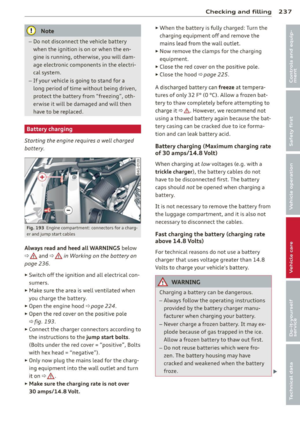
Page 265 of 304

.,. Always store the vehicle tool kit, the jack*
and the replaced tire in the luggage com
partment ¢
page 134.
.,. Unhook the cargo floor before clos ing the
rear lid.
Using the spa re tire (compact spare tir e)
The compact spare tire is on ly intended for
emergencies until you can reach a repair shop .
Replace it as quick ly as poss ible with a stand
ard wheel and tire.
There are some restrictions on the use of the compact spare tire. The compact spare tire
has been designed specifically for your type of
veh icle. It must not be swapped with a com
pact spare t ire from another type of vehicle.
Snow chain s
For technical reasons, the use of snow chains
on the compact spare tire is
not permitted.
If you do have to dr ive w ith snow cha ins and a
front tire f ails, mount the spare whee l with
tire instead of a rear tire . Install the snow
chains on the rear tire and use it to replace
the defective front tire.
A WARNING
-Never use the spare tire if it is damaged
o r if it is worn down to the tread wear in
dicators .
- If the spare tire is more than 6 years o ld,
use it only in an emergency and w ith ex
treme caution and careful driving.
- The spare tire is intended only for tem
porary and short-term use. It should be
replaced as soon as possible w ith the
normal wheel and t ire.
- After mounting the compact spare tire,
the tire pressure must be checked as
soon as poss ible. The tire pressure of the
c ompact spare tire must be 4.2 bar; oth
erwise, you risk hav ing an accident .
- Do not drive faster than 50 mph (80 km/
h). You risk having an acc ident.
- Avoid fu ll-throttle acce le rat ion, heavy
braking, and fast corner ing . You risk hav
ing an acc iden t.
What do I do now? 263
- Never drive using more than one spare
wheel and tire. You r isk having an acci
dent .
- Normal summer or winter t ires must not
be mounted on the compact spare wheel
rim.
- For technical reasons, the use of tire
chains on the spare tire is not permitted .
If it is necessary to drive with t ire chains,
the spare wheel must be mounted on the
front axle in the event of a flat in a rear
tire. The newly available front wheel
m ust then be instal led i n place of the
rear whee l w ith the flat tire. Installing
the tire chain be fore mounting the whee l
and tire is recommended.
- Loose items in the passenger compart
ment can cause serious personal injury
during hard braking or in an accident. Never store the inflatable spare tire or
jack and tools in the passenger compart
ment.
Changing a wheel
Before changing a wheel
Observe the following precautions for your
own and your passenger's safety when chang
ing a wheel.
.,. After you experience a t ire failure, pull the
car well away from mov ing traffic and try to
reach
l e vel ground before you stop ¢ _&.
.,. All passengers should le ave th e car and
move to a safe location (f or instance, behind
the guardrail) ¢
,&.
.. Engage the par king brake to prevent your
veh icle from rolling unintentionally
c:> _&.
.,. Move selecto r le ver to pos it ion P c:> _& .
.,. If you are towing a trailer, unhitch the trailer
from your veh icle.
.,. Take the
ja ck and the s par e tir e out of the
luggage compartment ¢
page 262,
¢page 262. .,.
•
•
Page 266 of 304

264 What do I do now?
&_ WARNING
You or your passengers could be injured
while changing a wheel if yo u do n ot fol
low t hese safety precautions:
- If you have a flat t ire, move a safe dis
tance
off the road. Turn off the engine,
turn the emergency flashers on and use other warning dev ices to alert other mo
torists.
- Make sure that passengers wait in a safe
place away from the vehicle and well
away from the road and traff ic.
- T o help p revent the veh icle from mov ing
sudden ly and possibly slipping off the
ja ck, always fully set the parking b rake
and bloc k the whee l diagona lly opposite
the whee l being changed. When one
front whee l is lifted off the gro und, plac
ing the Automat ic Transmiss ion in P
(Park) will
not prevent the vehicle from
moving.
- Before you change a wheel, be sure the
ground is level and firm. If necessary,
use a sturdy board under the jack.
- Always store the vehicle tool kit, the jack
and the replaced t ire i n the luggage com
partment
c> page 134.
Before chang ing the wheel, yo u m ust acti
vate the jacking mode, so that the auto mat ic cont rols for the Adaptive Air S us
pens ion* do not make it more difficult to
lift the vehicle with the jack
c> page 266.
Changing a wheel
When you change a wheel, follow these
quence described below step-by-step and in
exactly that order .
1. Activate the vehicle jack mode*
~page 266.
-
2. Remove the decorative wheel cov er* . For
mo re details see also
c> page 265, Deco
rative wheel covers
or c> page 265,
Wheels with wheel bolt caps.
3 . L oosen the wheel bolt s c> page 265.
4. Locate the proper mounting point for the
jack and alig n the jack below that point
c> page 266 .
5.
Raise the car with the jack c> page 266.
6. Remove the wheel with the flat tire and
then insta ll
the s pare c>page 267.
7. Tighten all whee l bolts lightly.
8 . Lower the vehicle with the jack .
9. Use the wheel bolt wrench and firmly
t igh ten al l w heel bo lts c> page 265.
10. Replace the decora tive wh eel co ver*.
11. Deactivate the vehicle jack mode * in the
MMI:
I CARI f u nction button > (Car )* sys
tems
control button > Se rvicing & chec ks
> A ir susp .: jac k mode > Off .
The vehicle jack mode * switches off automati
ca lly at speeds above
6 mph (1 0 km/h) .
&_ WARNING ,.__
Always read and follow all WARNINGS and
i nformat ion
c> &. in Raising the vehicle on
page 266
and c> page 268.
After changing a wheel
A wheel change is not complete without the
doing the following.
.,. Always store the vehicle tool kit, the jack*
and the rep laced tire in the luggage com
partment
c> page 134.
.,. Check the tire pressu re on the spare whee l
immed iate ly after mounting it .
.,. As soon as poss ible, have the
tight ening
torques
on all whee l bolts checked with a
t o rque wrenc h. The co rrect tighte ning tor
que is 90 ft lb (120 Nm).
.,. Have the fla t tire
replaced as soon as possi
b le.
(D Tips
- If you not ice th at the wheel bo lts a re
co rroded and difficult to turn while
changing a tire, they should be rep laced
before you check the tightening torque.
- Drive at reduced speed until you have the
tightening torques checked .
ll-
Page 267 of 304

-After changing a wheel, the tire pressure
in all four tires must be checked/correct
ed and the tire pressure mon itor ing indi
cator must be stored in the MMI
qpage260 .
Decorative wheel covers
Applies to vehicles: with decorat ive wheel covers
The decorative wheel covers must be removed
first to access the wheel bolts.
Fig. 206 Changing a wheel: Removing the wheel cover
Removing
.,.. Insert the hook (provided with the veh icle
tool kit) in the hole in the wheel hub cover .
.,.. Pull off the
decorative wheel cover
qfig. 206.
Wheels with wheel bolt caps
Applies to vehicles: with wheel bo lts w it h caps
The caps must be removed first from the
wheel bolts before the bolts can be un
screwed.
Fig . 207 Changing a whee l: remov ing t he wheel bolt
caps
Removing
.,.. Push the plastic clip (provided with the vehi
cle tool kit) over the wheel bolt cap until the
What do I do now? 265
inner retainers on the clip align with the
edge of the cover .
.,.. Remove the cap with the
plastic clip (veh icle
tool kit)
qfig . 207.
Refitting
.,.. Place the caps over the whee l bolts and
push them back on .
The caps are to protect and keep the wheel
bo lts clean.
loosening and tightening the wheel
bolts
The wheel bolts must be loosened before rais
ing the vehicle.
Fig . 208 Changing a wheel: l oosen ing th e whee l bo lts
loosening
.,.. Slide the wheel wrench onto the wheel bo lt
as far as it will go.
.,.. Take tight hold of the
end of the wrench
handle and turn the wheel bolts
counter
clockwise
about one single turn in the direc
tion of arrow
q fig . 208.
Tightening
.,.. Slide the wheel wrench onto the wheel bolt
as far as it w ill go .
.,.. Take tight hold of the
end of the wrench
handle and turn each wheel bolt
clockwise
until it is seated.
_&. WARNING
- Do not use force or hurry when chang ing
a wheel -you can cause the vehicle to slip
off the jack and cause serious personal injuries.
Page 268 of 304

266 What do I do n ow ?
-Do not loosen the wheel bolts more than
one turn
before you raise the veh icle with
the jack. -You risk an injury .
@ Tips
-Never use the hexagonal socket in the
handle of the screwdriver to loosen or
tighten the wheel bo lts.
- If a whee l bolt is very tight, you may find
it easier to loosen by carefully pushing
down on the end of the wheel bolt
wrench w ith
one foot only. As you do so,
hold on to the car to keep your balance
and take care not to slip .
Raising the vehicle
The vehicle must be li~ed with the jack first
before the wheel can be removed .
Fig. 209 Sill pa nels : m ark ings
~
9
---;~ :~-;;:--~
Fi g. 210 Sill : pos ition ing the ve hicle jack
., Activate the vehicle jack mode* in the M MI:
I CAR ! func tion button > (C ar )* sys te m s con
t ro l butto n
> Servici ng & che cks> Air su sp. :
j ack mode > On .
.. Engage the par king br ake to prevent your
vehicle from ro lling unintentionally.
., Move the
selector le ver to posit ion P.
.. Find the marking (imprint) on the sill that is
nearest the whee l that will be changed
¢
fig. 209. Be hind the marking, there is a
lift ing point on the sill for the vehicle jack .
., Vehicles with a sill: remove the cover from
the sill before lift ing the veh icle w ith a vehi
cle jack ¢
page 267.
., Turn the vehicl e jack located under the lift
ing point on the sill to ra ise the jack u nti l its
arm
@ ¢fig. 210 is located under the des
ignated p lastic mount ¢ _&. ¢(D.
.. Align the jack so that its
arm @¢fig . 210
engages in the designated lifting point in
the door si ll and the movable base @ lies
flat on the ground. The base ® must be
ver
t ical
under the lifting point @ .
., Wind the jack up further until the flat t ire
comes off the ground ¢
,&..
Position t he veh icle jack onl y under the desig
nated lifting points on the s ill ¢
fig . 209 .
T here is exactly
one locat ion for each wheel.
T he jack must not be positioned at any other
location ¢ _& ¢(j) .
An
un stab le surfa ce under the jack can cause
the vehicle to slip off the jack . Always provide
a firm base for the jack on the ground .
If nec
essary place a sturdy board or sim ilar support
u nder the jack. On
h ard , s lipp ery surf aces
(such as tiles) use a rubber mat or similar to
preve nt the jack from slipping ¢
.&..
A WARNING
--You or your passengers co uld be injured
while changing a wheel if you do not fo l
low these safety precautions:
- Position the vehicle jack on ly at the
designated lifting poi nts and align the
jac k. Otherw ise, the vehicle ja ck could
slip and cause an injury if it does not
have sufficient hold on the vehicle.
- A soft or uns table su rface under the
j ack may cause the vehicle to slip off
the jack . Always provide a firm base for
the jack on the ground. If necessary,
use a sturdy board under the jack. ,..
Page 269 of 304

-On hard, slippery surface (such as tiles)
use a rubber mat or similar to prevent
the jack from slipping .
- To help prevent injury to yourself and
your passengers:
- Do not raise the vehicle until you are
sure the jack is securely engaged.
- Passengers must not remain in the ve
hicle when it is jacked up.
- Make sure that passengers wait in a
safe place away from the vehicle and
well away from the road and traffic.
- Make sure jack position is correct , ad
just as necessary and then continue to
raise the jack.
- Changes in temperature or load can af
fect the height of the vehicle.
(D Note
Do not lift the vehicle by the sill. Position
the vehicle jack only at the designated lift
ing points on the sill. Otherwise, your vehi
cle will be damaged.
(D Tips
The vehicle jack mode* switches off auto
matically at speeds above 6 mph (10 km/
h).
Removing and installing the sill cover
Applies to vehicles : wit h sill
Fig. 211 Sill: remov ing t he cover
.,. Pull the cover down to remove it c'> fig. 211.
.,. To install the cover again, insert it into the
retainers and then swing it upward until it
clicks into place. The cover must be flush
with the sill.
What do I do now? 267
@ Tips
Some models may also have a cover for the
rear vehicle lift point.
Taking the wheel off/installing the spare
Follow these instructions step-by-step for
changing the wheel.
Fig. 212 Changing a wheel: using the screwdrive r han
dle (w it h th e blade re m oved) to turn the bolt s
Fig. 213 Changing a wheel : alignment p in in sid e the
top hole
After you have loosened all wheel bolts and
raised the vehicle
off the ground, remove and
replace the wheel as follows :
Removing the wheel
.,. Use the hexagonal socket in the screwdriv
er handle
to completely remove the top
most wheel bolt and set it aside on a clean
surface c>fig. 212 .
.,. Screw the threaded end of the
alignment
pin
from the tool kit hand-tight into the
empty bolt hole r::;;fig . 213 .
.,. Then remove the other wheel bolts as de
scribed above .
.,. Take
off the wheel leaving the alignment pin
in the bolt hole
r::;; d). ..,.
Page 270 of 304

268 What do I do no w?
P uttin g on the spare wheel
.. Lift the spare wheel and ca refully slide it
over the alignment pin to guide it in place
¢ (D .
.. Use the hexagonal socket in the screwdriver
handle to screw in and tighten all wheel
bolts
slightly.
.. Remove the alignment pin and insert and
t ighten the remaining wheel bolt slightly
l ike the rest .
.. Turn the jack handle counte r-clockw ise to
lower the vehicle unt il the jac k is fully re
leased.
.. Use the wheel bolt wrench to tighten all
wheel bolts firmly¢
page 265 . Tighten
them
crosswise, from one bolt to the (ap
proximately) opposite one, to keep the
wheel centered.
When removing or installing the wheel,
the rim could hit the brake rotor and dam
age the rotor. Work carefully and have a
second person help you .
(j) Tips
Never use the hexagonal socket in the han
dle of the screwdriver to loosen or t ighten
the wheel bolts .
- Pull the reversible blade from the screw
driver before you use the hexagonal
socket in the handle to turn the wheel bo lts.
- When mounting tires with
unid ir ec tional
tread design
make su re the tread pat
tern is pointed the right way
¢ page 268.
-The wheel bolts should be clean and easy
to tu rn . Check for d irt and corrosion on
t h e mat ing s urfaces of both the whee l
and the h ub. Remove al l dirt from these
s ur faces before remo unting the wheel.
Tires with unidirectional tread design
Tires with unidirectional tread design must be
mounted with their tread pattern pointed in the right direction .
Using a sp are t ire w ith a tre ad pattern
intended for use in a specific direction
When using a spare t ire with a tread patter n
intended for use in a spec ific d irection , please
note the following :
- The direct ion of rotation is marked by an ar
row on the side of the ti re .
- If the spare tire has to be installed in the in
correct direct ion, use the spare tire only
temporarily s ince the tire will not be able to
achieve its optim um performance cha racte r
is tic s wit h regard to aquap la ni ng, no ise and
wear .
- We recommend that you pay part icu la r at
t en tion to th is fact d uring wet wea ther and
t ha t you adjust you r speed to match road
conditions .
- Replace the fl at tir e with a new o ne an d
have it insta lled on you r vehicle as soon as
possible to resto re the handling advantages
of a u nidirectional tire .
Notes on wheel changing
Please read the information¢ page 251, New
tires and replacing tires and wheels
if you a re
going to use a spare tire which is different
from the ti res on your vehicle .
After you change a tire:
- Check the tire pre ssure on the spare imme
diately after install ation.
- Have th e whe el bolt tightening torque
c hecked with a torque wrench as soon a s
possible by your author ized Audi dealer or
a qualified service stat ion.
- With steel and alloy wheel rims, the wheel
bolt s are cor re ctl y tightened at a torque of
90 ft lb (120 Nm ).
- If you noti ce that the wheel bolts are cor
roded and diffi cult to turn while changing
a ti re , they should be replaced before you
check the t ightening torque. .,..
Page 271 of 304
-Replace the flat tire with a new one and
have it installed on your vehicle a s soon as
possible. Remount the wheel co ve r.
U ntil th en, driv e with extr a car e and at re
du ced speeds .
~ WARNING
-
-If you are going to equip your vehicle
with t ires or rims wh ich differ from those
wh ich were factory installed, then be
sure to read the informat ion
c:> page 251,
New tires and replacing tires and
wheels.
- Always make sure the damaged wheel or
even a flat tire and the jack and tool k it
are properly secured in th e luggage com·
partment and are not loose in the pas·
senger compartment.
- In an accident o r sudden maneuver they
c ou ld fly forward, inju ring anyone in the
vehicle .
- Always store damaged w heel, jac k and
tools secure ly in the luggage compart
ment. Otherw ise, in an acc iden t or sud
den maneuver they cou ld fly forward,
causing injury to passenge rs i n the vehi·
cle .
What do I do now? 269
•
•
Page 272 of 304

2 70 Fuses and bulbs
Fuses and bulbs
Fuses
Replacing fuses
Fuses that have blown will have metal strips
that have burned through.
Fig. 214 Dr iver side of the cockpit: fuse panel cover
The fuses are located at the front left and
right of the cockpit and behi nd the trim on
the right side of the luggage compartment.
• Switch the ign ition and the affected electri
c al equ ipment off.
• Check the following table to see which fuse
belongs to the consumer.
• Remove the cover ¢
fig. 214 or¢ page 220,
Opening the side trim.
• To remove the purple plast ic clip if necessa
ry
ll, hold onto it at the small side and pull
i t out of the fuse panel
c:> page 2 70,
fig. 215 .
• Remove the clamp from the rear s ide of the
fuse cover ¢
fig. 214.
• Remove the fuse using the cla mp and re
pla ce the blown fuse w ith an ident ical new
one.
A WARNING
Do not repair fuses and never rep lace a
blown fuse with one that has a higher amp
rating. This can cause damage to the e lec
trical system and a fi re.
ll You can dis pose of the plastic clip after removing it.
(D Note
If a new fuse burns out again after shortly
have you have installed it, have the electri
ca l system checked by yo ur authorized
Audi dealer.
(D Tips
- The following table does not list fuse lo
cations that are not used .
- Some of the equipment items listed are
optional or only available on certain
model configurations.
Driver side cockpit fuse assignment
Fig . 2 15 Dr iver side cockpit: fuse pa nel w ith plast ic
bracket
Fuse panel ® (blac k)
No. Equipment Amps
Switch panel, electromechan ica l
1 parking brake, seat heating, 5
starting assist, control module
2 Automatic d imming in terior
5 rea rview mirro r, horn
3 Exhaust system (diesel engine) 10