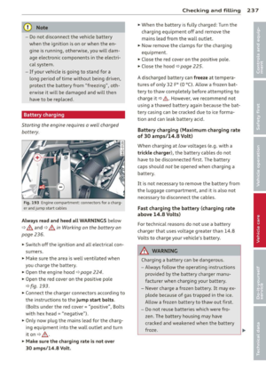
Page 121 of 304

r::> & in General information on page 116,
r::>(D in General information on page 117.
The blue area represents an extens ion of the
vehicle's outline by approximately 16 ft
(5 m) to the rear . The long side of the blue
area should be on the curb . The entire blue
area must fit into the parking space.
• With the veh icle stopped, turn the steering
wheel to the right as far as it w ill go.
• Back in to the park ing space u ntil the b lue
curve
r::> fig . 128 touches the curb r::> & in
General information on page 116,
r::> (D in
General information on page 117 .
Stop the
vehicle.
• With the veh icle stopped , turn the steer ing
whee l to the left as far as it will go .
• Continue to back into the parking space un
t il the vehicle is parked pa rallel to the cu rb
r::> & in General information on page 116,
r::> (D in General information on page 117.
@ marks the rear bumper . Stop the veh icle,
at the latest, when the red orientation line
@ borders an object. Keep an eye on the
front of your vehicle whi le do ing th is .
Pa rking next to obstacles
If there is an obstacle (s uc h a s a wall) next to
the par king space, position the veh icle so
there is more space o n that s ide. Position the
l ong side of the blue s urface so that there is
sufficient space from the obstacle . The sur
face must not be to uch ing . You will also need
to star t turning the steer ing wheel much ear
lier . The blue curve
r::> fig . 128 must not touch
the obstacle and should have sufficient room.
(D Note
Remember to maintain sufficient clear
ance from the curb to avoid damag ing the
wheel rims .
(D Tips
The left or right orientation lines and sur
faces will be displayed, depend ing on the
turn sig na l being used.
P arking systems 119
Peripheral cameras
Introduction
Applies to vehicles: with parking system plus with periph
eral cameras
In add ition to parking system plus
¢
page 115, this parking system conta ins pe
ripheral cameras . Depending on the vehicle
equipment , you are ass isted by vario us views
su ch a s p eriphera l view, corne r views a t the
fron t and rear of the veh icle, and views di rect
ly in front of or behind t he vehicle .
General information
Applies to vehicles: with parking system plus with periph
eral cameras
F ig . 12 9 Locat io n of per ip hera l ca meras
Depending on the vehicle equipment, the pe
ripheral cameras are found in the radiator
grille, in the luggage compartment lid and on
both exterior mirrors* ¢
fig. 129 . Make su re
that the lenses a re not covered by depos its o r
any other obstr uctions as it may impa ir t he
system. For info rmat io n on clean ing, refe r to
¢ page 210.
In the peripheral mode , b lack corners are
shown in the ve hicle silhouette . Objects in
these a reas a re outside of the came ra's field
of view and are not detec ted .
The accuracy of the orientation lines and the
bl ue surfaces is reduced if the adaptive a ir
suspension* is faulty, if the vehicle is l ifted or
if t he
D ynamic mode is activa ted ¢ page 100 . ..,.
Page 122 of 304

120 Park in g s ystems
& WARNING
- Always read and follow the applicable
warnings
Q .&. in General information on
page
114.
- If the posit ion or the installation angle
of a camera was changed, after a colli
sion for example, do not continue to use
the system for safety reasons. Have it
checked by your authorized Audi dealer
ship.
- Keep in m ind that the image i n the dis
play is distorted if the ex ter ior mirro r
housing has been man ual ly adjusted.
- Use the
re ar mode and the corner vi ew
(re ar)
mode on ly when the luggage com
partment lid is fully closed. Otherwise
the image in the display will be distort
ed.
- The veh icle surroundings are shown us
ing the camera images. The vehicle im
age is shown by the system. Objects and
obstacles above the camera are not dis
played.
- Camera lenses en large and distort the
field of v is ion. The objects appear both
altered and inaccurate on the screen.
(D Note
-Always read and follow the applicab le
warnings
c:> (i) in General information on
page
114.
- The Infota inment display shows the di
rection in which the rear of the vehicle is
traveling based on the steering wheel
angle . The front of the veh icle front
swings out more than the rear of t he ve
hicle. Ma intain plenty of distance so that
you r outside m irror or a corner of you r
vehicle does not coll ide wi th any obsta
cles.
@ Tips
I f the 8/cr;iJ/r:;::::s symbol appea rs i n the
disp lay and the respec tive display area is
grayed out, then the power exter io r mir
rors were fo lded in or the driver's door/ front passenger's door/
luggage compart
ment lid was opened.
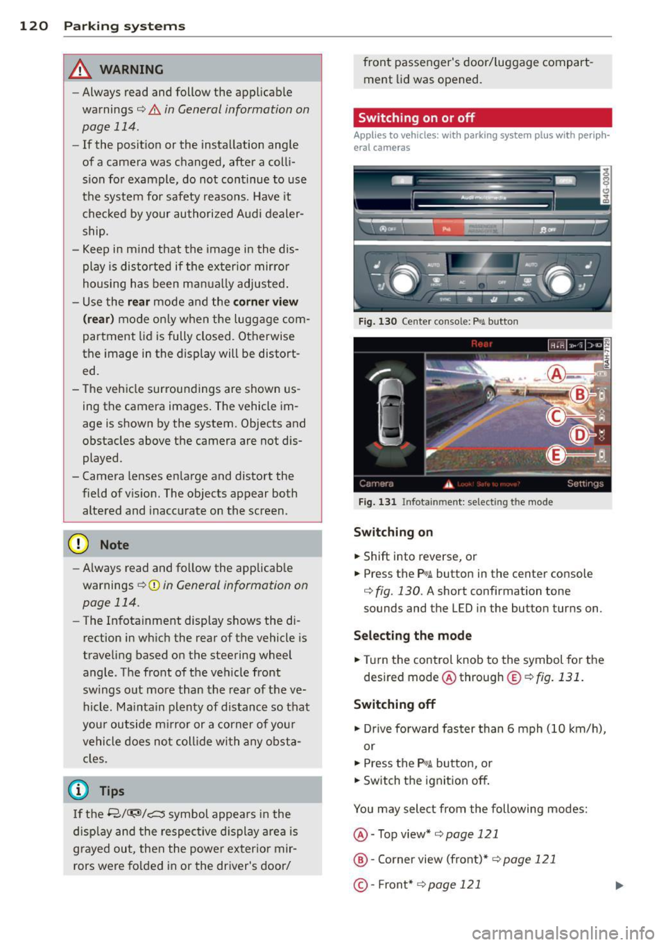
Switching on or off
Applies to vehicles: with parking system plus with periph
eral cameras
Fig . 1 30 Ce nte r console: f>• JI butto n
Fig . 1 31 Infota inment: selecting t he mode
Sw itching on
.. Shift into reverse, or
.. Press the P•QJ\. button in the center console
c:> fig. 130 . A short confirmation tone
sounds and the
LED in the button turns on.
Selecting the mode
.. Turn the control knob to the symbol fo r the
desired mode @ through @¢
fig. 131 .
Switching off
.. Dr ive fo rward faster than 6 mph (10 km/ h),
or
.. Press the
P"li bu tton, or
.. Switch the ignition off .
You may sele ct from the following modes:
@ -Top view*
c:>page 121
@ -Corner view (front)* c:> page 121
©-Front * c:> page 121
Page 123 of 304

@-Rear* ¢ page 122
©- Corner view (rear)* ¢ page 121
Top view
Applies to vehicles: with parking system plus and top view
mode
Fi g. 1 32 In fota inm ent: top v iew mode
This v iew is ideal for maneuve ring. The vehicle
surro undings are shown using the camera im
ag es. The vehicle image is shown by the sys
tem.
Selecting top vi ew
~ Se lect the @symbol with the control knob.
Switching between optical view and
came ra image
1
)
~ To d isp lay the camera image, press the c am
era
contro l bu tton @ .
~ Press the Graph ic control button to see the
opt ica l display .
Corner view (front /rear )
Applies to vehicles: with parki ng system plus and corner
view (front/rear ) mode
Fig. 133 In fot ainm en t: co rn er view (fro nt} mode
1 1
Th e cam era im age is n ot s how n for al l ve rs ion s.
Parking systems 121
Fig . 1 34 Infot ainm en t: corne r vie w (r ea r) mode
This view can assist you for example, when
you are exit ing from an area with poor visibili
ty . The area at the front or rear sides of the
vehicles is displayed .
~ To see the corner view (fron t), select the @
symbol with the control knob
¢ fig . 133 .
~ To see the co rner v iew ( rear), select the ©
symbo l with the control knob
r=> fig . 134 .
, Front
Applies to vehicles: with parking system plus and front
mo de
Fig. 1 35 ln fota inment: front mode
T his view assis ts you for example, in us ing the
full maneuver ing range in front of the vehicle.
The area in front of the vehicle is displayed .
The vehicle s urround ings are shown in the left
area of the display . You can switch between
optical display and camera image*
<=> page 121.
~ Select the © symbo l with the control knob .
T he o range colored orientation line* de
notes the expected d irection of travel. Stop
the vehicle at the latest when the red
Iii>-
Page 124 of 304

122 Park in g s ystems
orientation line * borders an object q .&. in
General information on page 120 .
Rear
Applies to vehicles: with parking system plus and rear
mode
F ig. 136 Infotainment: rear mode
This view assists you for example, in using the
full maneuvering range behind the veh icle.
The area beh ind the veh icle is d isplayed. The
vehicle surroundings are shown in the left
area of the display. You can switch between
optical d isplay and camera image*
¢page 121 .
.,. Select the @symbol with the control knob.
You can choose between three different views in this mode.
.,. To cross park, parallel park, or position the
vehicle in front of a tra iler, p ress the ® con
t ro l button on the un it repeatedly until the
symbol for the des ired mode is se lected.
Cross parking
Applies to vehicles: w ith park ing system plus and rear
mode
This view may be used when parking in a ga
rage or in a parking space.
F ig . 1 37 Infotainment: aiming at a pa rki ng space
Fig . 1 38 Infotainment: aligning the vehicle
Requirement: cross parking is se lected
Q page 122 .
.,. The orange colored orientation lines@
show the direction of travel of the vehicle.
T urn the steering wheel until the orange ori
entation lines appear in the parking space
¢ fig. 137 . Use the mark ings @to he lp you
estimate the distance from an obstacle.
Each marking represents about 3 ft (1 m).
The b lue area represents an extension of the
veh icle's outline by approximate ly 16 ft
(5 m) to the rear .
.,. Wh ile d riving in reverse gear, adjust the
steer ing whee l ang le to fit t he parking space
w ith the aid of the orange or ientat ion lines
¢ .&. in General information on page 120,
¢ (Din General information on page 120.
® marks the rear bumper. Stop the vehicle
when the red orientation line© borders an
obstacle
¢ .&. in General information on
page 116.
Page 125 of 304

Parallel parking
Applies to vehicles: with parking system plus and rear
mode
This view may be used when parallel parking
along the side of a street.
F ig. 139 Infot ainme nt: bl ue su rfaces aligned in th e
park ing space
Fig . 14 0 Infota inmen t: co ntact of the blue curved line
with t he curb
Parking on the right is described he re. It is
ident ical when parki ng on the left .
I f there is an obstacle next to the park ing
space (such as a wall), refer to information for
"Parking nex t to obstacles"
c::> page 123.
~ Activate the turn s ignal.
~ Position your vehicle next to a parked vehi
cle in front of the desired parking space . T he
distance to th is vehicle sho uld be approxi
mately 3 ft (1 m).
~ Turn the Infotainment on and shift into re
verse gear. The parking system is turned on
and the
parallel parking i ndicator is dis
played .
~ Press the@¢ page 118 , fig . 127 control
button on the Infotainment un it repeatedly
unt il the
cross parking view is disp layed.
~ Backup and align yo ur vehicle so the blue
area @ borders on the rear end of the vehi-
Parking systems 123
cle or on the parking space line c::> A in Gen
eral information on page 120,
c::> (D in Gen
eral information on page 120.
The b lue area
represent s an extens ion of the vehicle 's out
line by approximately 16 ft (5 m) to the rear.
The long side of the blue area should be on
the curb . The entire blue area must fit into
th e parking space .
~ With the vehicle stopped, turn the stee ring
wheel to t he righ t as fa r as it will go.
~ Back into the parking space unt il the blue
curve
c::> page 118, fig. 128 to uches the curb
c::> A in General information on page 120,
c::> (D in General information on page 120.
Stop the vehicle.
~ With the vehicle s topped, turn the steering
wheel to the left as far as it w ill go.
~ Continue to back into the parking space un
til the vehicle is parked parallel to the curb
c::> ..&. in General information on page 120,
c::> (D in General information on page 120.
@ marks the rear bumper. Stop the vehicle,
at the latest, when the red orientation line
@ borders an object . Keep an eye on the
front of your vehicle while do ing this .
Parking next to obstacles
When there is an obstacle (such as a w all)
next to the parking space, choose a space with
more space on the sides . Positio n the long
side of the blue area so that there is suff icient
space from the curb. The area must not be on
the curb. You will a lso need to start turning
the steering wheel much earlier . T here should
be a sufficient amount of space between the
c ur b and the bl ue curve, and t he b lue curve
c::> page 118, fig . 128 m ust no t touch the curb.
@ Tips
The left o r right orientation lines and su r
faces w ill be disp layed, depending on the
turn s ignal being used .
Page 126 of 304

124 Park in g s yste m s
Trailer view
Applies to vehicles: with par king system p lus and tra iler
hitch
This view assists you in positioning the vehicle
in front of a trailer.
F ig. 1 41 Infotainment: rear mode
Requirement: the trailer mode is selected
c:;,page 122.
.. Now you can pos ition your vehicle in front of
the trailer
c:;, A in General information on
page 120,
c:;, (D in General information on
page 120.
The orange colored orientation
line denotes the expected path toward the
trailer hitch . Use the b lue lines to he lp you
est imate the d istance to the t railer hi tch.
Setting the mode
A ppl ies to vehicles: with park ing system wit h peripheral
cameras
.. Se lect : I CAR I func tion button> (Car )* sys
t e m s
control button > Dri ver as sis t > Park
ing aid > Ch ange to front /re ar > Aut o
or
Manua l.
A uto -
Th is view behind the vehicle ( Rea r
mode) is d isplayed automatically when you
shift into reverse. This view in front of the ve
h icle
( Fron t mode) is d isp layed automatically
when you sh ift into the fo rward gears .
Manual -This view behind t he vehicle (Rear
mode) is a lways d is p layed when you turn on
the system .
Adjusting the display
and the warning tones
Applies to vehicles: wit h parking system plus/ rea r vi ew
came ra/ peri pheral cameras
The display and warning tones can be adjust
ed in the Infotainment.
.. Select: !CARI function button > ( Car )* sys
tem s
control button > Drive r a ssist > Par k
in g a id .
Di splay
On * -
optical display is shown for the parking
system p lus, rear view camera image is shown
for parking system plus with rear view cam
era*.
Off -when the parking system is switched off,
only audible signals are given .
Warning tones
Fr ont volume -
Volume for the front area
Rear volume -Volume for the rear area
Front frequency -Frequency for the front area
Rear frequen cy -Frequency for the rear area
Mu sic v olum e wh ile parkin g -When the park
ing system is turned on, the volume of the au
dio/video sou rce is lowered.
The newly adjusted value is briefly heard from
the signal generator .
@ Tips
-The warn ing tones can also be adjusted
directly from the visual display o r the
rear v iew camera* image. Simply press
the
Setting s control button .
- Changed settings are act ivated when the
park ing system is switched on again.
- The settings are automatica lly stored
and assigned to the remote control key
that is in use .
Page 127 of 304

Error messages
Applies to vehicles: with parking system plus/rear view
camera/per ipheral cameras
There is an e rror in the system if the LED in
the
p, qA button is blinking and you hear a con
tinuous alarm for a few seconds afte r switch
ing on the parking system or when the park
ing system is already activated. If the error is
not corrected before you switch off the igni
tion, the LED in the
Pw.6. button will blink the
next time you switch on the parking system by
shifting into reverse.
Parking system plus
If a sensor is faulty, the~ symbol will appear
in front of/behind the vehicle in the Infotain
ment display. If a rear sensor is fau lty, only
obstacles that are in areas @ and @ are
shown ¢
page 115, fig. 118. If a front sensor
i s faulty, only obstacles that are in areas ©
and @are shown .
Peripheral cameras*
There is also a system error if:
- the
'(:8:)• • symbol appears in the display and
the corresponding display area is shown in
blue. The camera is not working in this area.
- all segments around the vehicles are red or
if no segments are displayed.
Drive to your authorized Aud i dea ler o r au
thorized repair fac ility immediately to have
the ma lfunction corrected.
Trailer hitch
Appl ies to vehicles: with parking system plus/rear view
camera/per ipheral cameras and trailer hitch
For vehicles using the tra iler socket, the park
ing system rear senso rs do not turn on when
you shift into reverse gear or when yo u press
the P
01A button. This results in the following re
strictions:
Parking system plus*
There is no distance wa rning for the rear. The
front sensors rema in activated. The visual dis
play switches to the traile r tow ing mode.
Parking systems 125
Parking system plus and rear view
camera* /Peripheral cameras*
There is no distance warning for the rear. The
front sensors remain activated. The visual dis
play sw itches to the trailer towing mode. The
rear view camera image will not show the ori
entation lines and the blue surfaces .
{D Tips
Trailer hitches that are not installed at the
factory may cause the park ing system to
malfunction or they may restr ict its func
tion.
Page 128 of 304

126 Homelink
Homelink
Universal remote
control
General information
Applies to vehicles: with Homelink u nive rsal remote con
tro l
The HomeLink universal remote control can
be programmed with hand-held transmitters
from existing equipment.
With Homelink, you can control devices such
as the garage door, security systems, house
lights, etc. comfortably from the inside of you
vehicle.
Homelink makes it possible for you to replace
three different remote controls from devices in your home with one universal remote . Th is
feature works for most garage door and exte
rior door motor signals. Programming the in
d iv idual remo te control fo r your remote con
trol takes p lace near the center of the radiator
grille. There is a control module attached at
this location .
A one-t ime programm ing of the sensor mus t
be performed before you are able to use sys
tems w ith Homelink.
A WARNING
- Never use the Homelink transmitter
with any garage door opener that does
have not the safety stop and reverse fea
ture as requ ired by federal safety stand
ards. Th is includes any garage door open
er model manufactured before April 1, 1982.
- A garage door opener which cannot de
tect an object, signaling the door to stop
and reverse does not meet current feder
al safety standards . Us ing a garage doo r
opener witho ut these fea tures increases
risk of serious injury or death.
- For safety reasons never release the
parking brake or start the engine while
anyone is standing in front of the vehicle .
- A garage door or an estate gate may
sometimes be set in motion when the Homelink remote control is being pro
grammed. If the device is repeatedly ac
tivated, this can overstrain motor and
damage its electrical components -an
overheated motor is a fire hazard!
- To avo id possible injuries or property
damage, please always make absolutely
certa in that no persons or objects are lo
cated in the range of motion of any
equ ipment being operated.
(0 Tips
- If you would like additional information
on the Homelink Un iversal Transceiver,
Homelink compatible products, or to
purchase other accessories su ch as the
Homelink Lighting Package, please con
tact Homelink at 1 -800-355-3515 or on
the Internet at www.homelink.com.
- For Declara tion of Comp liance to United
States FCC and Ind ustry Canada reg ula
tions¢
page 286 .
-For security reasons, we recommend that
you clear the programmed b uttons be
fore selling the ve hicle .
Operation
Appl ies to vehicles: wit h Ho melink
Fig . 14 2 Headliner: controls
M 0
9 (!)
~
Requirement: The buttons must be program
med
¢page 127.
"'To open the garage door , press the program
med b utton . The LED @ will light up o r
flash.
"' To close the garage door, press the button
again .
Ill>