Page 41 of 100

INSTRUMENT AND CONTROL FUNCTIONS
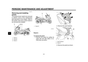
3-26
234
5
6
7
8
9
EAU46021
Shock absorber assembly
WARNING
EWA10221
This shock absorber assembly con-
tains highly pressurized nitrogen
gas. Read and understand the fol-
lowing information before handling
the shock absorber assembly.
Do not tamper with or attempt to
open the cylinder assembly.
Do not subject the shock ab-
sorber assembly to an open
flame or other high heat source.
This may cause the unit to ex-
plode due to excessive gas
pressure.
Do not deform or damage the
cylinder in any way. Cylinder
damage will result in poor
damping performance.
Do not dispose of a damaged or
worn-out shock absorber as-
sembly yourself. Take the shock
absorber assembly to a Yamahadealer for any service.
EAU15305
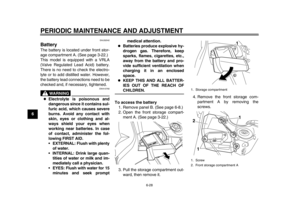
Sidestand The sidestand is located on the left side
of the frame. Raise the sidestand or
lower it with your foot while holding the
vehicle upright.TIPThe built-in sidestand switch is part of
the ignition circuit cut-off system, which
cuts the ignition in certain situations.
(See the following section for an expla-
nation of the ignition circuit cut-off sys-tem.)
WARNING
EWA10241
The vehicle must not be ridden with
the sidestand down, or if the side-
stand cannot be properly moved up
(or does not stay up), otherwise the
sidestand could contact the ground
and distract the operator, resulting
in a possible loss of control.
Yamaha’s ignition circuit cut-off
system has been designed to assist
the operator in fulfilling the respon-
sibility of raising the sidestand be-
fore starting off. Therefore, check
this system regularly and have aYamaha dealer repair it if it does not
function properly.
59C-9-E1.book 26 ページ 2012年6月26日 火曜日 午前11時33分
Page 42 of 100
INSTRUMENT AND CONTROL FUNCTIONS
3-27
1
23
4
5
6
7
8
9
EAU45052
Ignition circuit cut-off system The ignition circuit cut-off system (com-
prising the sidestand switch and brake
light switches) has the following func-
tions.
It prevents starting when the side-
stand is up, but neither brake is ap-
plied.
It prevents starting when either
brake is applied, but the sidestand
is still down.
It cuts the running engine when the
sidestand is moved down.
Periodically check the operation of the
ignition circuit cut-off system according
to the following procedure.
59C-9-E1.book 27 ページ 2012年6月26日 火曜日 午前11時33分
Page 43 of 100

INSTRUMENT AND CONTROL FUNCTIONS
3-28
234
5
6
7
8
9
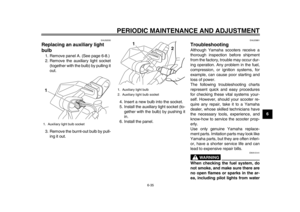
With the engine turned off:
1. Move the sidestand down.
2. Make sure that the engine stop switch is turned on.
3. Turn the key on.
4. Keep the front or rear brake applied.
5. Push the start switch.
Does the engine start?
With the engine still off:
6. Move the sidestand up.
7. Keep the front or rear brake applied.
8. Push the start switch.
Does the engine start?
With the engine still running:
9. Move the sidestand down.
Does the engine stall?
The system is OK. The scooter can be ridden.The sidestand switch may not be working correctly.
The scooter should not be ridden until
checked by a Yamaha dealer.
The sidestand switch may not be working correctly.
The scooter should not be ridden until
checked by a Yamaha dealer.
YES NO YES NO NO YES
The brake switch may not be working correctly.
The scooter should not be ridden until
checked by a Yamaha dealer.• The vehicle must be placed on the center-
stand during this inspection.• If a malfunction is noted, have a Yamaha
dealer check the system before riding.
WARNING
59C-9-E1.book 28 ページ 2012年6月26日 火曜日 午前11時33分
Page 44 of 100

4-1
1
2
34
5
6
7
8
9
FOR YOUR SAFETY – PRE-OPERATION CHECKS
EAU15596
Inspect your vehicle each time you use it to make sure the vehicle is in safe operating condition. Always follow the inspection
and maintenance procedures and schedules described in the Owner’s Manual.
WARNING
EWA11151
Failure to inspect or maintain the vehicle properly increases the possibility of an accident or equipment damage.
Do not operate the vehicle if you find any problem. If a problem cannot be corrected by the procedures provided inthis manual, have the vehicle inspected by a Yamaha dealer.
Before using this vehicle, check the following points:
ITEM CHECKS PAGE
Fuel Check fuel level in fuel tank.
Refuel if necessary.
Check fuel line for leakage.
Check fuel tank breather hose and overfl
ow hose for obstructions, cracks or
damage, and check hose connections. 3-18
Engine oil Check oil level in engine.
If necessary, add recommended oil to specified level.
Check vehicle for oil leakage. 6-11
Coolant Check coolant level in reservoir.
If necessary, add recommended coolant to specified level.
Check cooling system for leakage. 6-14
Front brake Check operation.
If soft or spongy, have Yamaha dealer bleed hydraulic system.
Check brake pads for wear.
Replace if necessary.
Check fluid level in reservoir.
If necessary, add specified brak
e fluid to specified level.
Check hydraulic system for leakage. 6-20, 6-22, 6-23
59C-9-E1.book 1 ページ 2012年6月26日 火曜日 午前11時33分
Page 45 of 100

FOR YOUR SAFETY – PRE-OPERATION CHECKS
4-2
2
345
6
7
8
9
Rear brake Check operation.
If soft or spongy, have Yamaha dealer bleed hydraulic system.
Check brake pads for wear.
Replace if necessary.
Check fluid level in reservoir.
If necessary, add specified brak
e fluid to specified level.
Check hydraulic system for leakage. 6-20, 6-22, 6-23
Throttle grip Make sure that operation is smooth.
Check throttle grip free play.
If necessary, have Yamaha dealer adjust
throttle grip free play and lubricate
cable and grip housing. 6-17, 6-25
Wheels and tires Check for damage.
Check tire condition and tread depth.
Check air pressure.
Correct if necessary. 6-17, 6-19
Brake levers Make sure that operation is smooth.
Lubricate lever pivoting
points if necessary. 6-25
Centerstand, sidestand Make sure that operation is smooth.
Lubricate pivots if necessary. 6-26
Chassis fasteners Make sure that all nuts, bolts
and screws are properly tightened.
Tighten if necessary. —
Instruments, lights, signals
and switches Check operation.
Correct if necessary.
—
Sidestand switch Check operation of ignition circuit cut-off system.
If system is not working correctly, have Yamaha dealer check vehicle. 3-26
ITEM CHECKS PAGE
59C-9-E1.book 2 ページ 2012年6月26日 火曜日 午前11時33分
Page 46 of 100

5-1
1
2
3
45
6
7
8
9
OPERATION AND IMPORTANT RIDING POINTS
EAU15951
Read the Owner’s Manual carefully to
become familiar with all controls. If
there is a control or function you do not
understand, ask your Yamaha dealer.
WARNING
EWA10271
Failure to familiarize yourself with
the controls can lead to loss of con-
trol, which could cause an accidentor injury.
EAU48710
TIPThis model is equipped with:
a lean angle sensor to stop the en-
gine in case of a turnover. In this
case, the multi-function display in-
dicates error code 30, but this is
not a malfunction. Turn the key to
“OFF” and then to “ON” to clear the
error code. Failing to do so will pre-
vent the engine from starting even
though the engine will crank when
pushing the start switch.
an engine auto-stop system. The
engine stops automatically if left
idling for 20 minutes. If the engine
stops, simply push the start switchto restart the engine.
EAU54010
Starting the engine NOTICE
ECA10250
See page 5-4 for engine break-in in-
structions prior to operating the ve-hicle for the first time.
In order for the ignition circuit cut-off
system to enable starting, the side-
stand must be up.
See page 3-27 for more information.1. Turn the key to “ON” and make sure that the engine stop switch is
set to “ ”.
The following warning light, indica-
tor light and indicators should
come on for a few seconds, then
go off.
Engine trouble warning light
Immobilizer system indicator
light
V-belt replacement indicator
Oil change indicator
NOTICE
ECA17820
If the above warning light, indicator
light, or indicators do not come on
initially when the key is turned to
“ON”, or if a warning light, indicator
59C-9-E1.book 1 ページ 2012年6月26日 火曜日 午前11時33分
Page 47 of 100

OPERATION AND IMPORTANT RIDING POINTS
5-2
2
3
456
7
8
9
light, or indicators remains on, see
pages 3-3, 3-5, 3-8, 3-9 or 3-11 for the
corresponding warning light, indica-
tor light or indicator circuit check.
For ABS models:The ABS warning light should come on
when the main switch is turned to “ON”
and then go off after traveling at a
speed of 10 km/h (6 mi/h) or higher.NOTICE
ECA17680
If the ABS warning light does not
come on and then go off as ex-
plained above, see page 3-3 for theindicator light circuit check.
2. Close the throttle completely.
3. Start the engine by pushing the start switch while applying the front
or rear brake.
If the engine does not start, re-
lease the start switch, wait a few
seconds, and then try again. Each
starting attempt should be as short
as possible to preserve the bat-
tery. Do not crank the engine more
than 10 seconds on any one at-
tempt.
NOTICE
ECA11042
For maximum engine life, never ac-
celerate hard when the engine iscold!
EAU45091
Starting off 1. While pulling the rear brake leverwith your left hand and holding the
grab bar with your right hand, push
the scooter off the centerstand.
2. Sit astride the seat, and then ad- just the rear view mirrors.
3. Switch the turn signals on.
4. Check for oncoming traffic, and then slowly turn the throttle grip (on
the right) in order to take off.
5. Switch the turn signals off.1. Grab bar
1
59C-9-E1.book 2 ページ 2012年6月26日 火曜日 午前11時33分
Page 48 of 100

OPERATION AND IMPORTANT RIDING POINTS
5-3
1
2
3
45
6
7
8
9
EAU16780
Acceleration and deceleration The speed can be adjusted by opening
and closing the throttle. To increase the
speed, turn the throttle grip in direction
(a). To reduce the speed, turn the throt-
tle grip in direction (b).
EAU16793
Braking
WARNING
EWA10300
Avoid braking hard or suddenly
(especially when leaning over to
one side), otherwise the scooter
may skid or overturn.
Railroad crossings, streetcar
rails, iron plates on road con-
struction sites, and manhole
covers become extremely slip-
pery when wet. Therefore, slow
down when approaching such
areas and cross them with cau-
tion.
Keep in mind that braking on a
wet road is much more difficult.
Ride slowly down a hill, as brak-
ing downhill can be very diffi-cult.
1. Close the throttle completely.
2. Apply both front and rear brakes simultaneously while gradually in-
creasing the pressure. Front
Rear
(a)
(b)
59C-9-E1.book 3 ページ 2012年6月26日 火曜日 午前11時33分


 has the")