Page 28 of 751
01-110000-00
6. TIGHTENING TORQUE
NameSizeNumbers of
fastener Tightening
torque (Nm) Note (total
tightening torque)
Main bearing cap M12×82 10 55±5Nm,
180˚ Not-reusable
Connecting rod cap M9×52 8 40±5Nm,
90˚+10˚ 50 ~80Nm
Crankshaft rear seal M6×20 6 10±1Nm -
Oil pump M8×35 3 25±2.5Nm -
Drive plate M10×22 8 45±5Nm,
90˚+10˚ Not-reusable
Isolation damper center bolt M18×50
1 200±20Nm,
180˚+20˚ 660 ~ 720Nm
Not-reusable
Oil pan M6×20 18 10±1Nm -
M6×35 2 10±1Nm -
M6×85 2 10±1Nm -
M6×120 2 10±1Nm -
M8×40 2 25±2.5Nm -
Mounting nut for high pressure pump M14×1.5-8-1
1 65±5Nm -
Mounting bolt for high pressure pump M8×30
3 25±2.5Nm -
Cylinder head M13×150 12 85Nm
270°±10° -
Camshaft cap M6×30 16 10±1Nm -
M8×60 4 25±2.5Nm -
Exhaust stud bolt 10 15±1.5Nm -
Exhaust sprocket M8x16.5 1 25±2.5Nm -
Chain tensioner screw plug M8x1.5
1 25±2.5Nm -
Coolant temperature sensor 1
20±2.0Nm -
Belt auto tensioner M8×30(LOW) 1 25±2.5Nm -
M10×75(U
pper) 1 55±5.5Nm -
Water pump M6×25 7 10±1.0Nm -
Page 38 of 751

02-70000-00
3. CHECK AND INSPECTION
1) Cylinder
(1) Compression pressure test
Specified value ▶
Compression ratio16.5 : 1
Test conditionat normal operating temperature (80˚C)
Compression pressureStandard32 bar
Minimum18 bar
Differential limit between cylindersMaximum 3 bar
The compression pressure test is to check the conditions of internal components (piston, piston ring,
intake and exhaust vale, cylinder head gasket). This test provides current engine operating status.
Before cranking the engine, make sure that the test wiring, tools and persons are keeping away
from moving components of engine (e.g., belt and cooling fan).
Park the vehicle on the level ground and apply the parking brake.
Do not allow anybody to be in front of the vehicle. -
-
-
Measurement ▶
<007e0088009900940047009b008f008c0047008c0095008e00900095008c0047009c00970047009b00960047009500960099009400880093004700960097008c00990088009b00900095008e0047009b008c00940097008c00990088009b009c0099008c00
47004f005f005700b6006a00500055>
Disconnect the fuel rail pressure sensor connector to cut off the fuel injection.
Remove the air cleaner duct and glow plugs. -
-
-
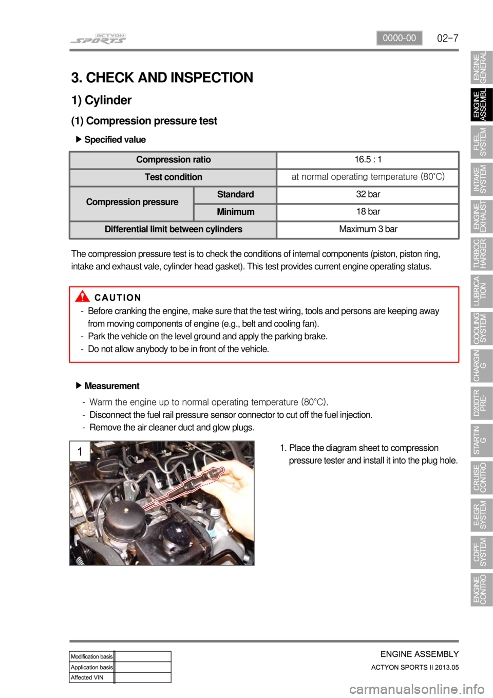
Place the diagram sheet to compression
pressure tester and install it into the plug hole. 1.
Page 44 of 751
02-130000-00
D20DTR Engine
1. BELT LAYOUT
It is single drive type and uses FEAD (Front End Accessories Drive) design to make a compact layout.
Components ▶
HPS (Hydraulic Power Steering)
1 Crankshaft pulley (DDU)
2 Auto tensioner
3 Tensioner pulley
4 Vacuum pump
5 A/C compressor pulley
6 Alternator pulley
7 Water pump pulley
8 Idle pulley #1
9 Idle pulley #2
10 Power steering pump pulley
Page 45 of 751
02-14
The strut type tensioner automatically adjusts the belt tension to provide the reliability and durability for
the system. And, the belt tension is decreased to minimize the friction loss and improve the belt
operating noise.
1) Crankshaft Pulley (Isolation Damper)
(1) Overview
(2) Sectional drawing
Axial & radial bearing
Sleeve
Hub
Isolation pulley rubber Pulley
Damper rubber
Inertia ring
Page 46 of 751
02-150000-00
(3) Features
Rubber damper: Decrease crankshaft torsion
Improve belt NHV: Reduce unbalance speed to crankshaft due to irregular combustion
Minimize noise: Anti-vibration from crankshaft and belt
Post bonded type rubber damper: Improve durability of rubber damper 1.
2.
3.
4.
Page 47 of 751
02-16
2) Belt Tensioner
(1) Overview
The torque deviation from crankshaft affects the components in belt drive system and the belt
movement. The auto tensioner system is to adjust this deviation automatically.
In D20DTR engine, one of the mechanical tensioner, pivot damped tensioner is used to keep the
damping force, system reliability and durability. The single belt drive system needs to use the automatic
belt tensioning device to transfer the power to pulleys effectively. To get this, the tensioner uses the
spring and damping unit.
(2) Location
Belt tensioner
Page 146 of 751
08-8
Oil filter module
Thermostat
When the engine coolant
reaches 90℃, the thermostat
starts to open (fully open at
100℃) and lets the coolant
flow to the radiator to maintain
the engine temperature.
Water pump
The water pump is driven by the engine drive belt and supplies
the coolant to each area of the engine.
Coolant reservoir
Long life coolant is used.
1. SYSTEM DESCRIPTION
1) Overview
Water pump
Impeller vane Sealing
Page 150 of 751

09-51451-01
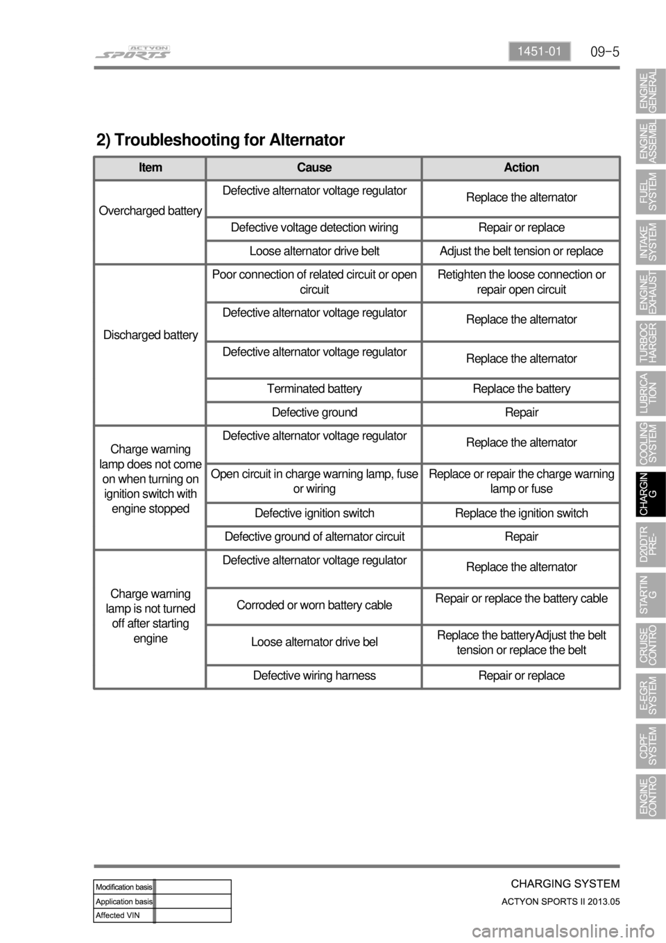
2) Troubleshooting for Alternator
Item Cause Action
Overcharged batteryDefective alternator voltage regulator
Replace the alternator
Defective voltage detection wiring Repair or replace
Loose alternator drive belt Adjust the belt tension or replace
Discharged batteryPoor connection of related circuit or open
circuitRetighten the loose connection or
repair open circuit
Defective alternator voltage regulator
Replace the alternator
Defective alternator voltage regulator
Replace the alternator
Terminated battery Replace the battery
Defective ground Repair
Charge warning
lamp does not come
on when turning on
ignition switch with
engine stoppedDefective alternator voltage regulator
Replace the alternator
Open circuit in charge warning lamp, fuse
or wiringReplace or repair the charge warning
lamp or fuse
Defective ignition switch Replace the ignition switch
Defective ground of alternator circuit Repair
Charge warning
lamp is not turned
off after starting
engineDefective alternator voltage regulator
Replace the alternator
Corroded or worn battery cableRepair or replace the battery cable
Loose alternator drive belReplace the batteryAdjust the belt
tension or replace the belt
Defective wiring harness Repair or replace