Page 553 of 751

09-4
2. SYSTEM OVERVIEW
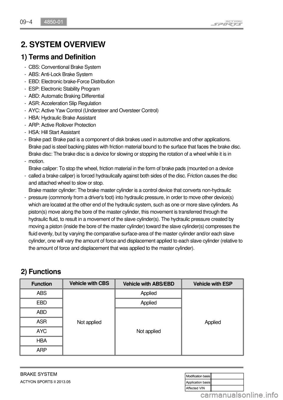
1) Terms and Definition
CBS: Conventional Brake System
ABS: Anti-Lock Brake System
EBD: Electronic brake-Force Distribution
ESP: Electronic Stability Program
ABD: Automatic Braking Differential
ASR: Acceleration Slip Regulation
AYC: Active Yaw Control (Understeer and Oversteer Control)
HBA: Hydraulic Brake Assistant
ARP: Active Rollover Protection
HSA: Hill Start Assistant
Brake pad: Brake pad is a component of disk brakes used in automotive and other applications.
Brake pad is steel backing plates with friction material bound to the surface that faces the brake disc.
Brake disc: The brake disc is a device for slowing or stopping the rotation of a wheel while it is in
motion.
Brake caliper: To stop the wheel, friction material in the form of brake pads (mounted on a device
called a brake caliper) is forced hydraulically against both sides of the disc. Friction causes the disc
and attached wheel to slow or stop.
Brake master cylinder: The brake master cylinder is a control device that converts non-hydraulic
pressure (commonly from a driver's foot) into hydraulic pressure, in order to move other device(s)
which are located at the other end of the hydraulic system, such as one or more slave cylinders. As
piston(s) move along the bore of the master cylinder, this movement is transferred through the
hydraulic fluid, to result in a movement of the slave cylinder(s). The hydraulic pressure created by
moving a piston (inside the bore of the master cylinder) toward the slave cylinder(s) compresses the
fluid evenly, but by varying the comparative surface-area of the master cylinder and/or each slave
cylinder, one will vary the amount of force and displacement applied to each slave cylinder (relative to
the amount of force and displacement that was applied to the master cylinder). -
-
-
-
-
-
-
-
-
-
-
-
-
-
FunctionVehicle with CBS
Vehicle with ABS/EBD Vehicle with ESP
ABS
Not appliedApplied
Applied EBD Applied
ABD
Not applied ASR
AYC
HBA
ARP
2) Functions
Page 554 of 751
09-54850-01
3) Parts Arrangement
Part nameVehicle with
CBSVehicle with ABS/EBDVehicle with ESP
HECU
Not appliedAppliedApplied Front wheel speed sensor
Rear wheel speed sensor
ABS warning lamp
EBD indicator
Longitudinal G sensor 2WD: N/A, 4WD: Applied Not applied
Sensor cluster
(Yaw rate sensor,
lateral/longitudinal G sensor)
Not applied Applied
ESP indicator
ESP OFF switch and warning
lamp
Steering wheel angle sensor
4) Components
ABS ESP+ARP
2WD 4WD 2WD 4WD
Whhel speed sensor 4 4 4 4
Sensor cluster N/A N/A Applied Applied
G-sensor N/A Applied N/A N/A
2H G-sensor - Operating - -
4H G-sensor - Operating - -
4L G-sensor - Operating - -
2H sensor cluster - - Operating Operating
4H sensor cluster - - Operating Operating
4L sensor cluster - - Operating Operating
Page 558 of 751
09-94850-01
Problem Cause Action
Burning smell around
tireToo frequent braking in high driving speed Reduce the use of
foot brake/use
engine brake
properly Used only foot brake during downhill driving
Driving with foot on brake pedal Get off the foot from
pedal
Foreign materials such as dirt or sand in brake system Replace: caliper,
wheel cylinder,
master cylinder,
return spring
Broken return spring in shoe assembly Replace
Incorrectly adjusted parking brake cable Adjust
Incorrect wheel or wheel cover
(generating the heat)Replace
Page 570 of 751
09-214850-01
Check the brake force with below procedures:
Count the number of the clicks (notches)
when pulling up the parking brake with 19 kg
of force.
If the clicks are over or below the specified
value, adjust the clicks to the specified value
with the parking brake adjusting nut.
Check the parking brake force afte
r
adjustment. 1.
2.
3.
Specified notches5
If the parking brake force is not enough,
check the parking brake lever and cable.
Replace the components if needed. 4.
Never park the vehicle only with the parking
brake on the stiff hill. It may cause roll down of
the vehicle due to release of the parking
brake. Place the wheel chocks under the
wheels. Parking Brake ▶
Page 575 of 751

09-26
1. OVERVIEW
Even though a driver cuts off the power, while driving, the vehicle continues to move due to the law of
inertia. Therefore, a braking device is needed to stop the vehicle. The brake system normally uses the
frictional discs that converts the kinetic energy to the thermal energy by frictional operation. The brake
system consists of the brake disc (front wheel), brake disc or drum (rear wheel), parking brake
(mechanical type), master cylinder, booster, pedal and supply lines (pipes and hoses).
Hydraulic Brake ▶
Brake Pedal ▶This system uses the leverage effect and
Pascal's principle. When depressing the brake
pedal, the pedal pressure is increased by
booster and is delivered to master cylinder to
generate hydraulic pressure. The hydraulic
pressure generated by the master cylinder is
delivered to the brake caliper through the brake
pipes or hoses. This hydraulic pressure pushes
the brake calipers, accordingly the caliper pads
are contacted to brake disc to generate the
braking force.
Brake pedal uses the leverage effect to apply
bigger force to the brake master cylinder.
Page 577 of 751
09-28
Front Brake AssemblyFront Wheel Speed Sensor (4WD)
HECU
2. SYSTEM LAYOUT
Master Cylinder and Booster
Brake Pedal
Page 578 of 751
09-294850-01
Rear Wheel Speed Sensor (4WD)
Rear Brake Assembly
ABS/EBD Indicators
Parking Brake Lever
Parking Brake
Page 583 of 751
10-34892-01
1. SPECIFICATION
Unit DescriptionSpecification
Remark
ABS ESP
HECU Clock frequency 32MHz 50MHz
Memory 128KB 256KB
S-sensor Operating voltage 4.75~5.25V
None (functions in
sensor cluster)Installed in IP
panel behind
audio (only for
4WD) Operating temperature-30 ~ 85℃
Operating range -1.5 ~ 1.5g
Output voltage 0.5 ~ 4.5V
Wheel speed
sensorSupplying voltage 4.5 ~ 16V←
Output current (approx. 2.7
km/h of vehicle speed)7mA(Lo) ~ 14mA
+20%←
Operating temperature-40 ~ 150℃ ←
Operating frequency 1~2500Hz←