Page 547 of 751
08-10
2. FRONT SUSPENSION (DOUBLE WISHBONE)
Advantage ▶
The advantage of a double wishbone suspension is that it is fairly easy to work out the effect of
moving each joint, so the kinematics of the suspension can be tuned easily and wheel motion can
be optimized.
It is also easy to work out the loads that different parts will be subjected to which allows more
optimized lightweight parts to be designed.
They also provide increasing negative camber gain all the way to full jounce travel unlike the
MacPherson strut which provides negative camber gain only at the beginning of jounce travel and
then reverses into positive camber gain at high jounce amounts. 1.
2.
3.
Disadvantage ▶
The disadvantage is that it is slightly more complex than other systems like a MacPherson strut. Due to
the increased number of components within the suspension setup it takes much longer to service and is
heavier than an equivalent MacPherson design. 1.
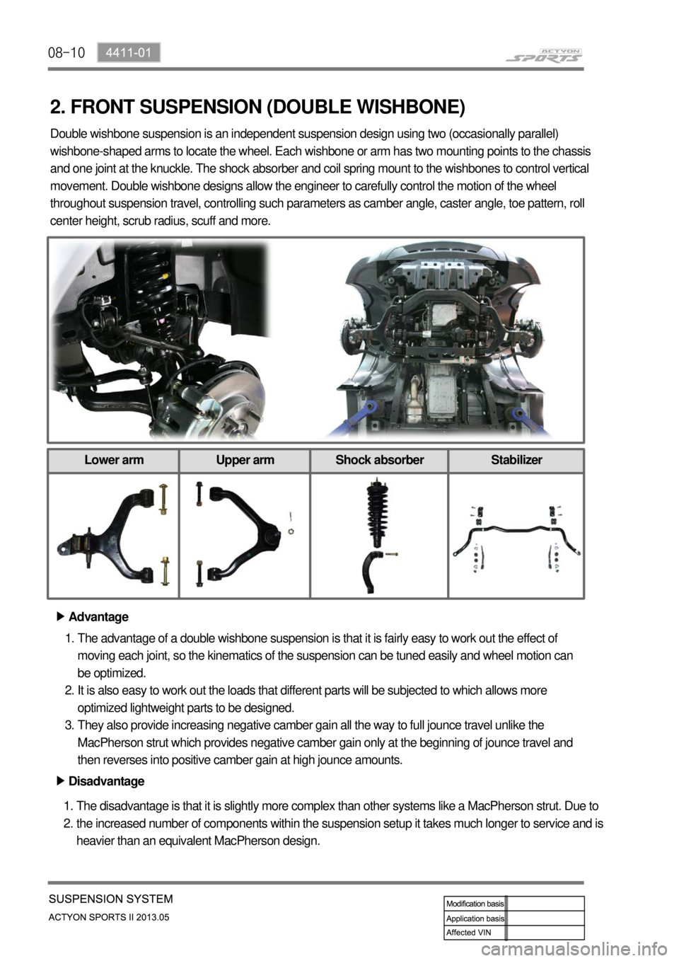
2. Double wishbone suspension is an independent suspension design using two (occasionally parallel)
wishbone-shaped arms to locate the wheel. Each wishbone or arm has two mounting points to the chassis
and one joint at the knuckle. The shock absorber and coil spring mount to the wishbones to control vertical
movement. Double wishbone designs allow the engineer to carefully control the motion of the wheel
throughout suspension travel, controlling such parameters as camber angle, caster angle, toe pattern, roll
center height, scrub radius, scuff and more.
Lower arm Upper arm Shock absorber Stabilizer
Page 559 of 751
09-10
This section describes the noise phenomena occurred possibly in the brake system operation.
Distinguish between the information given below and the actual problems and then, inspect the vehicle
and take appropriate measures.
Noise symptoms and Causes -
Symptom 1. If depressing the brake pedal when the engine is cold, "screeching" sound always
occurs and, after driving for a while, the sound disappears..
This usually occurs in the morning. When the temperature goes down, the dew condensation
phenomenon sets moisture on the brake disc as the window frost forms. Due to this moisture, the iron
within the brake disc and pad oxidizes, forming undetectable micro-rusts on the disc surface. When
starting the engine under this condition, noise may sound due to the friction of micro-rusts. When
operating the brake several times, the disc temperature goes up and the micro-rusts come off and the
noise goes away. Depending on the driving conditions, noise gets louder when slightly depressing the
brake pedal and oppositely, noise is smaller when deeply depressing the brake pedal. This is simply a
physical phenomenon, called "morning effect" in professional terms, and does not imply any problems
with the brake system.
Symptom 2. Slip or screech after the brake pad replacement.
This usually occurs when the bed-in is not made between the disc and the pad's friction material. The
bed-in is a state that the brake system normally works and gives no noise out, when, after about 300 km
city driving, the contact area of the pad friction material is enlarged and the disk is in complete contact
with the pad's friction material. Therefore, for some time after the brake disk/pad replacement, the brake
system poorly operates or noise (abnormal sound) occurs due to the partial contact.
Symptom 3. "Groaning" sound occurs in the automatic transmission vehicle when slightly taking the foot
off the brake pedal to slowly start after waiting for the signal, or slightly depressing the brake pedal.
This is the noise "Creep groan" that occurs when, in both the automatic and manual transmission,
slightly releasing the brake pedal in the neutral gear at downhill roads.
It frequently occurs at the low braking power and low speed, through the following process. When
operating the brake system at low speed and low pressure, adhesion and slip repeatedly take place
between the brake disk and the friction material, and this makes the braking power inconstant, instantly
increasing or decreasing, and gives out the brake noise.
It is also a physical phenomenon and has no relation with the brake performance.BRAKE OPERATION AND NOISE ▶
Page 659 of 751
13-94620-01
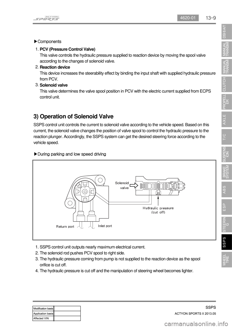
▶Components
PCV (Pressure Control Valve)
This valve controls the hydraulic pressure supplied to reaction device by moving the spool valve
according to the changes of solenoid valve.
Reaction device
This device increases the steerability effect by binding the input shaft with supplied hydraulic pressure
from PCV.
Solenoid valve
This valve determines the valve spool position in PCV with the electric current supplied from ECPS
control unit. 1.
2.
3.
3) Operation of Solenoid Valve
SSPS control unit controls the current to solenoid valve according to the vehicle speed. Based on this
current, the solenoid valve changes the position of valve spool to control the hydraulic pressure to the
reaction plunger. Accordingly, the SSPS system can get the desired steering force according to the
vehicle speed.
▶During parking and low speed driving
SSPS control unit outputs nearly maximum electrical current.
The solenoid rod pushes PCV spool to right side.
The hydraulic pressure coming from pump is not supplied to the reaction device as the spool
orifice is cut off.
The hydraulic pressure is cut off and the manipulation of steering wheel becomes lighter. 1.
2.
3.
4.
Page 661 of 751
13-114620-01
4) System Control
ECPS system, according to the vehicle speed,
enables to achieve proper steering
characteristics by controlling hydraulic
pressure to reaction plunger located in input
shaft of power steering gear box. In other words,
ECPS control unit enhances the parking
conveniences by controlling duty type current
control. It provides heavy steerability with low
current as the vehicle speed increases. And, it
provides light steerability with high current as the
vehicle speed decreases.
▶During parking and low speed driving
During parking and driving in low speed, the control unit supplies approx. 1 A of electric current to
solenoid valve. Then, the spool located in PCV compresses the upper spring and elevates upward and,
the working pressure from oil pump (A port) is not able to flow to the reaction plunger (C port). As a
result, the pressing force from reaction plunger disappears and the steerability enhances.
Page 674 of 751
14-134170-09
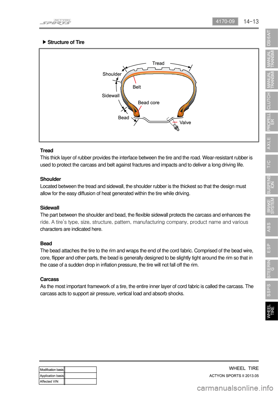
Structure of Tire ▶
Tread
This thick layer of rubber provides the interface between the tire and the road. Wear-resistant rubber is
used to protect the carcass and belt against fractures and impacts and to deliver a long driving life.
Shoulder
Located between the tread and sidewall, the shoulder rubber is the thickest so that the design must
allow for the easy diffusion of heat generated within the tire while driving.
Sidewall
The part between the shoulder and bead, the flexible sidewall protects the carcass and enhances the
<00990090008b008c0055004700680047009b00900099008c02c5009a0047009b00a00097008c00530047009a009000a1008c00530047009a009b0099009c008a009b009c0099008c0053004700970088009b009b008c009900950053004700940088009500
9c008d0088008a009b009c009900900095008e0047008a0096>mpany, product name and various
characters are indicated here.
Bead
The bead attaches the tire to the rim and wraps the end of the cord fabric. Comprised of the bead wire,
core, flipper and other parts, the bead is generally designed to be slightly tight around the rim so that in
the case of a sudden drop in inflation pressure, the tire will not fall off the rim.
Carcass
As the most important framework of a tire, the entire inner layer of cord fabric is called the carcass. The
carcass acts to support air pressure, vertical load and absorb shocks.
Page 688 of 751
01-96810-01
▶ Step 5
Ambient
temperature
display
51
Interior
temperature
displayIntake air
temperature display
Ambient
temperature
sensorInterior
temperature
sensorIntake air temperature
sensor
▶ Step 6
To enter the step 6 from 5, turn the fan speed dial lightly toward the right not using the
temperature control dial. In this step, you can decrease or increase by up to 3 degrees from the
temperature set on the A/C controller. -You can check that the temperature value from each temperature sensor is displayed properly in
this step. Pressing the defroster switch changes the temperature value that appears on the
display in the order as follows: -
2) Self-diagnosis step
(1) Step 1
Turn the ignition ON and press the OFF switch for 5 sec. or more within 10 sec.
Then the first step of the self-diagnosis is started as shown in the below figure.
2. Display for checking VFD and all LED segments
1. Press OFF switch for 5 sec. or more
Page 689 of 751
01-10
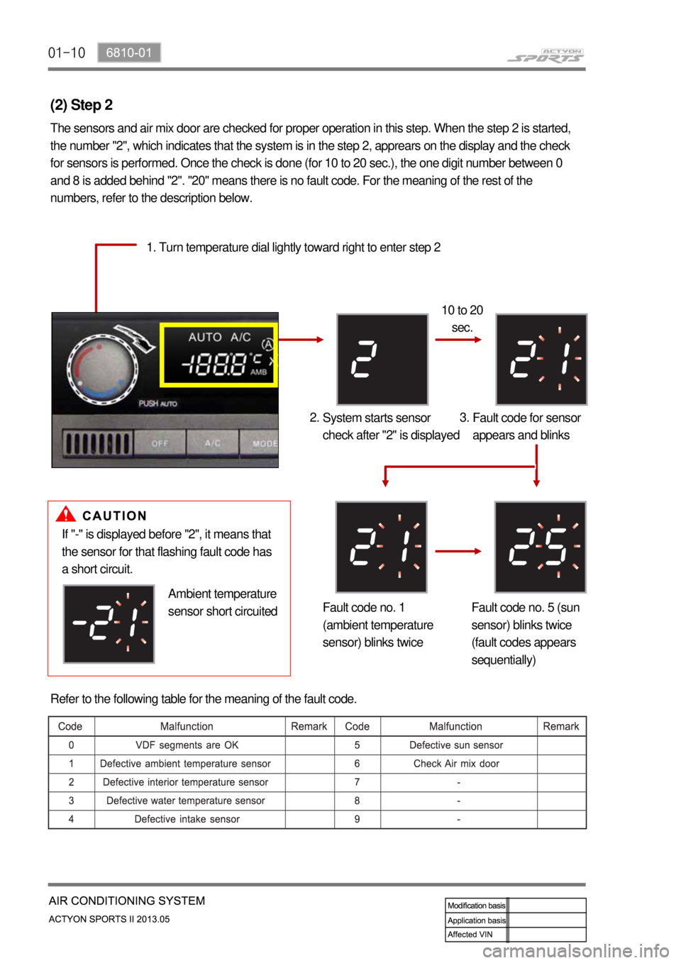
(2) Step 2
The sensors and air mix door are checked for proper operation in this step. When the step 2 is started,
the number "2", which indicates that the system is in the step 2, apprears on the display and the check
for sensors is performed. Once the check is done (for 10 to 20 sec.), the one digit number between 0
and 8 is added behind "2". "20" means there is no fault code. For the meaning of the rest of the
numbers, refer to the description below.
1. Turn temperature dial lightly toward right to enter step 2
10 to 20
sec.
System starts sensor
check after "2" is displayed 2.
Fault code for sensor
appears and blinks 3.
Fault code no. 1
(ambient temperature
sensor) blinks twiceFault code no. 5 (sun
sensor) blinks twice
(fault codes appears
sequentially)
If "-" is displayed before "2", it means that
the sensor for that flashing fault code has
a short circuit.
Ambient temperature
sensor short circuited
Refer to the following table for the meaning of the fault code.
Page 690 of 751
01-116810-01
(3) Step 3
In this step, you can check the position and condition of the air source door and mode door. To start step
3, turn the temperature control dial lightly toward the right and confirm that the number 3 appears on the
display. It takes several tens of seconds to finish the check. If there is no fault code, "30" is displayed.
And if there is a malfunction, the corresponding fault code is added as described in the step 2.
Turn temperature dial lightly toward
right to enter step 3 1.
System starts sensor
check after "3" is
displayed 2. Fault code for
sensor appears and
blinks (30 is
displayed when
there is no fault) 3.
Refer to the following table for the meaning of the fault code.