Page 867 of 1336
Initialization mode after IGN ON, ESP disabled due to failure, during ESP operation (blink), under
diagnostic mode, indicator lamp ON in instrument cluster, impossible to communicate with CAN
module. -ESP warning lamp module
The ESP warning lamp shows self-diagnosis result of ESP function and whether there is a fault. The
ESP warning lamp comes on when:
Page 872 of 1336
8510-00
Multifunction wiper switches
2) Multifunction Switch
Multifunction light switches
Light switch
Front wiper switch
Wiper speed dial
Rear wiper switch Front fog lamp switch
Front auto washer switch The multifunction switch contains the auto washer and wiper switch, front fog lamp switch and auto
hazard warning flasher switch. For the vehicle with air bag, since the contact coil is fitted to the upper part
of the multifunction switch and ESP steering wheel angle sensor is fitted to upper part of the contact coil,
pay attention to when removing and fitting or checking the wiring.
Page 897 of 1336
(4) License lamp operation process
When the corresponding lamp comes on and
goes off by operating the tail lamp, AUTO light,
high beam and low beam on the multifunction
switch, the license lamp also does.
Page 927 of 1336

7810-00
1. WIPER CONTROL
2. CAUTIONS ON RAIN SENSOR
When the wiper switch is in the AUTO position, the wiper will operate for 1 cycle if the initial engine
start is made. This may cause the wiper blades to wear prematurely. Therefore, other than rainy
days, set the switch to the OFF position. Especially during the winter time, check if the wiper blades
are not frozen to the windshield.
Operating the wiper with the blades frozen can damage the wiper motor.
If you operate the wipers when the windshield is dry without spraying washer fluid, the windshield
can be scratched and the wiper blades can wear prematurely. Use the wiper with the washer fluid
when the windshield is dry.
When it does not rain, turn the wiper switch to the OFF position.
Turn the wiper switch to the OFF position before any car wash to avoid unwanted operation of the
wipers. -
-
-
-Wiper mist & washer coupled wiper
Auto washer coupled wiper
Rain sensor coupled wiper operation (LIN)
Speed sensitive intermittent wiper
Wiper low/high control
Check if the sensor is off the position.
Check if the rain sensor cover is securely installed.
Check if the customer is familiar to how to control the wiper sensitivity.
Check if the wiper sensitivity control is set to the FAST side (step 5).
Check the wiper blade for wear.
If the wiper blade cannot wipe the glass uniformly and clearly, it may cause the rain sensor to work
irregularly. Therefore, in this case, replace the wiper blade with a new one. -
-
-
-
-Irregular operation (abrupt operation)
When cleaning the windshield over the sensor with damp clothes, the wiper may operate suddenly. It
could cause serious injury. Make sure to place the wiper switch to the OFF position and ignition switch
OFF when not in use.
Page 959 of 1336
8910-05
1. SPECIFICATION
Unit Item Specification
AudioVoltage DC 14.4 V
Speaker impedance
Max. power 45 watts x 4 ch
Weight 2,244 g
Size 310.4 mm (W) x 275.7 mm (H) x 209 mm (D)
RadioFrequencyFM: 87.5 MHz ~ 108.0 MHz
AM: 531 kHz ~ 1,602 kHz
SensitivityFM: 18 dBu
AM: 35 dBu
S/N ratio
(Signal/noise ratio)FM: 45 db
AM: 40 db
Stereo channel separation
FM: 20 db
MP3 [WMA]/USB Frequency response 20 Hz ~ 20 kHz
S/N ratio
(Signal/noise ratio)60 dB
Channel response 54 dB
MP3 [WMA]/CDFrequency response
S/N ratio
(Signal/noise ratio)50 dB
Channel response 35 dB
BluetoothFrequency 2,402 ~ 2,480 MHz
SpecificationSupports headset, hands-free, A2DP and AVRCP
profile formats
(Headset, hands-free: profile for calling)
(A2DP, AVRCP: profile for listening music)
Page 984 of 1336

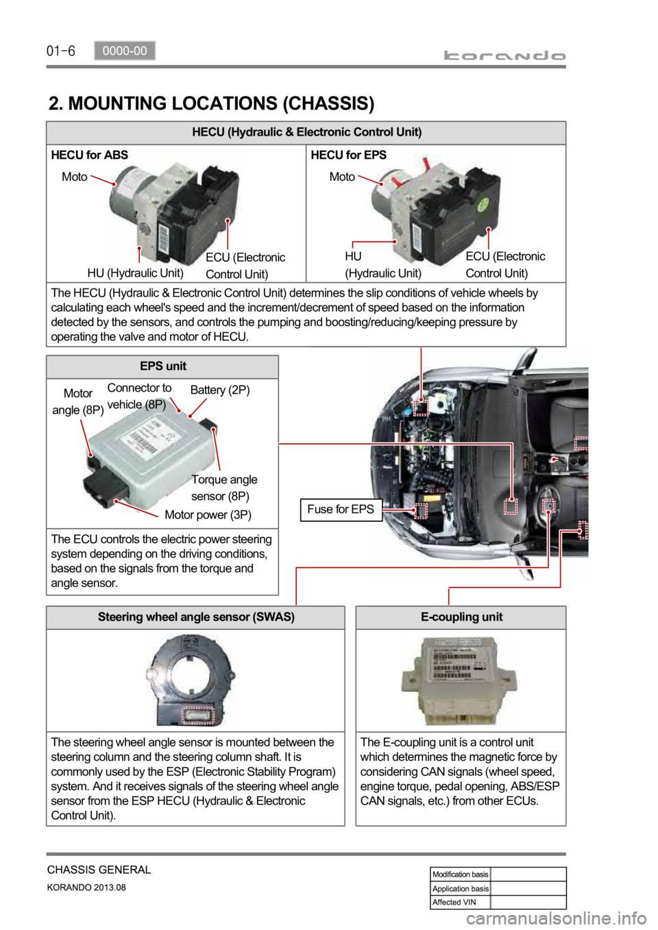
HECU (Hydraulic & Electronic Control Unit)
HECU for ABS HECU for EPS
The HECU (Hydraulic & Electronic Control Unit) determines the slip conditions of vehicle wheels by
calculating each wheel's speed and the increment/decrement of speed based on the information
detected by the sensors, and controls the pumping and boosting/reducing/keeping pressure by
operating the valve and motor of HECU.
2. MOUNTING LOCATIONS (CHASSIS)
Moto
HU (Hydraulic Unit) ECU (Electronic
Control Unit) Moto
HU
(Hydraulic Unit) ECU (Electronic
Control Unit)
Motor
angle (8P)
Motor power (3P)Torque angle
sensor (8P) Battery (2P) Connector to
vehicle (8P)
Fuse for EPS
Steering wheel angle sensor (SWAS)
The steering wheel angle sensor is mounted between the
steering column and the steering column shaft. It is
commonly used by the ESP (Electronic Stability Program)
system. And it receives signals of the steering wheel angle
sensor from the ESP HECU (Hydraulic & Electronic
Control Unit).
EPS unit
The ECU controls the electric power steering
system depending on the driving conditions,
based on the signals from the torque and
angle sensor.
E-coupling unit
The E-coupling unit is a control unit
which determines the magnetic force by
considering CAN signals (wheel speed,
engine torque, pedal opening, ABS/ESP
CAN signals, etc.) from other ECUs.
Page 985 of 1336

0000-00
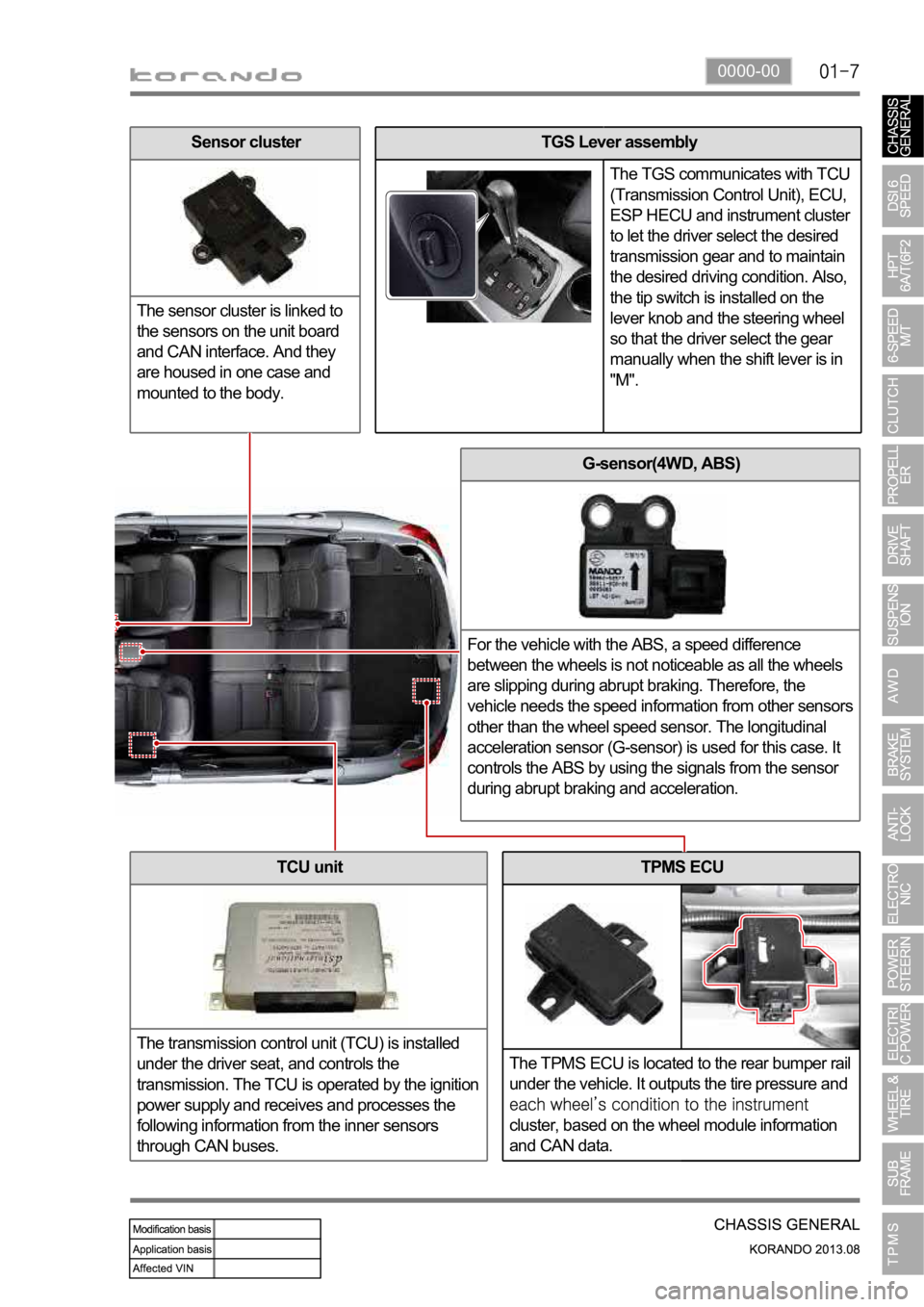
TPMS ECU
The TPMS ECU is located to the rear bumper rail
under the vehicle. It outputs the tire pressure and
cluster, based on the wheel module information
and CAN data.
G-sensor(4WD, ABS)
For the vehicle with the ABS, a speed difference
between the wheels is not noticeable as all the wheels
are slipping during abrupt braking. Therefore, the
vehicle needs the speed information from other sensors
other than the wheel speed sensor. The longitudinal
acceleration sensor (G-sensor) is used for this case. It
controls the ABS by using the signals from the sensor
during abrupt braking and acceleration.
TCU unit
The transmission control unit (TCU) is installed
under the driver seat, and controls the
transmission. The TCU is operated by the ignition
power supply and receives and processes the
following information from the inner sensors
through CAN buses.
TGS Lever assembly
The TGS communicates with TCU
(Transmission Control Unit), ECU,
ESP HECU and instrument cluster
to let the driver select the desired
transmission gear and to maintain
the desired driving condition. Also,
the tip switch is installed on the
lever knob and the steering wheel
so that the driver select the gear
manually when the shift lever is in
"M".Sensor cluster
The sensor cluster is linked to
the sensors on the unit board
and CAN interface. And they
are housed in one case and
mounted to the body.
Page 986 of 1336

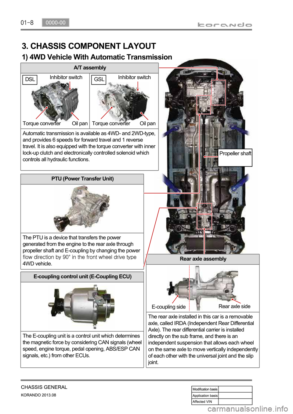
A/T assembly
Automatic transmission is available as 4WD- and 2WD-type,
and provides 6 speeds for forward travel and 1 reverse
travel. It is also equipped with the torque converter with inner
lock-up clutch and electronically controlled solenoid which
controls all hydraulic functions.
3. CHASSIS COMPONENT LAYOUT
PTU (Power Transfer Unit)
The PTU is a device that transfers the power
generated from the engine to the rear axle through
propeller shaft and E-coupling by changing the power
4WD vehicle.Rear axle assembly
The rear axle installed in this car is a removable
axle, called IRDA (Independent Rear Differential
Axle). The rear differential carrier is installed
directly on the sub frame, and there is an
independent suspension that allows each wheel
on the same axle to move vertically independentl
y
of each other with the universal joint and the slip
joint.
E-coupling control unit (E-Coupling ECU)
The E-coupling unit is a control unit which determines
the magnetic force by considering CAN signals (wheel
speed, engine torque, pedal opening, ABS/ESP CAN
signals, etc.) from other ECUs.
Inhibitor switch
Torque converter Oil pan
E-coupling sideRear axle side
Propeller shaft
1) 4WD Vehicle With Automatic Transmission
GSLDSLInhibitor switch
Torque converter Oil pan