Page 1137 of 1336

Circuit description
When compared to the vehicle equipped with ABS/EBD only, the internal hydraulic circuit has a
normally-open separation valve and a shuttle valve in primary circuit and in secondary circuit.
When the vehicle brakes are not applied during engine running or when applying the non-ABS operating
brakes, the normally-open separation valve and the inlet valve are open, whereas the normally-closed
shuttle valve and the outlet valve are closed.
When the ESP system is operating, the normally-open separation valve will be closed by the solenoid
valve operation and the hydraulic circuit will be established by the shuttle valve. Then, the inlet and outlet
valves will be closed or open depending on the braking pressure RISE, HOLD or DUMP conditions.
Flashing warning lamp and warning sound during ESP operation
When the ESP operates while the vehicle is moving, the ESP warning lamp on the instrument panel
flickers and the buzzer sounds at every 0.1 second. The ESP lamp operation is to inform a driver that the
vehicle is extremely unstable.
The ESP system is just a supplementary system for the vehicle and it cannot control the vehicle over the
physical limit. Do not solely rely on the system but be advised to drive the vehicle safely.
Drive feeling during ESP operation
When the ESP system activates, the driving feeling can be different depending on vehicle driving
conditions. For example, it will feel different when the ESP system is activated while the ABS is operated
by depressing the brake pedal and when the ESP system is in control without the brake pedal
depressed on the same curve.
If the ESP system operates with the brake applied, the brake pressure will be increased on the
corresponding wheel which already has braking pressure for the ESP controls. In other words, the ESP
system would make the driver feel more abruptly braked compared to the situation that the braking
pressure is applied to wheel which had no braking force.
Noise and vibration that driver senses during ESP operation
The ESP system may transfer noise and vibration to a driver due to the pressure changes caused by the
motor and valve operations in a very short period of time.
Extreme cornering will trigger the ESP operation and this will make the driver sense noise and vibration
due to sudden brake application.
Also, the ESP system controls the engine power. Therefore, the driver may notice the engine power
decreases even when the accelerator pedal is depressed.
Page 1139 of 1336
2) DUMP (ESP is working) Mode
The pressure decreases just before the wheel speed drops and the wheels are locked.
The inlet valve closes and the outlet valve opens as in the ABS HECU and the oil is gathered at the low
pressure chamber while no additional oil is being supplied. Then the pump operates to allow fast oil
drainage. The shuttle valve and the separation valve do not operate while decompression.
Page 1140 of 1336
0000-00
3) HOLD (ESP is working) Mode
The Inlet valve and outlet valve will be closed to maintain the pressure in the hydraulic circuit applied at
the wheels. By closing the valves, the hydraulic pressure at the wheels will not be lost or supplied any
more. During ESP operation, the separation valve closes and only the shuttle valve at the pump opens.
Page 1141 of 1336
4) RISE (ESP is working) Mode
The shuttle valve and inlet valve will be open and the separation valve and outlet valve will be closed.
Then, the pump is operated. When ESP operates while the ABS is operating, the pressure will be
increased continuously until just before the corresponding wheel gets locked.
Page 1142 of 1336
0000-00
5) Hydraulic Circuit of HBA
The above figure shows one front and one rear wheel and the same hydraulic circuit forms as in the ESP
operation. When HECU recognizes that it is an emergency and it is required for hard braking, depending
on the pressure value of the brake pressure sensor and pressure changes caused by the pressure sensor
timing, it operates the pump immediately to apply the brake pressure at the wheels. Then, the pressure in
the pump increases until just before the corresponding wheel gets locked. The motor still keeps rotating
and the outlet valve and the separation valve will stay closed. When the wheel starts to lock, the HBA
function cancels and switches to ABS operation.
Page 1143 of 1336
7. CIRCUIT DIAGRAM
Wheel speed sensor, Stop lamp switch, Self diagnostic connector, Warning lamp (ABS/ESP)
Page 1162 of 1336

If weight is not equally distributed around the wheel, unbalance centrifugal force by the wheel rotation
produces vibration. As the centrifugal force is produced proportional to the square of the rotating speed,
the wheel weight should be balanced even at high speed. There are two types of the tire and wheel
balancing: static and dynamic. Abnormal vibration may also occur due to unbalanced rigidity or size of
tires.
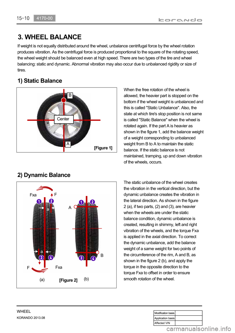
1) Static Balance
When the free rotation of the wheel is
allowed, the heavier part is stopped on the
bottom if the wheel weight is unbalanced and
this is called "Static Unbalance". Also, the
state at which tire's stop position is not same
is called "Static Balance" when the wheel is
rotated again. If the part A is heavier as
shown in the figure 1, add the balance weight
of a weight corresponding to unbalanced
weight from B to A to maintain the static
balance. If the static balance is not
maintained, tramping, up and down vibration
of the wheels, occurs.
2) Dynamic Balance
The static unbalance of the wheel creates
the vibration in the vertical direction, but the
dynamic unbalance creates the vibration in
the lateral direction. As shown in the figure
2 (a), if two parts, (2) and (3), are heavier
when the wheels are under the static
balance condition, dynamic unbalance is
created, resulting in shimmy, left and right
vibration of the wheels, and the torque Fxa
is applied in the axial direction. To correct
the dynamic unbalance, add the balance
weight of a same weight for two points of
the circumference of the rim, A and B, as
shown in the figure 2 (b), and apply the
torque in the opposite direction to the
torque Fxa to offset in order to ensure
smooth rotation of the wheel.
Center
A
B
a
a
Fxa
Fxa F
F
A
B
(a)(b)
[Figure 1]
[Figure 2]
3. WHEEL BALANCE
Page 1183 of 1336

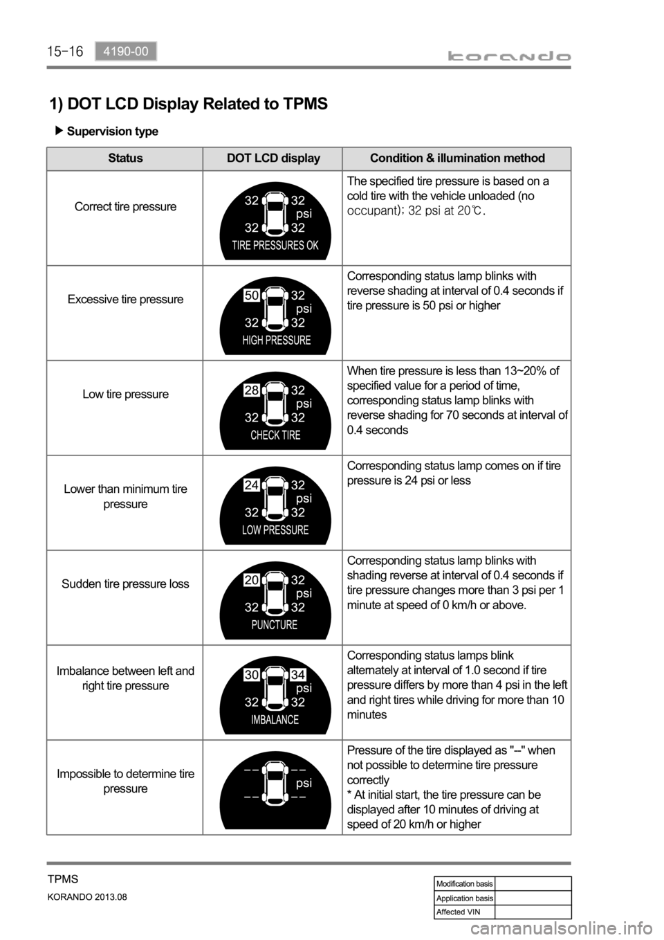
1) DOT LCD Display Related to TPMS
Status DOT LCD display Condition & illumination method
Correct tire pressureThe specified tire pressure is based on a
cold tire with the vehicle unloaded (no
Excessive tire pressureCorresponding status lamp blinks with
reverse shading at interval of 0.4 seconds if
tire pressure is 50 psi or higher
Low tire pressureWhen tire pressure is less than 13~20% of
specified value for a period of time,
corresponding status lamp blinks with
reverse shading for 70 seconds at interval o
f
0.4 seconds
Lower than minimum tire
pressureCorresponding status lamp comes on if tire
pressure is 24 psi or less
Sudden tire pressure lossCorresponding status lamp blinks with
shading reverse at interval of 0.4 seconds if
tire pressure changes more than 3 psi per 1
minute at speed of 0 km/h or above.
Imbalance between left and
right tire pressureCorresponding status lamps blink
alternately at interval of 1.0 second if tire
pressure differs by more than 4 psi in the left
and right tires while driving for more than 10
minutes
Impossible to determine tire
pressurePressure of the tire displayed as "--" when
not possible to determine tire pressure
correctly
* At initial start, the tire pressure can be
displayed after 10 minutes of driving at
speed of 20 km/h or higher
Supervision type