Page 1072 of 1336
1. OVERVIEW
The propeller shaft is a thin steel pipe which transfers the power from the transmission to the E-coupling,
and has high resistance to torsion and bending.
The propeller shaft has the universal joint (cross axle) mounted on the center of the shaft and splines for
the slip joint on the E-coupling side to accommodate the height and length changes which occur as the
shaft rotates at high speed.
And the rubber bushing for center bearing in the center of the propeller shaft keeps the balance of the
shaft and absorbs its vibration.
Function of propeller shaft
Transmits driving torque.
Accommodates the angle change (universal joint / CV joint).
Accommodates the axial length change (splines for the slip joint). -
-
-
CV joint
Universal yoke and
center bearingUniversal yoke and
rubber coupling
Page 1168 of 1336
The front sub frame consists of 4 body bush mountings(A) and 2 engine bush mountings(B) which
reduce the vibration from the powertrain and road, and also control the torque. And the two engine bush
mountings consist of an engine mounting which supports the engine powertrain and a transmission
mounting.
The engine side and transmission side mountings are rubber mountings with brackets and insulators
while the body mounting is a rubber bush mounting which is fitted to the frame.
Installation of front sub
frame (4WD)The installation of the front sub frame is the same for both automatic
transmission and manual transmission. For 4WD, the PTU and the
propeller shaft are installed.
Installation of front sub
frame (2WD)The installation of the front sub frame is the same for both automatic
transmission and manual transmission.
PTU assembly
Page 1169 of 1336
4015-01
Installation of rear sub
frame (4WD)The installation of the rear sub frame is the same for both automatic
transmission and manual transmission. For 4WD, the E-coupling, propeller
shaft and rear axle are installed.
Installation of rear sub
frame (2WD) The installation of the rear sub frame is the same for both automatic
transmission and manual transmission.
The rear sub frame system consists of body bush mountings and direct mountings which reduce the
vibration transmitted from the powertrain and road to the vehicle body.
For 4WD, it consists of 4 body mountings (bush mountings) and 2 axle mountings (bush mountings) and
for 2WD, it consists of 4 body mountings (direct mountings).
Page 1175 of 1336
Instrument cluster display related to TPMS (with standard)
DOT LCD display TPMS warning lamp Global warning lamp
2. LAYOUT 1. OVERVIEW
The TPMS is used to reduce the accident rate, enhance driving stability and avoid an unnecessary fuel
consumption and tire wear by monitoring the tire pressure and temperature to inform the driver of tire
pressure information and its status through the instrument cluster. The wheel module fitted in the tire
transmits the internal data for the tire to the TPMS ECU periodically through the wireless transmission.
The TPMS ECU can detect the positions of the wheel modules fitted to each wheel automatically and
sends the signal on tire condition through the CAN line to the instrument cluster so that the driver can
identify the wheel module in question.
Instrument cluster display related to TPMS (with supervision)
DOT LCD display TPMS warning lamp Global warning lamp
Page 1178 of 1336

4190-00
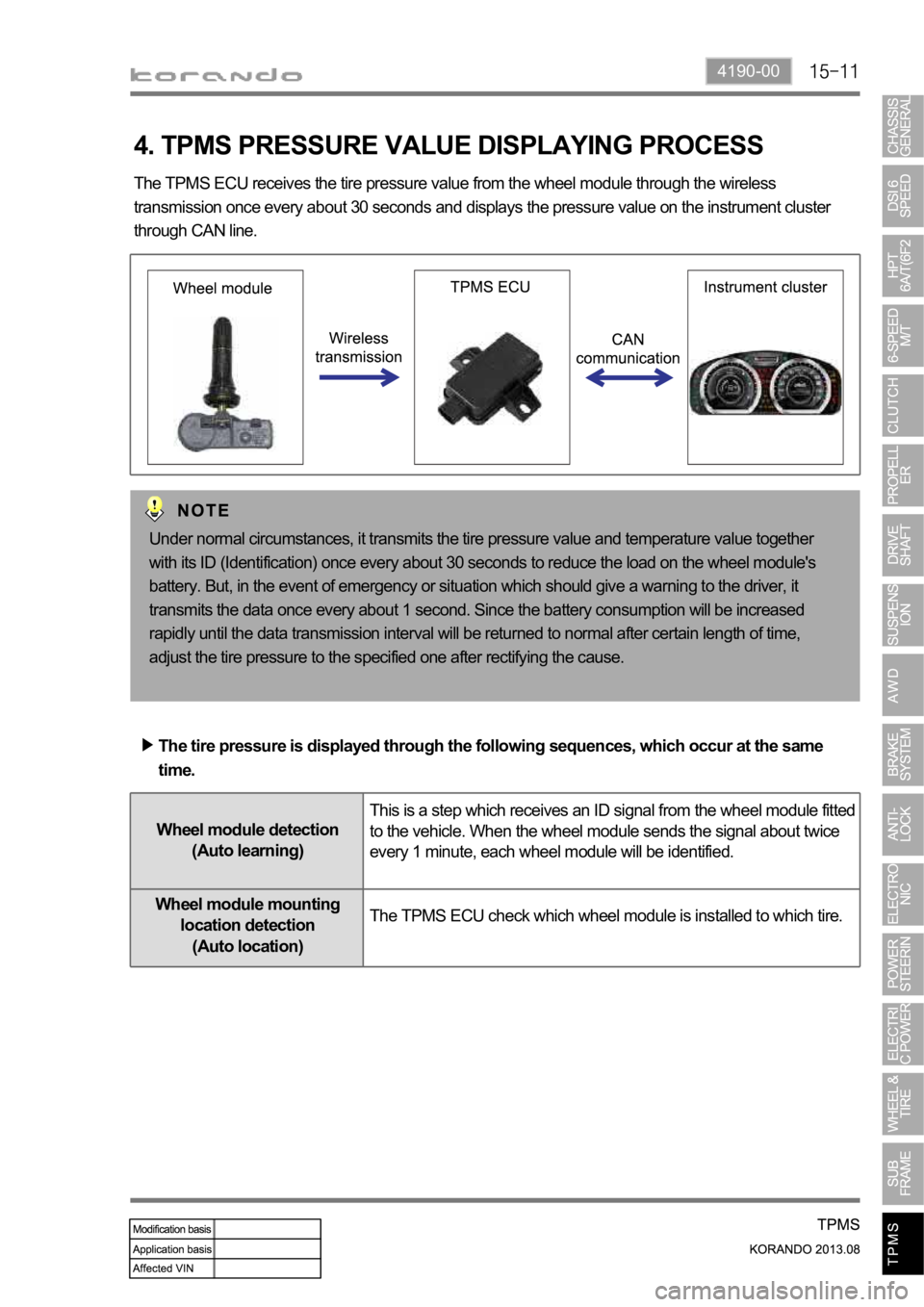
4. TPMS PRESSURE VALUE DISPLAYING PROCESS
The TPMS ECU receives the tire pressure value from the wheel module through the wireless
transmission once every about 30 seconds and displays the pressure value on the instrument cluster
through CAN line.
Under normal circumstances, it transmits the tire pressure value and temperature value together
with its ID (Identification) once every about 30 seconds to reduce the load on the wheel module's
battery. But, in the event of emergency or situation which should give a warning to the driver, it
transmits the data once every about 1 second. Since the battery consumption will be increased
rapidly until the data transmission interval will be returned to normal after certain length of time,
adjust the tire pressure to the specified one after rectifying the cause.
The tire pressure is displayed through the following sequences, which occur at the same
time.
Wheel module detection
(Auto learning)This is a step which receives an ID signal from the wheel module fitted
to the vehicle. When the wheel module sends the signal about twice
every 1 minute, each wheel module will be identified.
Wheel module mounting
location detection
(Auto location)The TPMS ECU check which wheel module is installed to which tire.
Page 1185 of 1336

7. TIRE INFLATION PROCEDURE FOR VEHICLE WITH TPMS
1) Overview
For the vehicle with TPMS, the tire should be inflated in a method different from the conventional method
since the tire pressure values displayed on the tire pressure gauge and instrument cluster are different
after inflation.
The tire pressure displayed on the instrument cluster should be checked after a certain time delay
(wireless transmission time for wheel module).
The displayed value can be changed after driving even if it was set to the specified value.
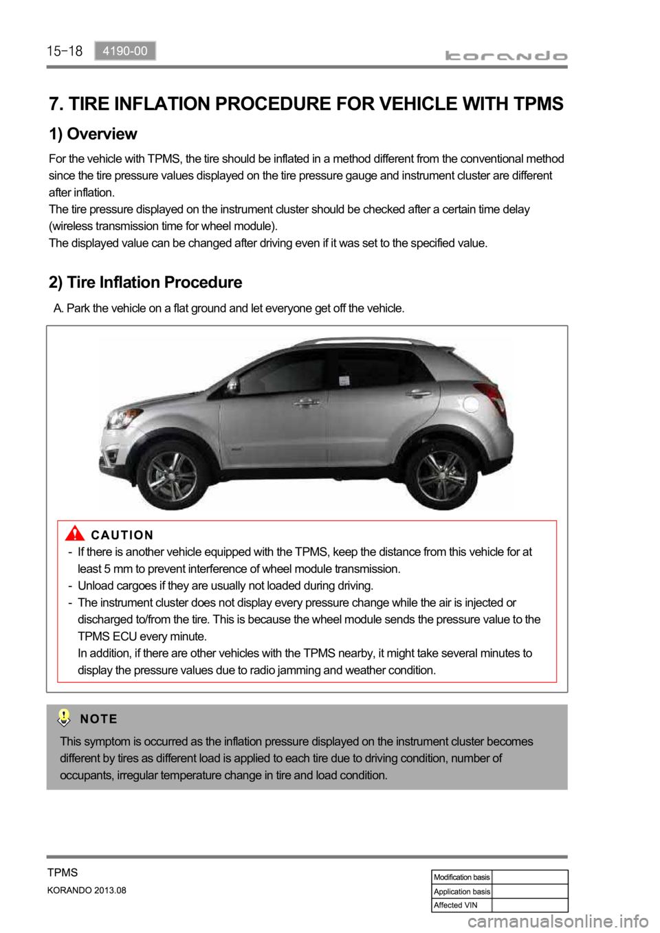
2) Tire Inflation Procedure
Park the vehicle on a flat ground and let everyone get off the vehicle. A.
This symptom is occurred as the inflation pressure displayed on the instrument cluster becomes
different by tires as different load is applied to each tire due to driving condition, number of
occupants, irregular temperature change in tire and load condition.
If there is another vehicle equipped with the TPMS, keep the distance from this vehicle for at
least 5 mm to prevent interference of wheel module transmission.
Unload cargoes if they are usually not loaded during driving.
The instrument cluster does not display every pressure change while the air is injected or
discharged to/from the tire. This is because the wheel module sends the pressure value to the
TPMS ECU every minute.
In addition, if there are other vehicles with the TPMS nearby, it might take several minutes to
display the pressure values due to radio jamming and weather condition. -
-
-