Page 1148 of 1336

1. SYSTEM DESCRIPTION
The power steering has been designed to make the wheel move more easily than in a manual steering
system. The hydraulic power assists the process utilizing hydraulic fluid. The fluid increases pressure in
the power steering pump and aids the movement of the steering mechanism.
The power steering system consists of pump, oil reservoir, rack and gear box.
The power steering pump is a vane type and delivers hydraulic pressure to operate the power steering
system.
The pressure relief valve in the pump controls the discharging pressure.
The rotary valve in the rack and the pinion gear directs the oil from the power steering pump to one side
of the rack piston. The integrated rack piston converts the hydraulic pressure to linear movement. The
operating force of the rack moves the wheels through the tie rod, the tie rod end and the steering knuckle.
Even though the hydraulic pressure cannot be generated, a driver can steer the vehicle without power
assist but it needs very high steering force.
In this case, the operating force of the steering wheel is conveyed to the pinion, and the movement of the
pinion moves the rack through the pinion gear combined to the rack gear.
Page 1150 of 1336
4610-00
1. SPECIFICATION
Unit Description Specification
System operationOperating type Motor driven power steering system
Operating temperature
Rated voltage 12 V
Rated current 85 A
Operating voltageNetwork 8 to 16 V
C-EPS ECU 8 to 16 V
Full Performance 10 to 16 V
MotorType 3-Phase BLAC (Brushless AC)
Rated current/voltage 85 A / 12 V (at idle 0.5 A)
Position sensor type Hall sensor type
Torque & angle sensorType Non-contact type
Steering columnOperating type Manual tilting & telescoping
Lower shaftType Sliding (Ball slip) type
Steering gearGear ratio 50.7 mm/rev
Rack stroke 145 mm
Maximum steering angleInner wheel
Outer wheel
Page 1153 of 1336

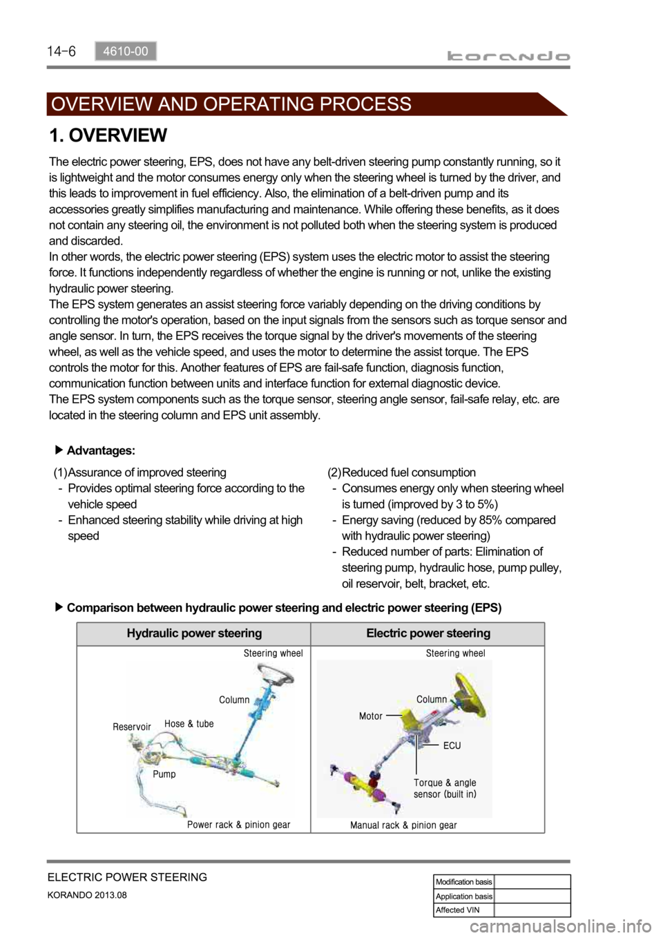
Hydraulic power steering Electric power steering
1. OVERVIEW
The electric power steering, EPS, does not have any belt-driven steering pump constantly running, so it
is lightweight and the motor consumes energy only when the steering wheel is turned by the driver, and
this leads to improvement in fuel efficiency. Also, the elimination of a belt-driven pump and its
accessories greatly simplifies manufacturing and maintenance. While offering these benefits, as it does
not contain any steering oil, the environment is not polluted both when the steering system is produced
and discarded.
In other words, the electric power steering (EPS) system uses the electric motor to assist the steering
force. It functions independently regardless of whether the engine is running or not, unlike the existing
hydraulic power steering.
The EPS system generates an assist steering force variably depending on the driving conditions by
controlling the motor's operation, based on the input signals from the sensors such as torque sensor and
angle sensor. In turn, the EPS receives the torque signal by the driver's movements of the steering
wheel, as well as the vehicle speed, and uses the motor to determine the assist torque. The EPS
controls the motor for this. Another features of EPS are fail-safe function, diagnosis function,
communication function between units and interface function for external diagnostic device.
The EPS system components such as the torque sensor, steering angle sensor, fail-safe relay, etc. are
located in the steering column and EPS unit assembly.
Advantages:
Assurance of improved steering
Provides optimal steering force according to the
vehicle speed
Enhanced steering stability while driving at high
speed (1)
-
-Reduced fuel consumption
Consumes energy only when steering wheel
is turned (improved by 3 to 5%)
Energy saving (reduced by 85% compared
with hydraulic power steering)
Reduced number of parts: Elimination of
steering pump, hydraulic hose, pump pulley,
oil reservoir, belt, bracket, etc. (2)
-
-
-
Comparison between hydraulic power steering and electric power steering (EPS)
Page 1154 of 1336
4610-00
2. OPERATION
When the driver turns the steering wheel, a torque is generated and the torque sensor and the steering
angle sensor in the EPS system detect the rotation of the steering column to run the electric motor. At
this time, the worm gear connected to the motor drives the helical gear mounted to the steering column
to generate the assist torque for the steering column. This allows the driver to operate the steering wheel
easier.Output torque = 1) Steering force (manual torque) + 2) Assist torque
Page 1229 of 1336

3. CAUTIONS FOR AIR BAG SYSTEM
Cautions for air bag maintenance
Whenever installing or removing the devices related to the air bag system, disconnect the negative
battery cable and wait for at least 30 seconds.
Do not connect a tester probe to the inflator to measure the resistance of the component of the air
bag system. The detonator of the inflator may explode due to a sudden extra power supplied by the
tester.
Note that the used components related to the air bag system, especially the air bag unit, should be
packed in an air tight container and prevent it from any impact or damage.
When there is any deployed air bag (including curtain air bag and seat belt pretensioner), the entire
system including the air bag unit should be replaced. The deployed air bag unit should not be reused
since it has status data when it is deployed, and the data cannot be cleared with a diagnostic device.
The air bag and seat belt pretensioner systems contain explosive charges, so handle carefully when
disposing or replacing them. 1.
2.
3.
4.
5.
Cautions for air bag maintenance
Do not modify, change or apply impact on any air bag component. The air bag may be deployed
abruptly, causing serious injuries.
Children and infants should ride in a rear seat. Seating in the passenger seat with carrying a
child or infant is strictly prohibited. An infant or a child could be severely injured by the air bag
deployment.
A child restraint system must not be installed on the front seat. An infant or a child could be severely
injured by the air bag deployment when it is fitted to the passenger seat.
Do not place any objects on the air bag inflation location. You may get injured by those objects during
deployment.
Never put your arms around the front seat from behind, lean on the front seatback, or put your arms
out of the window. You can severely injured when the side air bag deploys.
Never lean on the door since it becomes very dangerous when the side air bag deploys.
The side air bag deploys when there is a severe side collision.
Do not slam the front door to close it. The side air bag may deploy unexpectedly.
When an occupant fastens the seat belt in an unstable or inclined posture, the air bag system cannot
protect the occupant properly. Moreover, the occupant can be injured by the air bag.
Do not move your seat too close to the steering wheel or dashboard. Being too close to the
steering wheel or instrument panel during the air bag deployment could cause serious injury,
including death
Hold only the outer rim of the steering so that the air bag can inflate without any hindrance.
Do not incline toward the steering wheel. Never allow the passenger to put hands or feet on the dash
board. The air bag cannot work properly Do not hold and operate the steering wheel by crossing your
arms You could get seriously injured when the air bag deploys. 1.
2.
3.
4.
5.
6.
7.
8.
9.
10.
11.
Page 1233 of 1336

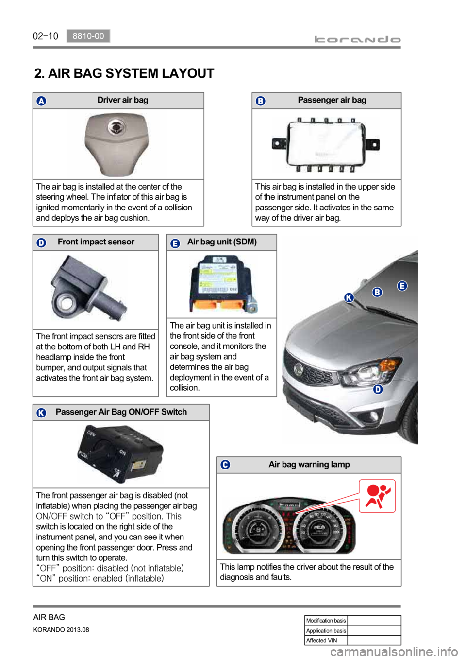
Driver air bag
The air bag is installed at the center of the
steering wheel. The inflator of this air bag is
ignited momentarily in the event of a collision
and deploys the air bag cushion.
Air bag unit (SDM)
The air bag unit is installed in
the front side of the front
console, and it monitors the
air bag system and
determines the air bag
deployment in the event of a
collision.Front impact sensor
The front impact sensors are fitted
at the bottom of both LH and RH
headlamp inside the front
bumper, and output signals that
activates the front air bag system.
Air bag warning lamp
This lamp notifies the driver about the result of the
diagnosis and faults.
Passenger air bag
This air bag is installed in the upper side
of the instrument panel on the
passenger side. It activates in the same
way of the driver air bag.
2. AIR BAG SYSTEM LAYOUT
Passenger Air Bag ON/OFF Switch
The front passenger air bag is disabled (not
inflatable) when placing the passenger air bag
switch is located on the right side of the
instrument panel, and you can see it when
opening the front passenger door. Press and
turn this switch to operate.