Page 352 of 1336
6) Normal Cancellation of the Cruise Control
The cruise control system will be canceled when one or more items of the following conditions are
applied;
When the brake pedal is depressed.
When the cruising speed is decreased less than 38 km/h.
When pushing the ON-OFF switch of the cruise control lever.
When ESP is activated.
When applying the parking brake while driving.
When using the clutch in order to shift (M/T only).
To cancel the cruise control function, pull the cruise switch toward you. (GSL only). 1.
2.
3.
4.
5.
6.
7.
Keep the main cruise control switch in the neutral position when not using the cruise control.
And the cruise control system can be operated again in driving state.
Page 555 of 1336
6) Normal Cancellation of the Cruise Control
The cruise control system will be canceled when one or more items of the following conditions are
applied;
When the brake pedal is depressed.
When the cruising speed is decreased less than 38 km/h.
When pushing the ON-OFF switch of the cruise control lever.
When ESP is activated.
When applying the parking brake while driving.
When using the clutch in order to shift (M/T only).
To cancel the cruise control function, pull the cruise switch toward you. (GSL only). 1.
2.
3.
4.
5.
6.
7.
Keep the main cruise control switch in the neutral position when not using the cruise control. And the cruise control system can be operated again in driving state.
Page 986 of 1336
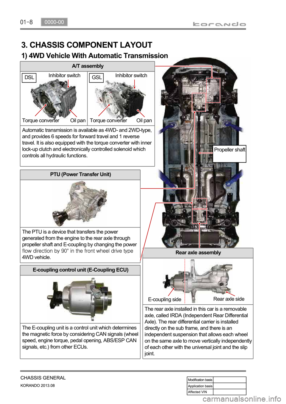
A/T assembly
Automatic transmission is available as 4WD- and 2WD-type,
and provides 6 speeds for forward travel and 1 reverse
travel. It is also equipped with the torque converter with inner
lock-up clutch and electronically controlled solenoid which
controls all hydraulic functions.
3. CHASSIS COMPONENT LAYOUT
PTU (Power Transfer Unit)
The PTU is a device that transfers the power
generated from the engine to the rear axle through
propeller shaft and E-coupling by changing the power
4WD vehicle.Rear axle assembly
The rear axle installed in this car is a removable
axle, called IRDA (Independent Rear Differential
Axle). The rear differential carrier is installed
directly on the sub frame, and there is an
independent suspension that allows each wheel
on the same axle to move vertically independentl
y
of each other with the universal joint and the slip
joint.
E-coupling control unit (E-Coupling ECU)
The E-coupling unit is a control unit which determines
the magnetic force by considering CAN signals (wheel
speed, engine torque, pedal opening, ABS/ESP CAN
signals, etc.) from other ECUs.
Inhibitor switch
Torque converter Oil pan
E-coupling sideRear axle side
Propeller shaft
1) 4WD Vehicle With Automatic Transmission
GSLDSLInhibitor switch
Torque converter Oil pan
Page 987 of 1336
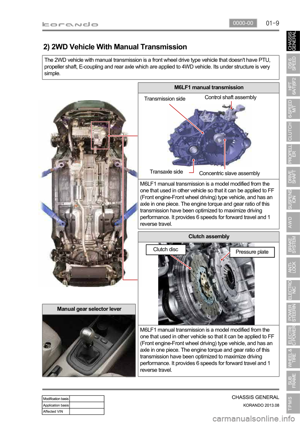
0000-00
M6LF1 manual transmission
M6LF1 manual transmission is a model modified from the
one that used in other vehicle so that it can be applied to FF
(Front engine-Front wheel driving) type vehicle, and has an
axle in one piece. The engine torque and gear ratio of this
transmission have been optimized to maximize driving
performance. It provides 6 speeds for forward travel and 1
reverse travel.
Clutch assembly
M6LF1 manual transmission is a model modified from the
one that used in other vehicle so that it can be applied to FF
(Front engine-Front wheel driving) type vehicle, and has an
axle in one piece. The engine torque and gear ratio of this
transmission have been optimized to maximize driving
performance. It provides 6 speeds for forward travel and 1
reverse travel.
The 2WD vehicle with manual transmission is a front wheel drive type vehicle that doesn't have PTU,
propeller shaft, E-coupling and rear axle which are applied to 4WD vehicle. Its under structure is very
simple.
Manual gear selector lever
Transmission sideControl shaft assembly
Transaxle side
Concentric slave assembly
Pressure plate
2) 2WD Vehicle With Manual Transmission
Clutch disc
Page 1003 of 1336
3680-01
1. GENERAL INFORMATION
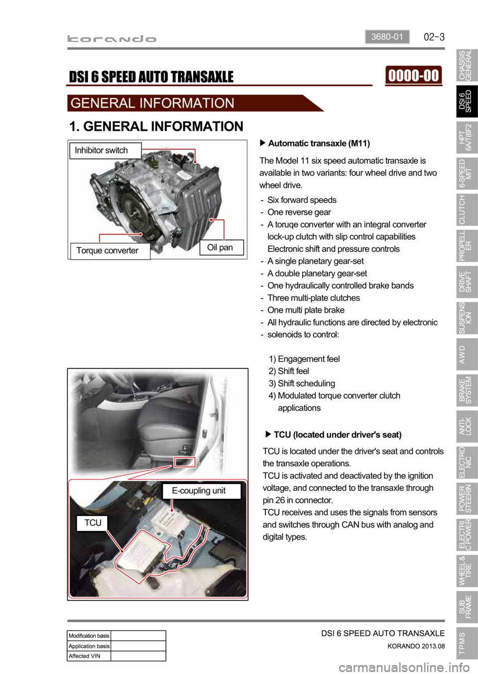
Automatic transaxle (M11)
The Model 11 six speed automatic transaxle is
available in two variants: four wheel drive and two
wheel drive.
Six forward speeds
One reverse gear
A toruqe converter with an integral converter
lock-up clutch with slip control capabilities
Electronic shift and pressure controls
A single planetary gear-set
A double planetary gear-set
One hydraulically controlled brake bands
Three multi-plate clutches
One multi plate brake
All hydraulic functions are directed by electronic
solenoids to control: -
-
-
-
-
-
-
-
-
-
Engagement feel
Shift feel
Shift scheduling
Modulated torque converter clutch
applications 1)
2)
3)
4) Inhibitor switch
Oil pan
Torque converter
TCU (located under driver's seat)
TCU is located under the driver's seat and controls
the transaxle operations.
TCU is activated and deactivated by the ignition
voltage, and connected to the transaxle through
pin 26 in connector.
TCU receives and uses the signals from sensors
and switches through CAN bus with analog and
digital types.
E-coupling unit
TCU
Page 1008 of 1336
1. OVERVIEW
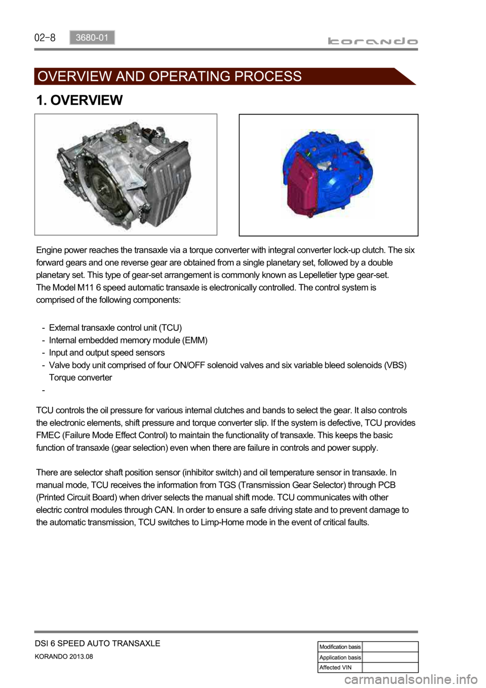
Engine power reaches the transaxle via a torque converter with integral converter lock-up clutch. The six
forward gears and one reverse gear are obtained from a single planetary set, followed by a double
planetary set. This type of gear-set arrangement is commonly known as Lepelletier type gear-set.
The Model M11 6 speed automatic transaxle is electronically controlled. The control system is
comprised of the following components:
External transaxle control unit (TCU)
Internal embedded memory module (EMM)
Input and output speed sensors
Valve body unit comprised of four ON/OFF solenoid valves and six variable bleed solenoids (VBS)
Torque converter -
-
-
-
-
TCU controls the oil pressure for various internal clutches and bands to select the gear. It also controls
the electronic elements, shift pressure and torque converter slip. If the system is defective, TCU provides
FMEC (Failure Mode Effect Control) to maintain the functionality of transaxle. This keeps the basic
function of transaxle (gear selection) even when there are failure in controls and power supply.
There are selector shaft position sensor (inhibitor switch) and oil temperature sensor in transaxle. In
manual mode, TCU receives the information from TGS (Transmission Gear Selector) through PCB
(Printed Circuit Board) when driver selects the manual shift mode. TCU communicates with other
electric control modules through CAN. In order to ensure a safe driving state and to prevent damage to
the automatic transmission, TCU switches to Limp-Home mode in the event of critical faults.
Page 1010 of 1336
2) Transaxle Cooling
The transaxle cooling system ensures rapid warm-up and constant operating temperature resulting in
reduced fuel consumption and refined shift quality.
It also includes a cooler by-pass within the hydraulic system to allow sufficient lubrication to the transaxle
drivetrain in the event of a blockage in the transaxle cooler.
3) Shift Strategy
Gear Change
Transaxle gear change is controlled by the
TCU. The TCU receives inputs from various
engine and vehicle sensors to select shift
schedules and to control the shift feel and
torque converter clutch (TCC) operation at each
gear change.
Coast down
Coast down down shifts occur at 0% pedal
when the vehicle is coasting down to a stop.
Torque Demand
Torque demand down shifts occur
(automatically) when the driver demand for
torque is greater than the engine can provide at
that gear ratio. If applied, the transaxle will
disengage the TCC to provide added
acceleration.
Page 1013 of 1336
3680-01
4. LIMP HOME MODE
When the transaxle is defective
In the event of a system fault, the TCU also provides for failure mode effect control (FMEC) to maintain
maximum functional operation of the transaxle.
In the event of a total loss of control or electrical power, the basic transaxle functions (Park, Reverse,
Neutral and Drive) are retained. The 4th and reverse gear ratios with the torque converter clutch in the
unlocked state are the retained gear states the hydraulic system supports without any electrical
assistance.
The TCU communicates with other vehicle electronic control modules by the controller area network
(CAN). If a major fault develops, the transaxle may automatically operate in a "limp home" (failure)
mode to enable the vehicle to be driven to an authorized dealer for repair.
The TCU also provides for transaxle diagnostics, which meet the requirements of OBD II legislation,
monitoring all components which may effect vehicle emissions. 1.
2.
3.
4.
When the transaxle overheats
Limp home mode may also be engaged if the battery charge falls below 8V.
If the transaxle overheats, the shift patterns will automatically change to enable improved transaxle
cooling.
During transaxle overheat, the instrument cluster transaxle selector position display and the over
cluster until normal transaxle operating temperature is reached. 1.
2.
3.
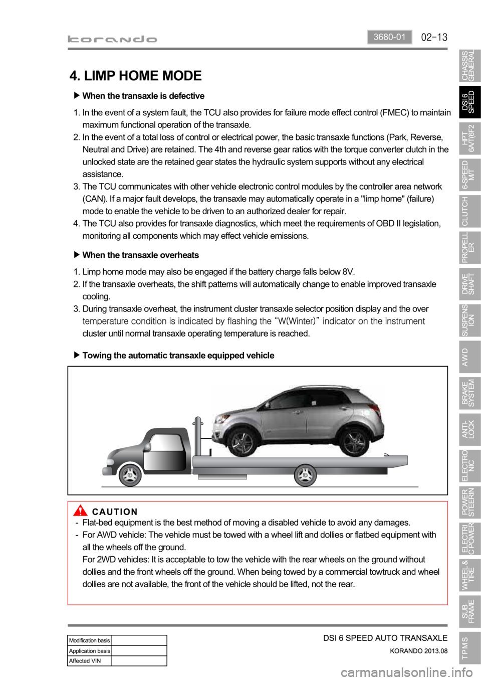
Towing the automatic transaxle equipped vehicle
Flat-bed equipment is the best method of moving a disabled vehicle to avoid any damages.
For AWD vehicle: The vehicle must be towed with a wheel lift and dollies or flatbed equipment with
all the wheels off the ground.
For 2WD vehicles: It is acceptable to tow the vehicle with the rear wheels on the ground without
dollies and the front wheels off the ground. When being towed by a commercial towtruck and wheel
dollies are not available, the front of the vehicle should be lifted, not the rear. -
-