Page 1102 of 1336
3. G-sensor (for 4WD)
Located on the floor under
parking brake bracket in center
console.4. Rear wheel speed sensor
(for 2WD)
Located on knuckle. The
appearance is different from that
for 4WD.4. Wheel speed sensor
(for 4WD)
Located on knuckle. The
appearance of front sensor is
same with rear sensor.
2. ABS warning lamp
EBD warning lamp (ABS warning lamp +
Brake warning lamp)1. ABS hydraulic device and control unit
Located under the power steering fluid reservoir and
contains the pressure sensor.
2. COMPONENT
Page 1122 of 1336
0000-00
1. OVERVIEW
The ESP (Electronic Stability Program) has been developed to help a driver avoid danger of losing
control of the vehicle stability due to understeer or oversteer during cornering. The yaw rate sensor,
lateral sensor and longitudinal sensor in the sensor cluster and the steering wheel angle sensor under
the steering column detect the vehicle conditions when the inner or outer wheels are spinning during
oversteer, understeer or cornering. The ESP ECU controls against oversteer or understeer during
cornering by controlling the vehicle stability using input values from these sensors and applying the
braking force to the corresponding wheels independently. The system also controls the engine power
right before the wheel spin synchronized to decelerate the vehicle automatically in order to maintain the
vehicle stable during cornering.
Page 1123 of 1336
3. ESP OFF switch
Located on the left side of
instrument panel.2. Steering wheel angle
sensor
Located on column shaft with
contact coil.1. HECU assembly
Located under the power
steering fluid reservoir and
contains the pressure sensor.
2. COMPONENTS
4. Sensor cluster
Located on the floor under front
passenger seat.5. Wheel speed sensor
(4WD/2WD-front)
Located on knuckle. the
appearance of front sensor is
same with rear sensor.6. Rear wheel speed sensor
(2WD)
Located on knuckle. The
appearance is different from
that for 4WD.
Page 1128 of 1336

0000-00
2) Operation of ESP System
The ESP (Electronic Stability Program) has been developed to help a driver avoid danger of losing
control of the vehicle stability due to understeer or oversteer during cornering. The yaw rate sensor,
lateral sensor and longitudinal sensor in the sensor cluster and the steering wheel angle sensor under
the steering column detect the vehicle conditions when the inner or outer wheels are spinning during
oversteer, understeer or cornering. The ESP ECU controls against oversteer or understeer during
cornering by controlling the vehicle stability using input values from these sensors and applying the
braking force to the corresponding wheels independently. The system also controls the engine power
right before the wheel spin synchronized with the ASR function to decelerate the vehicle automatically in
order to maintain the vehicle stable during cornering.
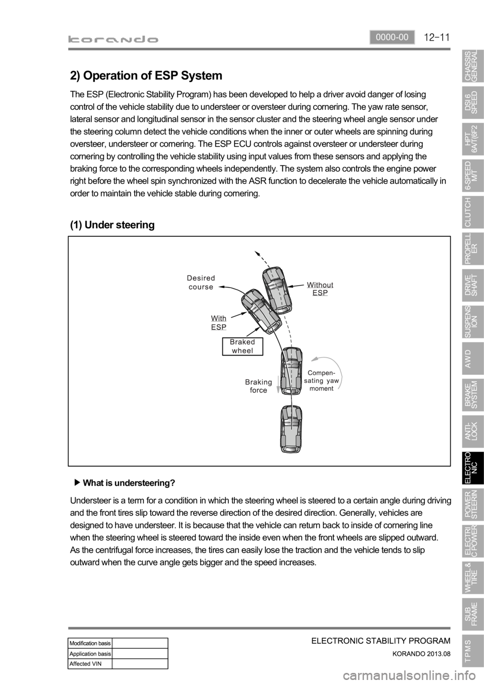
(1) Under steering
What is understeering?
Understeer is a term for a condition in which the steering wheel is steered to a certain angle during driving
and the front tires slip toward the reverse direction of the desired direction. Generally, vehicles are
designed to have understeer. It is because that the vehicle can return back to inside of cornering line
when the steering wheel is steered toward the inside even when the front wheels are slipped outward.
As the centrifugal force increases, the tires can easily lose the traction and the vehicle tends to slip
outward when the curve angle gets bigger and the speed increases.
Page 1132 of 1336

0000-00
5) ARP (Active Roll-Over Protection)
The ARP (Active Roll-over Protection) system is a safety assistant device that minimizes, by controlling
brakes and the engine, the physical tendency of the vehicle rollover during sharp lane changes or U-
turns. For the system, software is added to the existing ESP system and no additional device or switch is
needed. One must note that the ARP system, just as general assistant devices including the ABS, is only
a safety assistant device using the ESP system and its function is useless when the situation overcomes
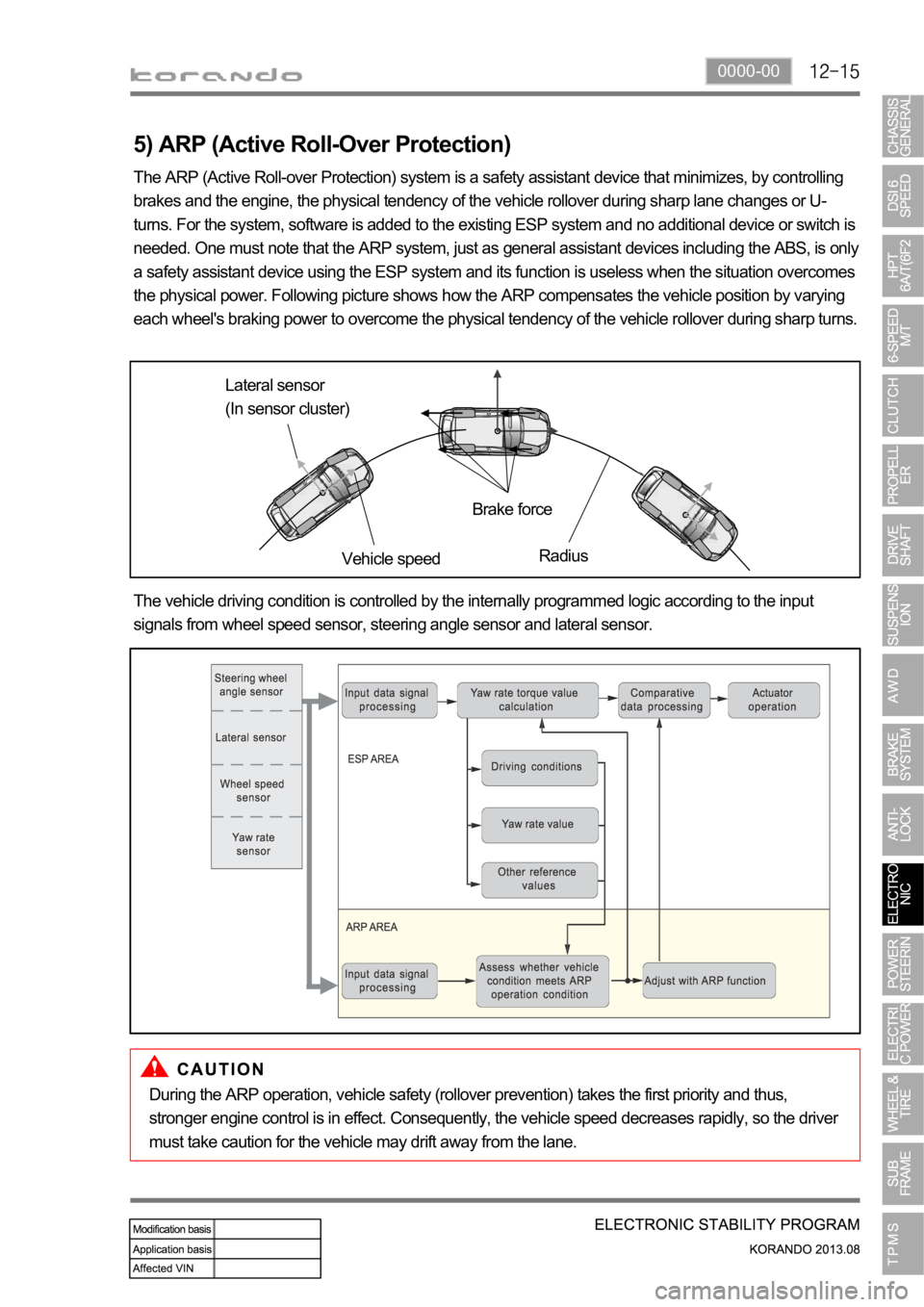
the physical power. Following picture shows how the ARP compensates the vehicle position by varying
each wheel's braking power to overcome the physical tendency of the vehicle rollover during sharp turns.
Lateral sensor
(In sensor cluster)
Vehicle speedBrake force
Radius
The vehicle driving condition is controlled by the internally programmed logic according to the input
signals from wheel speed sensor, steering angle sensor and lateral sensor.
During the ARP operation, vehicle safety (rollover prevention) takes the first priority and thus,
stronger engine control is in effect. Consequently, the vehicle speed decreases rapidly, so the driver
must take caution for the vehicle may drift away from the lane.
Page 1146 of 1336
2. TIGHTENING TORQUE
Item Tightening torque Remark
1. Power steering reservoir mounting bolt 8.8 to 13.7 Nm 12 mm x 2 EA
2. Power steering
pumpUpper mounting bolt/nut
13 mm x 1 EA
Lower mounting bolt
12 mm x 2 EA
3. Oil pipe Eye bolt (pump side) 53.9 to 63.7 Nm 22 mm
Steering gear box side nut 31.4 to 37.2 Nm 17 mm
4. Oil pipe bracket mounting nut 6.8 to 10.8 Nm 10 mm
5. Tie rod end lock nut 44.1 to 53.9 Nm 17 mm
6. Tie rod nut 63.7 to 78.4 Nm 22 mm
7. Lower shaft Lower mounting bolt
(gear box side)17.6 to 24.5 Nm 12 mm
Upper mounting bolt (column
side)17.6 to 24.5 Nm 12 mm
8. Column shaft Lower mounting bolt 19.6 to 24.5 Nm 12 mm
Upper mounting nut 19.6 to 24.5 Nm 12 mm
9. Steering wheel nut 39.2 to 49.1 Nm 22 mm
10. Loosened gear box mounting bolt/nut Left: 98.0 to 127.4 Nm 17 mm
Right: 88.3 to 107.9 Nm 17 mm
11. Heat shield mounting bolt 8.8 to 13.7 Nm 12 mm x 2 EA
Page 1147 of 1336
0000-00
3. DIFFERENCES BETWEEN HPS AND EPS
HPS EPS
1 Crankshaft pulley (DDU)
2 Auto tensioner
3 Tensioner pulley
4 Vacuum pump
5 A/C compressor pulley
6 Alternator pulley
7 Water pump pulley
8 No.1 idle pulley
9 No.2 idle pulley
10 Power steering pump -
HPS (Hydraulic Power Steering)EPS (Electric Power Steering)
Page 1148 of 1336

1. SYSTEM DESCRIPTION
The power steering has been designed to make the wheel move more easily than in a manual steering
system. The hydraulic power assists the process utilizing hydraulic fluid. The fluid increases pressure in
the power steering pump and aids the movement of the steering mechanism.
The power steering system consists of pump, oil reservoir, rack and gear box.
The power steering pump is a vane type and delivers hydraulic pressure to operate the power steering
system.
The pressure relief valve in the pump controls the discharging pressure.
The rotary valve in the rack and the pinion gear directs the oil from the power steering pump to one side
of the rack piston. The integrated rack piston converts the hydraulic pressure to linear movement. The
operating force of the rack moves the wheels through the tie rod, the tie rod end and the steering knuckle.
Even though the hydraulic pressure cannot be generated, a driver can steer the vehicle without power
assist but it needs very high steering force.
In this case, the operating force of the steering wheel is conveyed to the pinion, and the movement of the
pinion moves the rack through the pinion gear combined to the rack gear.