Page 1043 of 1336

3660-01
5. TRANSAXLE ELECTRONIC CONTROL SYSTEM
1) General Information
The transmission control unit (TCU) and its input/output network control the following transmission
operations:
Shift timing
Line pressure
Clutch pressure (shift feel)
Torque converter clutch -
-
-
-
also uses these signals when determining transaxle operating strategy. Using all of these input signals,
the TCU can determine when the time and conditions are right for a shift, or when to apply or release the
torque converter clutch. It will also determine the pressure needed to optimise shift feel.
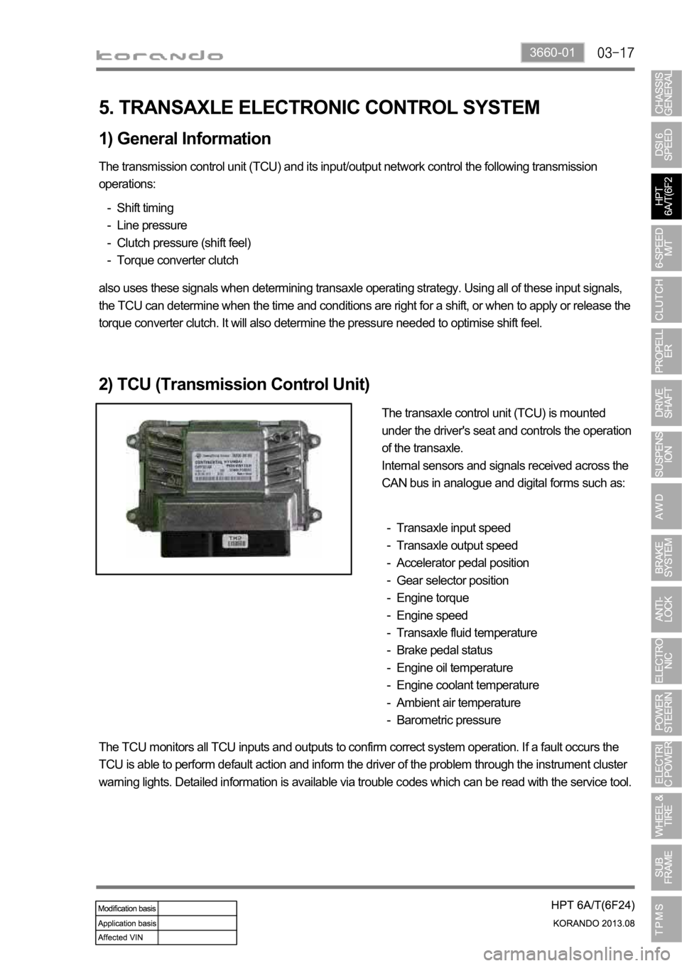
2) TCU (Transmission Control Unit)
The transaxle control unit (TCU) is mounted
under the driver's seat and controls the operation
of the transaxle.
Internal sensors and signals received across the
CAN bus in analogue and digital forms such as:
Transaxle input speed
Transaxle output speed
Accelerator pedal position
Gear selector position
Engine torque
Engine speed
Transaxle fluid temperature
Brake pedal status
Engine oil temperature
Engine coolant temperature
Ambient air temperature
Barometric pressure -
-
-
-
-
-
-
-
-
-
-
-
The TCU monitors all TCU inputs and outputs to confirm correct system operation. If a fault occurs the
TCU is able to perform default action and inform the driver of the problem through the instrument cluster
warning lights. Detailed information is available via trouble codes which can be read with the service tool.
Page 1089 of 1336
3) Parts Arrangement
Part nameVehicle with
CBSVehicle with ABS/EBDVehicle with
ESP
HECU
Not appliedAppliedApplied Front wheel speed sensor
Rear wheel speed sensor
ABS warning lamp
EBD indicator
Longitudinal G sensor 2WD: N/A, 4WD: Applied Not applied
Sensor cluster
(Yaw rate sensor,
lateral/longitudinal G sensor)
Not applied Applied
ESP indicator
ESP OFF switch and warning
lamp
Steering wheel angle sensor
Page 1090 of 1336
4850-00
A. Meter cluster-ABS, EBD, ESP
indicator/warning lampB. Master cylinder and
boosterC. HECU
F. Front/rear wheel speed sensor
Front/rear-4WD Rear-2WDH. Parking brakeG. Brake pedal
4) Component
ABS warning lamp
ESP indicator
D. Front brake
assembly
E. Rear brake
assembly
Disc
Disc
Parking brake
warning lamp
Caliper
Caliper
Page 1091 of 1336
2. SPECIFICATION (DSL ONLY)
Unit Description Specification
Front brake Type Ventilated disc
Outer diameter of disc
Inner diameter of caliper cylinder
Thickness of disc 26 mm (wear limit: 24 mm)
Thickness of brake pad 10.5 mm (wear limit: 2 mm)
Pad wear indicator Mechanical type
Rear brake Type Solid disc
Outer diameter of disc
Thickness of disc 10 mm (wear limit: 8.4 mm)
Thickness of brake pad 10 mm (wear limit: 2 mm)
Pad wear indicator Mechanical type
Brake booster Type Vacuum assist type
Size
Master cylinder Type Tandem (level sensor installed)
Inner diameter of cylinder
Brake pedal Maximum operating stroke
Pedal ratio 3.8 : 1
Free play 3 to 10 mm
Parking brake Type Mechanically expanded rear lining
Operating type Hand operated type
Inner diameter of drum
Brake oil Specification DOT 4
Capacity 0.7 to 0.8 liters
Service interval for brake fluid: Change every other year.
Page 1099 of 1336
4890-00
1. SPECIFICATION
Unit DescriptionSpecification
ABS ESP
HECUClock frequency 32 MHz 50 MHz
Memory 128 KB 512 KB
Switch Orifice Orifice
Wheel speed
sensorABS / ESP CBS
Operating temperature
Operating frequency 1 to 2,500 Hz 1 to 8,000 Hz
Operating voltage 4.5 to 16 V 3.3 to 18 V
G-sensor ABS CBS / ESP
Operating voltage 4.75 to 5.25 V N/A
Operating temperature
Operating range -1.5 to 1.5 g
Output voltage 0.5 to 4.5 V
Page 1100 of 1336
ABS / ESP CBS
Circuit diagram of wheel speed sensor
Page 1102 of 1336
3. G-sensor (for 4WD)
Located on the floor under
parking brake bracket in center
console.4. Rear wheel speed sensor
(for 2WD)
Located on knuckle. The
appearance is different from that
for 4WD.4. Wheel speed sensor
(for 4WD)
Located on knuckle. The
appearance of front sensor is
same with rear sensor.
2. ABS warning lamp
EBD warning lamp (ABS warning lamp +
Brake warning lamp)1. ABS hydraulic device and control unit
Located under the power steering fluid reservoir and
contains the pressure sensor.
2. COMPONENT
Page 1103 of 1336

4890-00
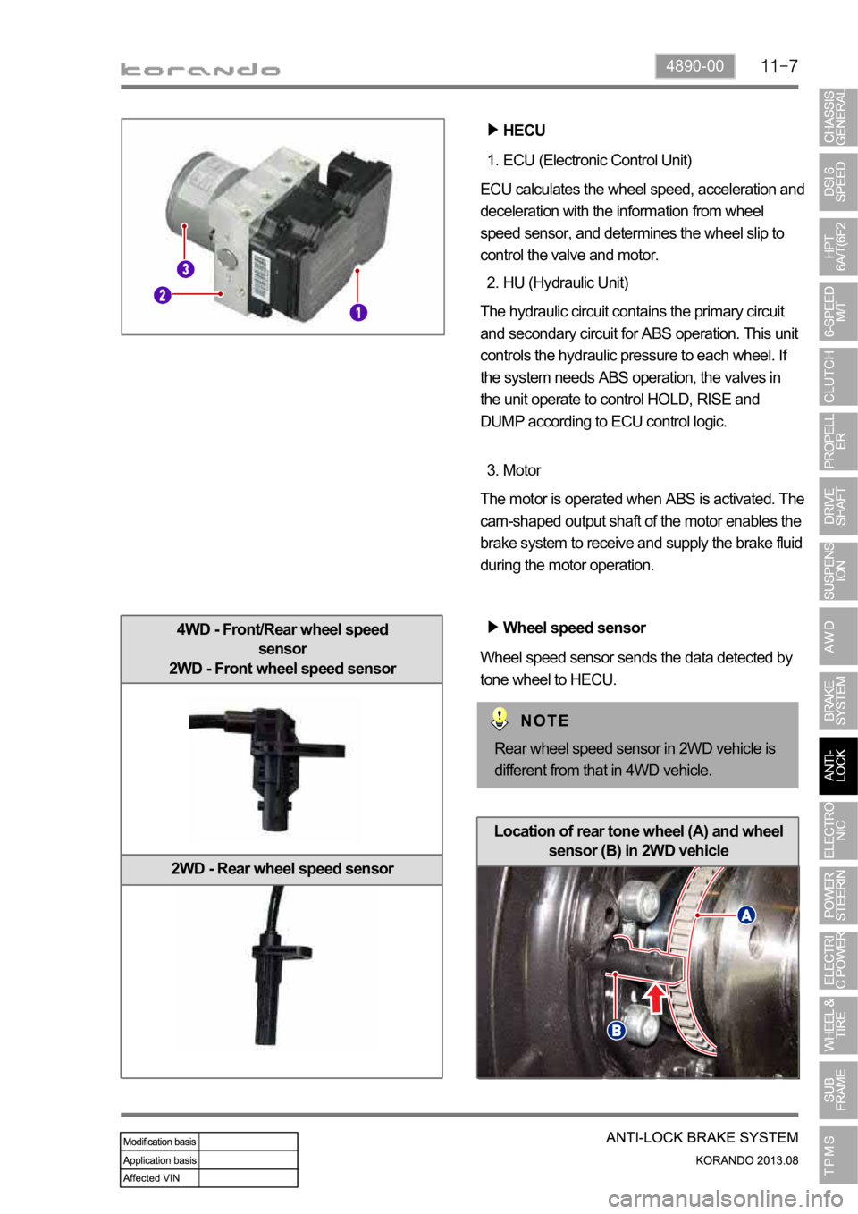
4WD - Front/Rear wheel speed
sensor
2WD - Front wheel speed sensor
2WD - Rear wheel speed sensor
ECU (Electronic Control Unit) 1.
ECU calculates the wheel speed, acceleration and
deceleration with the information from wheel
speed sensor, and determines the wheel slip to
control the valve and motor.
HU (Hydraulic Unit) 2.
The hydraulic circuit contains the primary circuit
and secondary circuit for ABS operation. This unit
controls the hydraulic pressure to each wheel. If
the system needs ABS operation, the valves in
the unit operate to control HOLD, RISE and
DUMP according to ECU control logic.
Motor 3.
The motor is operated when ABS is activated. The
cam-shaped output shaft of the motor enables the
brake system to receive and supply the brake fluid
during the motor operation.
Wheel speed sensor
Wheel speed sensor sends the data detected by
tone wheel to HECU.
HECU
Rear wheel speed sensor in 2WD vehicle is
different from that in 4WD vehicle.
Location of rear tone wheel (A) and wheel
sensor (B) in 2WD vehicle