Page 1150 of 1336
4610-00
1. SPECIFICATION
Unit Description Specification
System operationOperating type Motor driven power steering system
Operating temperature
Rated voltage 12 V
Rated current 85 A
Operating voltageNetwork 8 to 16 V
C-EPS ECU 8 to 16 V
Full Performance 10 to 16 V
MotorType 3-Phase BLAC (Brushless AC)
Rated current/voltage 85 A / 12 V (at idle 0.5 A)
Position sensor type Hall sensor type
Torque & angle sensorType Non-contact type
Steering columnOperating type Manual tilting & telescoping
Lower shaftType Sliding (Ball slip) type
Steering gearGear ratio 50.7 mm/rev
Rack stroke 145 mm
Maximum steering angleInner wheel
Outer wheel
Page 1153 of 1336

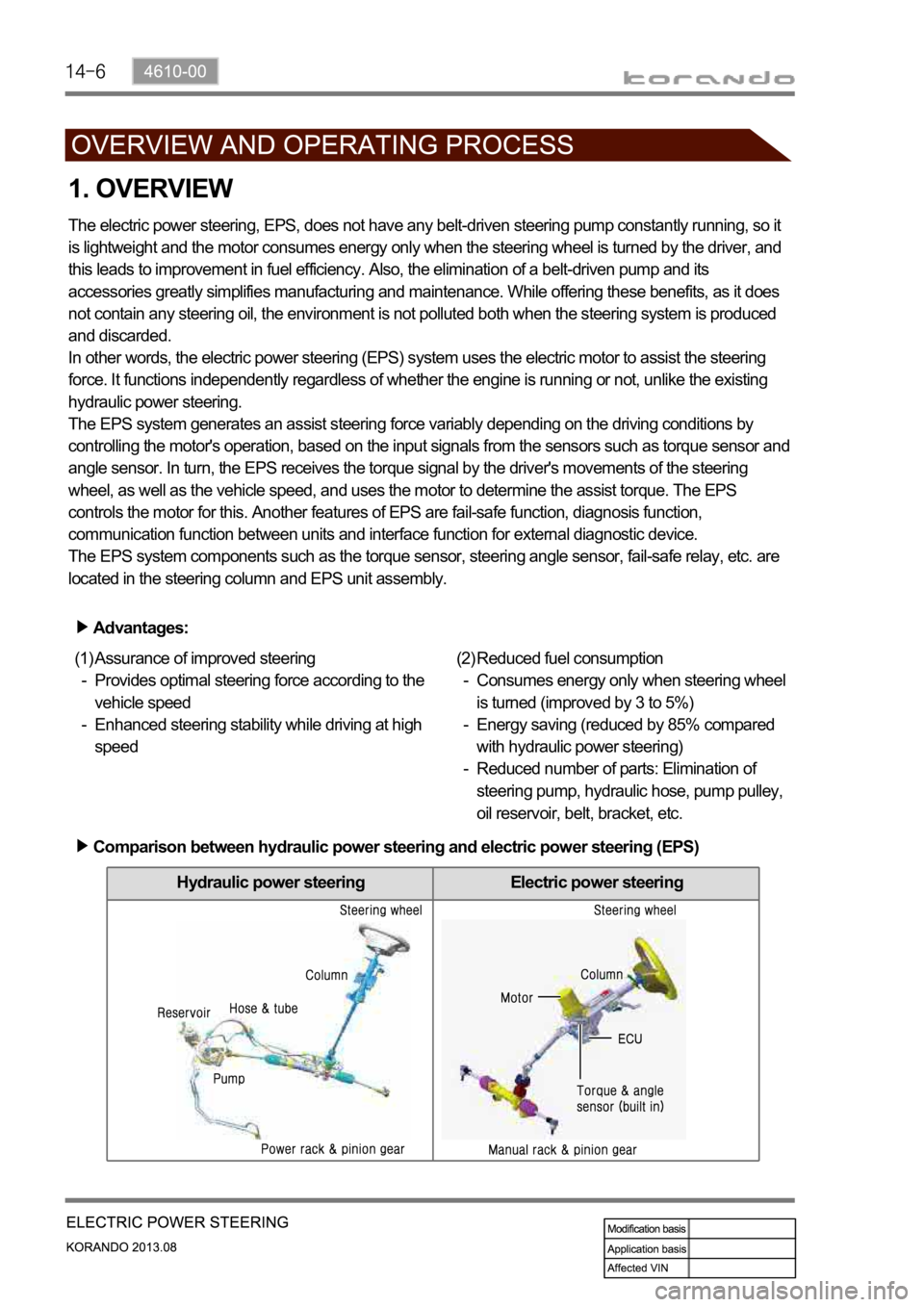
Hydraulic power steering Electric power steering
1. OVERVIEW
The electric power steering, EPS, does not have any belt-driven steering pump constantly running, so it
is lightweight and the motor consumes energy only when the steering wheel is turned by the driver, and
this leads to improvement in fuel efficiency. Also, the elimination of a belt-driven pump and its
accessories greatly simplifies manufacturing and maintenance. While offering these benefits, as it does
not contain any steering oil, the environment is not polluted both when the steering system is produced
and discarded.
In other words, the electric power steering (EPS) system uses the electric motor to assist the steering
force. It functions independently regardless of whether the engine is running or not, unlike the existing
hydraulic power steering.
The EPS system generates an assist steering force variably depending on the driving conditions by
controlling the motor's operation, based on the input signals from the sensors such as torque sensor and
angle sensor. In turn, the EPS receives the torque signal by the driver's movements of the steering
wheel, as well as the vehicle speed, and uses the motor to determine the assist torque. The EPS
controls the motor for this. Another features of EPS are fail-safe function, diagnosis function,
communication function between units and interface function for external diagnostic device.
The EPS system components such as the torque sensor, steering angle sensor, fail-safe relay, etc. are
located in the steering column and EPS unit assembly.
Advantages:
Assurance of improved steering
Provides optimal steering force according to the
vehicle speed
Enhanced steering stability while driving at high
speed (1)
-
-Reduced fuel consumption
Consumes energy only when steering wheel
is turned (improved by 3 to 5%)
Energy saving (reduced by 85% compared
with hydraulic power steering)
Reduced number of parts: Elimination of
steering pump, hydraulic hose, pump pulley,
oil reservoir, belt, bracket, etc. (2)
-
-
-
Comparison between hydraulic power steering and electric power steering (EPS)
Page 1154 of 1336
4610-00
2. OPERATION
When the driver turns the steering wheel, a torque is generated and the torque sensor and the steering
angle sensor in the EPS system detect the rotation of the steering column to run the electric motor. At
this time, the worm gear connected to the motor drives the helical gear mounted to the steering column
to generate the assist torque for the steering column. This allows the driver to operate the steering wheel
easier.Output torque = 1) Steering force (manual torque) + 2) Assist torque
Page 1181 of 1336

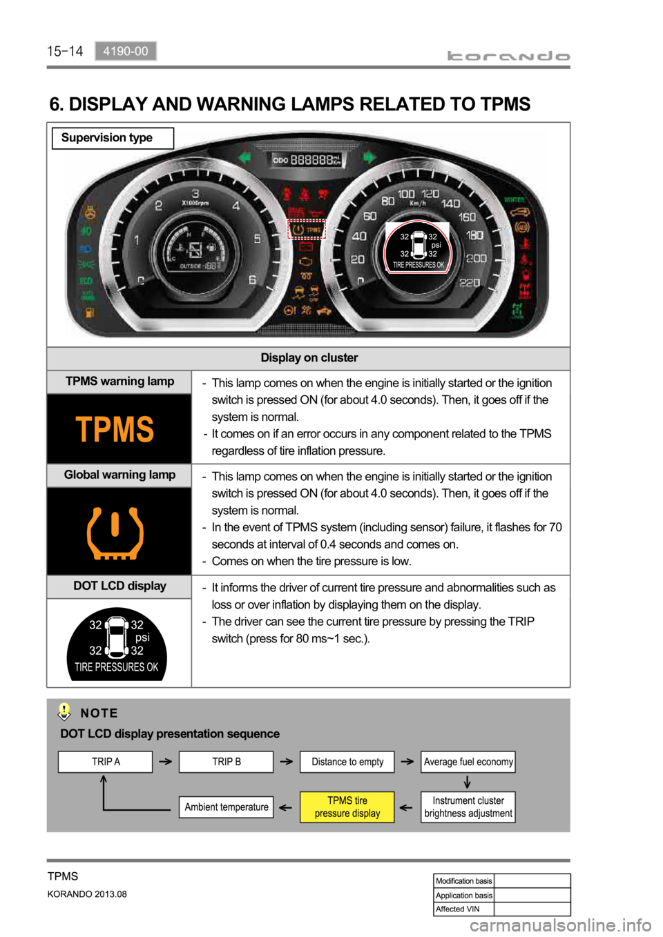
Display on cluster
TPMS warning lamp
Global warning lamp
DOT LCD display
6. DISPLAY AND WARNING LAMPS RELATED TO TPMS
This lamp comes on when the engine is initially started or the ignition
switch is pressed ON (for about 4.0 seconds). Then, it goes off if the
system is normal.
It comes on if an error occurs in any component related to the TPMS
regardless of tire inflation pressure. -
-
This lamp comes on when the engine is initially started or the ignition
switch is pressed ON (for about 4.0 seconds). Then, it goes off if the
system is normal.
In the event of TPMS system (including sensor) failure, it flashes for 70
seconds at interval of 0.4 seconds and comes on.
Comes on when the tire pressure is low. -
-
-
It informs the driver of current tire pressure and abnormalities such as
loss or over inflation by displaying them on the display.
The driver can see the current tire pressure by pressing the TRIP
switch (press for 80 ms~1 sec.). -
-
DOT LCD display presentation sequence
Supervision type
Page 1182 of 1336
4190-00
Display on cluster
TPMS warning lamp
Global warning lamp
DOT display
This lamp comes on when the engine is initially started or the ignition
switch is pressed ON (for about 4.0 seconds). Then, it goes off if the
system is normal.
It comes on if an error occurs in any component related to the TPMS
regardless of tire inflation pressure. -
-
This lamp comes on when the engine is initially started or the ignition
switch is pressed ON (for about 4.0 seconds). Then, it goes off if the
system is normal.
In the event of TPMS system (including sensor) failure, it flashes for 70
seconds at interval of 0.4 seconds and comes on.
Comes on when the tire pressure is low. -
-
-
The tire pressure for front wheels is displayed on the LCD display. The
tire pressure for rear wheels is displayed when pressing the Trip switch. -
Standard type
DOT display presentation sequence
Page 1192 of 1336
1. OVERVIEW
The climate system in the vehicle is an air regulating system which keeps the indoor air pleasant through
the heating, ventilation and air conditioning systems. The air conditioning systems fall in to two
categories; FATC (Full Automatic Temperature Control), which is a temperature control device which
receives signals from various sensors (ambient temperature sensor, water temperature sensor, sun-
load sensor, AMP sensor) and control switches to control the blower motor and all kinds of actuator
(mode door actuator, mix door actuator, air source door actuator) through MICOM in the FATC,
therefore, the interior temperature of the vehicle is kept to the temperature which is set by a driver and
MTC (Manual Temperature Control), which controls all the actuator and blower motor by the driver.
Page 1194 of 1336
2. LAYOUT
1) Exterior Layout
Liquid and suction pipe
The high/low-pressure A/C refrigerant flows
through this pipe. It is fitted with the refrigerant
pressure sensor.
Electric fan
It cools down the A/C condenser to speed up the
compression for the refrigerant in the condenser.
Refrigerant pressure sensor
It is mounted to the latter part of the right
headlamp. It converts the A/C refrigerant pressure
to voltage value and sends it to the engine ECU.
A/C compressor
It is installed to the left side of the engine
assembly, compresses the low-temperature and
low-pressure coolant and converts it to the high-
temperature and high-pressure coolant. Then, it
sends the coolant to the A/C condenser.
Page 1195 of 1336
6810-00
A/C condenser & receiver drier
It is installed in front of vehicle and condenses vapor
refrigerant into low temperature and high pressure liquid
refrigerant. The receiver drier is built in it.Ambient temperature sensor
It is mounted to the front section of the
vehicle and detects the ambient
temperature to send the voltage value
according to the resistance change to
the heater and A/C control assembly.
Engine ECU
It controls the A/C compressor, electric fan
and PTC heater according to the signal from
the A/C control panel.
Expansion valve
It is mounted to the inlet of the evaporator
core and supplies the appropriate quantity
of refrigerant to the evaporator.
Integrated receiver drier