Page 554 of 1336
8530-00
5) ECO Cruise Control
ECO cruise is ready and ECO cruise indicator on the instrument cluster comes on when pushing down
the cruise control lever. To activate the ECO cruise mode, push down the cruise control lever again. To
cancel the ECO cruise mode while in operation, push down the cruise control lever again. The ECO
cruise mode is canceled and the indicator goes out.
What is ECO Cruise mode?
In this mode, the smooth acceleration to the set cruise speed can be achieved by optimized fuel
consumption.
Page 563 of 1336

1490-00
3. ECU CONTROL
1) Functions
ECU receives and analyzes signals from various sensors and then modifies those signals into
permissible voltage levels and analyzes to control respective actuators.
ECU microprocessor calculates injection period and injection timing proper for engine piston speed and
crankshaft angle based on input data and stored specific map to control the engine power and emission
gas.
Output signal of the ECU microprocessor activates the injector solenoid valve to control the fuel injection
period and injection timing; so controls various actuators in response to engine changes.
Auxiliary function of ECU has adopted to reduce emission gas, improve fuel economy and enhance
safety, comforts and conveniences. For example, there are autocruise and immobilizer and adopted
CAN communication to exchange data among electrical systems (automatic T/M and brake system) in
the vehicle fluently. And the diagnostic tool can be used to diagnose vehicle status and defectives.
water and electromagnetism and there should be no mechanical shocks.
2) Control Functions
Controls by operating stages:
To make optimum combustion under every operating stage, ECU should calculate proper injection
volume in each stage by considering various factors.
Starting injection volume control:
During initial starting, injecting fuel volume will be calculated by function of temperature and engine
cranking speed. Starting injection continues from when the ignition switch is turned to ignition
position to till the engine reaches to allowable minimum speed.
Driving mode control:
If the vehicle runs normally, fuel injection volume will be calculated by accelerator pedal travel and
engine rpm and the drive map will be used to match the drivers inputs with optimum engine power. -
-
-
Page 569 of 1336

0000-00
(4) Features
Determines the ignition timing according to input signal
The ECU always analyzes the following elements when determining the ignition timing. 1.
Crankshaft position sensor
Camshaft position sensor
Coolant temperature sensor
Intake air temperature/air mass -
-
-
-
Warm-up of catalytic converter
The ignition timing is retarded for about 20 seconds to operate the catalytic converter according to the
operating temperature under the following conditions: 2.
The idle speed is increased by the idle speed control to help warming up of the catalytic converter -
-
Idle speed control
The ignition timing control can be performed faster than the control through the throttle valve.
Fuel cut-off in deceleration
The ignition timing is retarded temporarily to prevent abrupt increase of the torque when the
combustion is restarted.
Intake air temperature/coolant temperature
The ignition timing is retarded to prevent knocking if the intake air temperature or coolant temperature
is high. The ignition timing is retarded in the following cases. 3.
4.
5.
-
-
The ignition timing retard for intake air temperature and for coolant temperature is added up for
correction.
ESP/ASR control mode
The ignition timing is retarded to reduce engine torque as fast as possible under the ESP/ASR
control mode.
Knocking control
If knocking occurs in the cylinder, the ignition angle of the corresponding cylinder is retarded. The
6.
7.
Page 571 of 1336

0000-00
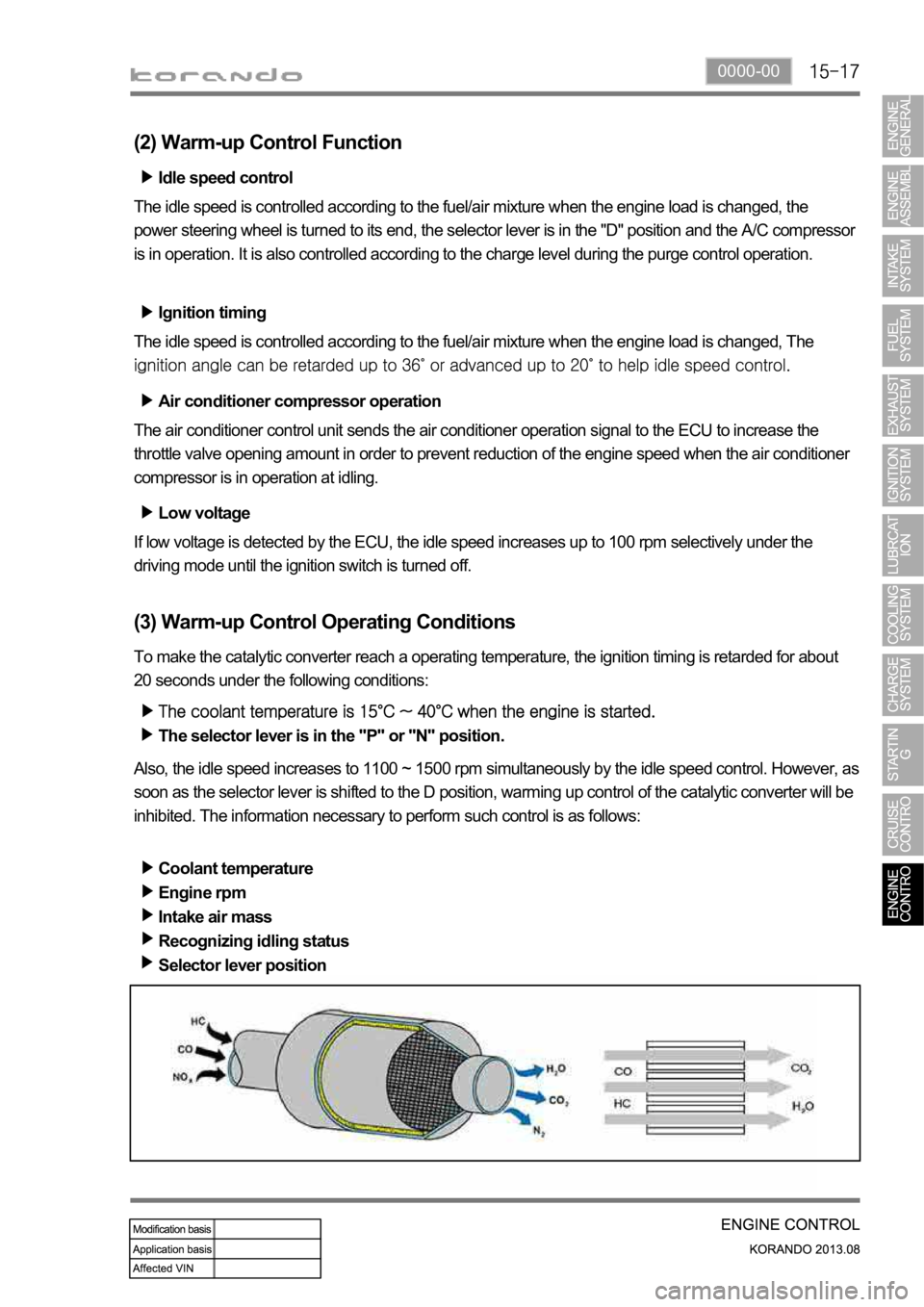
(2) Warm-up Control Function
Low voltage
If low voltage is detected by the ECU, the idle speed increases up to 100 rpm selectively under the
driving mode until the ignition switch is turned off. Idle speed control
The idle speed is controlled according to the fuel/air mixture when the engine load is changed, the
power steering wheel is turned to its end, the selector lever is in the "D" position and the A/C compresso
r
is in operation. It is also controlled according to the charge level during the purge control operation.
Ignition timing
The idle speed is controlled according to the fuel/air mixture when the engine load is changed, The
Air conditioner compressor operation
The air conditioner control unit sends the air conditioner operation signal to the ECU to increase the
throttle valve opening amount in order to prevent reduction of the engine speed when the air conditioner
compressor is in operation at idling.
(3) Warm-up Control Operating Conditions
To make the catalytic converter reach a operating temperature, the ignition timing is retarded for about
20 seconds under the following conditions:
The selector lever is in the "P" or "N" position.
Also, the idle speed increases to 1100 ~ 1500 rpm simultaneously by the idle speed control. However, as
soon as the selector lever is shifted to the D position, warming up control of the catalytic converter will be
inhibited. The information necessary to perform such control is as follows:
Coolant temperature
Engine rpm
Intake air mass
Recognizing idling status
Selector lever position
Page 611 of 1336
0000-00
2. OPERATING PROCESS
System diagram
Operation
EEM monitors the electric loads and battery conditions and controls the voltage to improve the fuel
economy and battery charging efficiency.
SOC) to engine ECU with LIN communication.
Engine ECU outputs the information from EBS and regulating control signal (PWM) according to the
Engine ECU controls the magnetic resistance between stator coil and rotor coil by controlling the
current in rotor coil according to PWM duty value.
The alternating voltage induced to stator coil is converted to direct voltage by rectifier. And, EBS
-
-
-
-
-
Page 612 of 1336
Operation of charge warning lamp
ECU checks the generating voltage from alternator and circuit conditions and sends the warning lamp ON
signal to meter cluster through CAN line.Basic control logic according to the driving conditions
Engine ECU determines the engine loads according to the fuel injection volume and engine speed. It
charges the battery by increasing the generating voltage during deceleration. To improve the fuel
economy by reducing the alternator load during acceleration, engine ECU decreases the generating
voltage and consumes the battery voltage.
Page 632 of 1336
3. MAJOR CHANGES
Changes for engine compartment fuse box
8410-02 Engine compartment fuse box
- Changed layout
Name Changes made
A ALT terminal and fuse (150A) Newly adopted
B A/C compressor relay Changed to PCB type
C Headlamp high beam Changed to PCB type
D Rear glass/heated mirror relay Changed to PCB type
E Cooling fan high-speed relay Changed to Micro type
F Blower motor relay Changed to Micro type
G Cooling fan low-speed relay Changed to Micro type
H Cooling fan relay Changed to Micro type
I Fuel heater relay Changed to Micro type
J PTC1 heater relay Changed to Micro type
K Power window relay Changed to Micro type
L Starting relay Changed to Micro type
Page 791 of 1336
8010-01
Status Supervision type
LCD display
The ESCL (Electric Steering Column Lock) is a device to lock the steering handle
using an electric signal, not a mechanical type and shows the messages above if the
relevant systems are faulty.
4) ESCL
5) LCD display
Status Old New
LCD display
Bar graph border maintained when adjusting illumination brightness
Average fuel economy and instant fuel economy displayed simultaneously
-
Auto cruise indicator and supervision cluster DOT LCD graphic added for gasoline
engine ? newly adopted ?
-
DOT LCD winter mode deleted