Page 1128 of 1336

0000-00
2) Operation of ESP System
The ESP (Electronic Stability Program) has been developed to help a driver avoid danger of losing
control of the vehicle stability due to understeer or oversteer during cornering. The yaw rate sensor,
lateral sensor and longitudinal sensor in the sensor cluster and the steering wheel angle sensor under
the steering column detect the vehicle conditions when the inner or outer wheels are spinning during
oversteer, understeer or cornering. The ESP ECU controls against oversteer or understeer during
cornering by controlling the vehicle stability using input values from these sensors and applying the
braking force to the corresponding wheels independently. The system also controls the engine power
right before the wheel spin synchronized with the ASR function to decelerate the vehicle automatically in
order to maintain the vehicle stable during cornering.
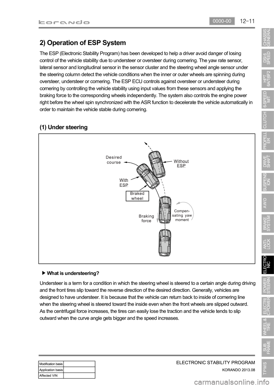
(1) Under steering
What is understeering?
Understeer is a term for a condition in which the steering wheel is steered to a certain angle during driving
and the front tires slip toward the reverse direction of the desired direction. Generally, vehicles are
designed to have understeer. It is because that the vehicle can return back to inside of cornering line
when the steering wheel is steered toward the inside even when the front wheels are slipped outward.
As the centrifugal force increases, the tires can easily lose the traction and the vehicle tends to slip
outward when the curve angle gets bigger and the speed increases.
Page 1132 of 1336

0000-00
5) ARP (Active Roll-Over Protection)
The ARP (Active Roll-over Protection) system is a safety assistant device that minimizes, by controlling
brakes and the engine, the physical tendency of the vehicle rollover during sharp lane changes or U-
turns. For the system, software is added to the existing ESP system and no additional device or switch is
needed. One must note that the ARP system, just as general assistant devices including the ABS, is only
a safety assistant device using the ESP system and its function is useless when the situation overcomes
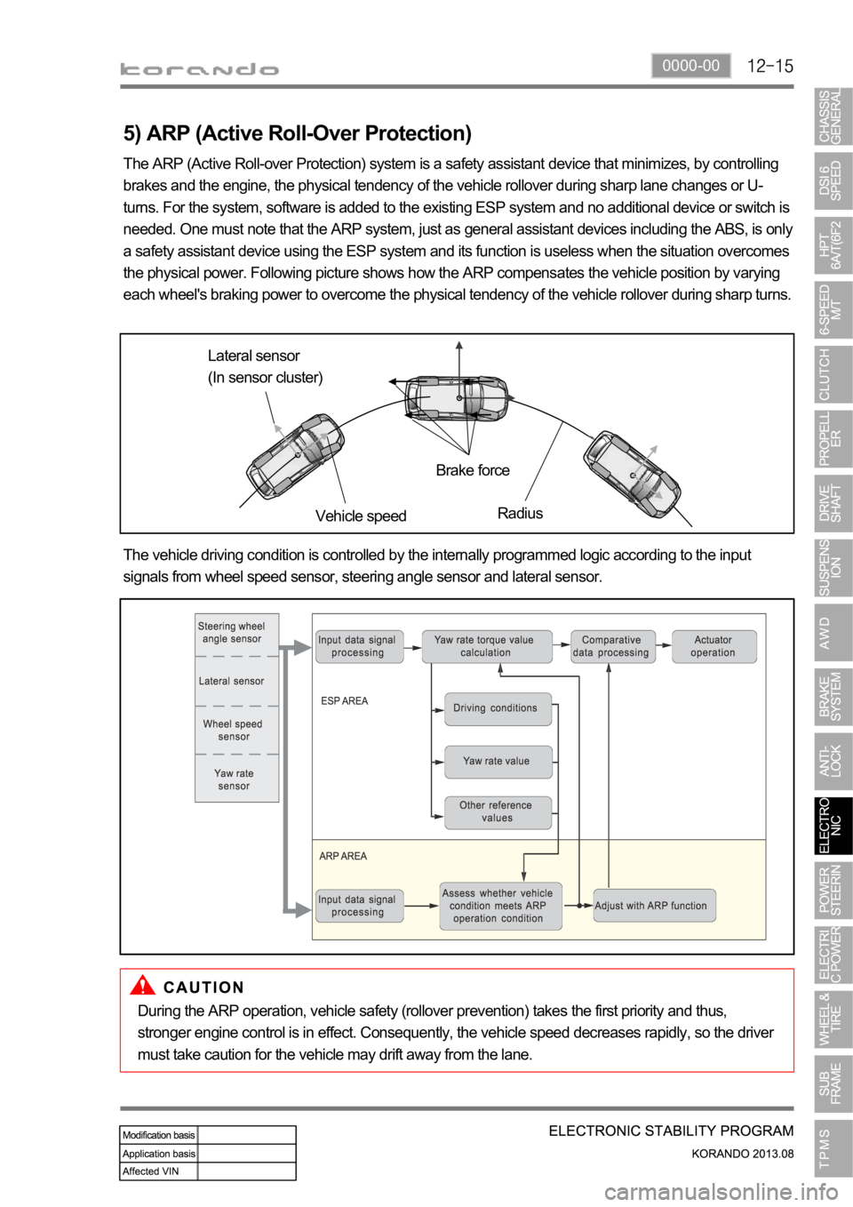
the physical power. Following picture shows how the ARP compensates the vehicle position by varying
each wheel's braking power to overcome the physical tendency of the vehicle rollover during sharp turns.
Lateral sensor
(In sensor cluster)
Vehicle speedBrake force
Radius
The vehicle driving condition is controlled by the internally programmed logic according to the input
signals from wheel speed sensor, steering angle sensor and lateral sensor.
During the ARP operation, vehicle safety (rollover prevention) takes the first priority and thus,
stronger engine control is in effect. Consequently, the vehicle speed decreases rapidly, so the driver
must take caution for the vehicle may drift away from the lane.
Page 1172 of 1336

4190-00
3. CAUTIONS
The tire pressure values displayed on the instrument cluster are sent from the wheel modules after
the vehicle is driven for a period of time. Therefore, they are not displayed at initial start (more than
20 minutes have elapsed after ignition off). It can be displayed after 10 minutes of driving at speed of
20 km/h or higher. -
The TPMS uses a radio frequency and a high frequency band between the wheel module and the
TPMS ECU for communication.
Therefore, if the vehicle is equipped with the electronic equipment such as mobile camera monitor
or the vehicle is passing through the area with a strong electromagnetic field, the system may not
operate normally.
For the vehicle equipped with the TPMS, the TPMS warning lamp on the instrument cluster comes
on and pressure values on the EL display is displayed as bars (--) after driving for a certain period of
time if a newly installed tire is not equipped with the wheel module. -
-
At initial startDisplay pressure value after
detecting
position automatically
Standard type
Supervision type
Page 1175 of 1336
Instrument cluster display related to TPMS (with standard)
DOT LCD display TPMS warning lamp Global warning lamp
2. LAYOUT 1. OVERVIEW
The TPMS is used to reduce the accident rate, enhance driving stability and avoid an unnecessary fuel
consumption and tire wear by monitoring the tire pressure and temperature to inform the driver of tire
pressure information and its status through the instrument cluster. The wheel module fitted in the tire
transmits the internal data for the tire to the TPMS ECU periodically through the wireless transmission.
The TPMS ECU can detect the positions of the wheel modules fitted to each wheel automatically and
sends the signal on tire condition through the CAN line to the instrument cluster so that the driver can
identify the wheel module in question.
Instrument cluster display related to TPMS (with supervision)
DOT LCD display TPMS warning lamp Global warning lamp
Page 1178 of 1336

4190-00
4. TPMS PRESSURE VALUE DISPLAYING PROCESS
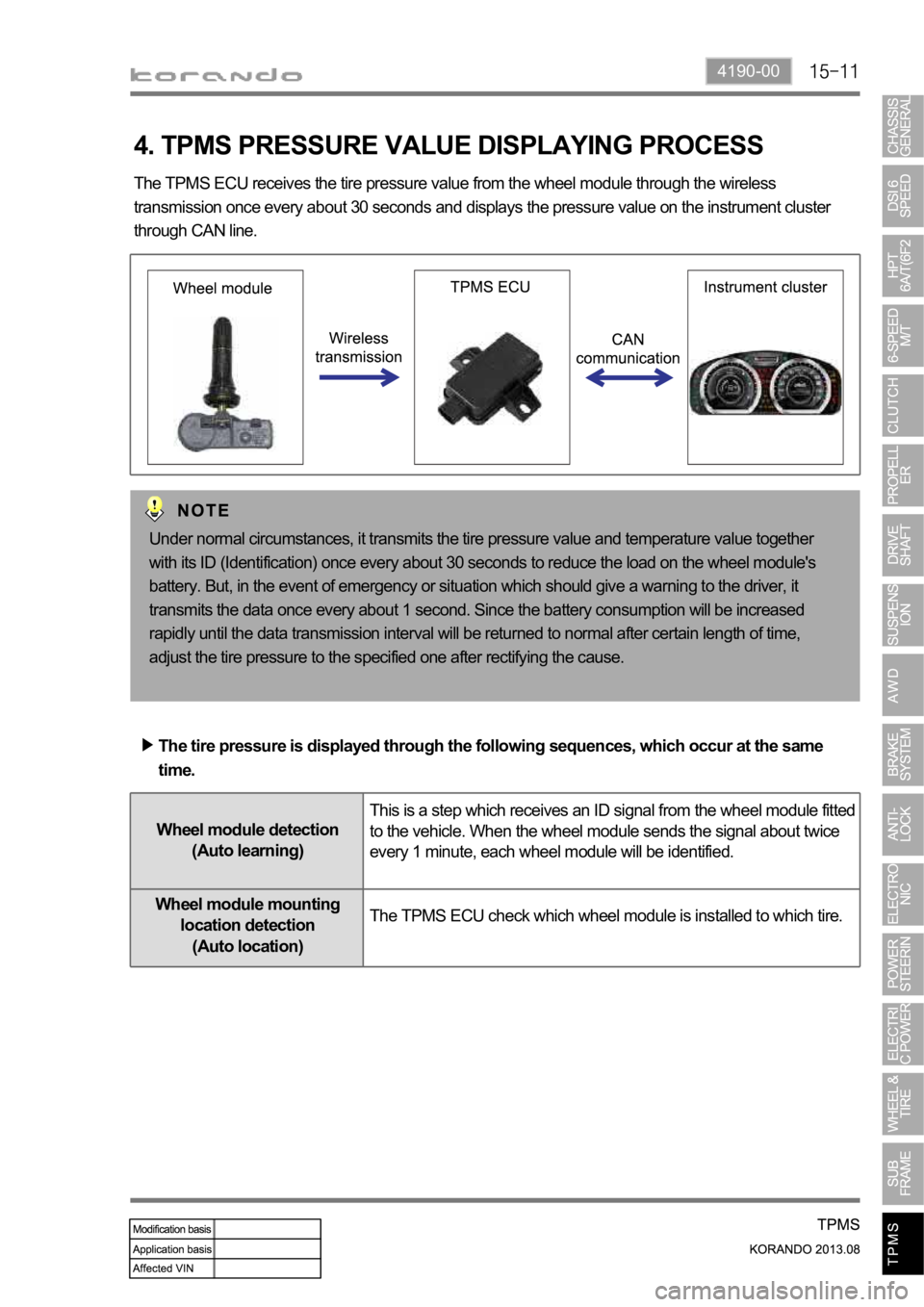
The TPMS ECU receives the tire pressure value from the wheel module through the wireless
transmission once every about 30 seconds and displays the pressure value on the instrument cluster
through CAN line.
Under normal circumstances, it transmits the tire pressure value and temperature value together
with its ID (Identification) once every about 30 seconds to reduce the load on the wheel module's
battery. But, in the event of emergency or situation which should give a warning to the driver, it
transmits the data once every about 1 second. Since the battery consumption will be increased
rapidly until the data transmission interval will be returned to normal after certain length of time,
adjust the tire pressure to the specified one after rectifying the cause.
The tire pressure is displayed through the following sequences, which occur at the same
time.
Wheel module detection
(Auto learning)This is a step which receives an ID signal from the wheel module fitted
to the vehicle. When the wheel module sends the signal about twice
every 1 minute, each wheel module will be identified.
Wheel module mounting
location detection
(Auto location)The TPMS ECU check which wheel module is installed to which tire.
Page 1179 of 1336
5. LOW TIRE PRESSURE WARNING
If the tire pressure is less than 13% of the proper value calculated by the TPMS ECU depending on the
ambient temperature for more than 8 minutes, the 1st low tire pressure warning is given. And, if the tire
pressure is less than 20% for more than 4 minutes, the 2nd warning is given. At this time, the "Check
tire" message is displayed on the DOT LCD display and the global warning lamp comes on.
ECU receives the ambient temperature signal from the instrument cluster through CAN
communication and calculates the proper tire pressure to correct it since the tire pressure changes
depending on the ambient temperature.
Page 1181 of 1336

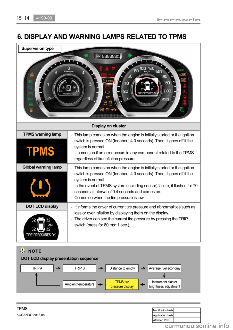
Display on cluster
TPMS warning lamp
Global warning lamp
DOT LCD display
6. DISPLAY AND WARNING LAMPS RELATED TO TPMS
This lamp comes on when the engine is initially started or the ignition
switch is pressed ON (for about 4.0 seconds). Then, it goes off if the
system is normal.
It comes on if an error occurs in any component related to the TPMS
regardless of tire inflation pressure. -
-
This lamp comes on when the engine is initially started or the ignition
switch is pressed ON (for about 4.0 seconds). Then, it goes off if the
system is normal.
In the event of TPMS system (including sensor) failure, it flashes for 70
seconds at interval of 0.4 seconds and comes on.
Comes on when the tire pressure is low. -
-
-
It informs the driver of current tire pressure and abnormalities such as
loss or over inflation by displaying them on the display.
The driver can see the current tire pressure by pressing the TRIP
switch (press for 80 ms~1 sec.). -
-
DOT LCD display presentation sequence
Supervision type
Page 1182 of 1336
4190-00
Display on cluster
TPMS warning lamp
Global warning lamp
DOT display
This lamp comes on when the engine is initially started or the ignition
switch is pressed ON (for about 4.0 seconds). Then, it goes off if the
system is normal.
It comes on if an error occurs in any component related to the TPMS
regardless of tire inflation pressure. -
-
This lamp comes on when the engine is initially started or the ignition
switch is pressed ON (for about 4.0 seconds). Then, it goes off if the
system is normal.
In the event of TPMS system (including sensor) failure, it flashes for 70
seconds at interval of 0.4 seconds and comes on.
Comes on when the tire pressure is low. -
-
-
The tire pressure for front wheels is displayed on the LCD display. The
tire pressure for rear wheels is displayed when pressing the Trip switch. -
Standard type
DOT display presentation sequence