Page 1184 of 1336
4190-00
Standard type
Status Operating conditions Display
Tire pressure
displayAt initial start (more than 20 minutes have
elapsed after ignition off), the tire pressure is
not determined. It can be displayed after 10
minutes of driving at speed of 20 km/h or
higher.
FR - display
RR - displayIf the tire pressure is abnormal when it is not
The standard type instrument cluster shows
Low tire pressure warning
If the tire pressure is less than 13% of the proper value for more than 8 minutes, the 1st low tire
pressure warning is given. And, if the tire pressure is less than 20% for more than 4 minutes, the
2nd warning is given. The message "Check tire" is displayed on the instrument cluster DOT LCD
display.
(see "LOW TIRE PRESSURE WARNING in this section)
Priority of TPMS warnings
The situation can occur in which two warning messages are displayed depending on the vehicle
condition. If this happen, the warning messages are displayed according to the priority below.
Page 1185 of 1336

7. TIRE INFLATION PROCEDURE FOR VEHICLE WITH TPMS
1) Overview
For the vehicle with TPMS, the tire should be inflated in a method different from the conventional method
since the tire pressure values displayed on the tire pressure gauge and instrument cluster are different
after inflation.
The tire pressure displayed on the instrument cluster should be checked after a certain time delay
(wireless transmission time for wheel module).
The displayed value can be changed after driving even if it was set to the specified value.
2) Tire Inflation Procedure
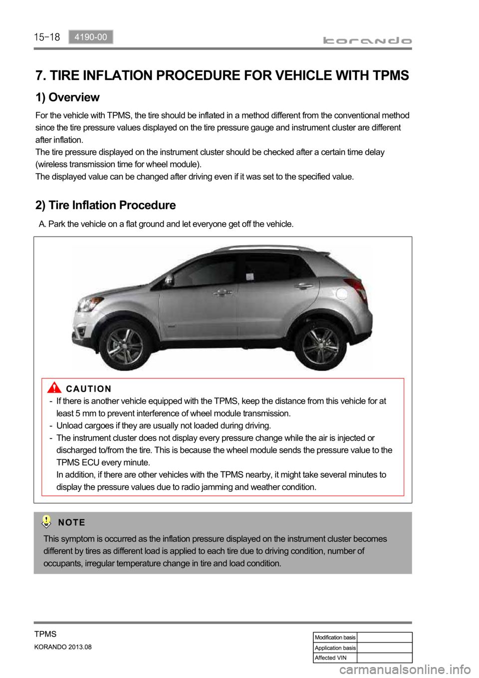
Park the vehicle on a flat ground and let everyone get off the vehicle. A.
This symptom is occurred as the inflation pressure displayed on the instrument cluster becomes
different by tires as different load is applied to each tire due to driving condition, number of
occupants, irregular temperature change in tire and load condition.
If there is another vehicle equipped with the TPMS, keep the distance from this vehicle for at
least 5 mm to prevent interference of wheel module transmission.
Unload cargoes if they are usually not loaded during driving.
The instrument cluster does not display every pressure change while the air is injected or
discharged to/from the tire. This is because the wheel module sends the pressure value to the
TPMS ECU every minute.
In addition, if there are other vehicles with the TPMS nearby, it might take several minutes to
display the pressure values due to radio jamming and weather condition. -
-
-
Page 1186 of 1336
4190-00
Tire inflation procedure
Check tire pressure on instrument cluster
DOT LCD display
Normal tire pressure Improper tire pressure
Tire inflation & judgment B.
Fill the tire pressure (air) according to the tire inflation procedure. -
Fill specified tire pressure
(32 psi)
Drive vehicle at 20 km/h or higher
for less than 10 min.
If checking for the tire
shows it is normal, carry
out the work again
according to the tire
inflation procedure.
Finish
Not OK
OK
Supervision type
Standard type
Page 1232 of 1336

8810-00
1. AIR BAG SYSTEM OVERVIEW
The air bag system is divided into front air bag system and side air bag system. The system protects the
occupant's body by deploying the air bags in the event of a collision. The system consists of 8 inflators
including the inflators of the seat belt pretensioners, air bag unit (SDM), and 4 impact sensors on the
front side and both sides of the vehicle. The air bag unit (SDM) determines the operation of each air bag
module and seat belt pretensioners using the crash signals from the front and side impact sensors in the
event of a collision. The front and side air bag systems are operated independently, and the body control
module (BCM) activates the auto door unlock function and various lamps including hazard warning lamp
and room lamps, when the crash signal from the SDM is received to notify others of emergency situation
and let the occupant escape easily. The SDM is equipped with self diagnosis function, and it performs
the diagnosis on the internal/external devices of the air bag system for a certain period of time after IGN
ON. And it monitors the air bag system regularly and turns on the air bag warning lamp on the
instrument cluster when a fault is found in the system, to notify the driver. The SDM has event data
recorder (EDR) function that stores the driving information data transmitted through CAN communication
from various units (vehicle speeds, engine rpm, brake application, etc.) in a crash or near crash event,
when the acceleration sensor in the air bag unit detects a sharp acceleration change, regardless of the
air bag deployment
Page 1245 of 1336

4. AIR BAG SYSTEM SELF DIAGNOSIS
1) Air Bag Unit (SDM) Self Diagnosis
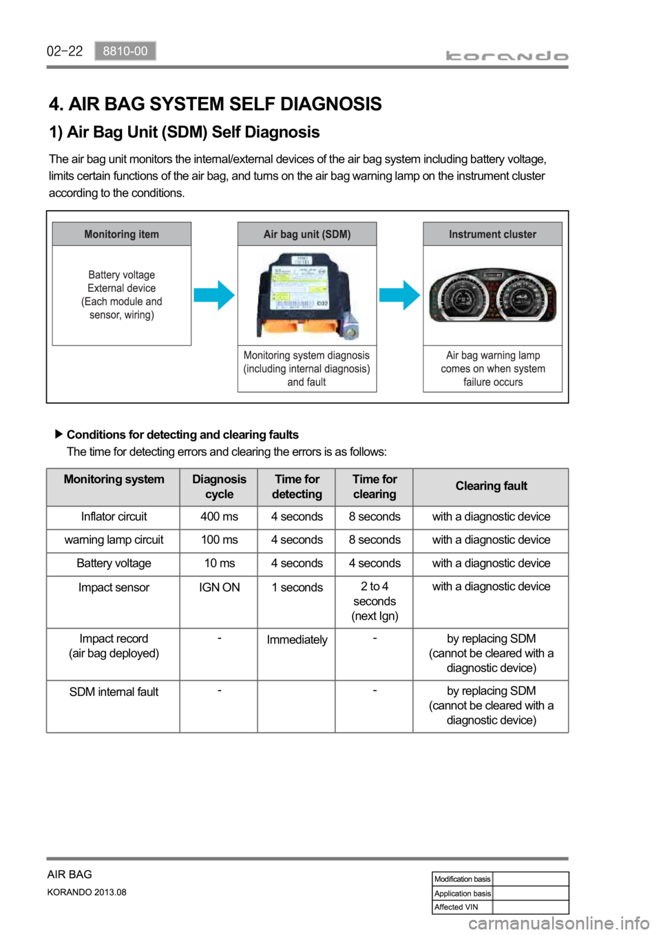
The air bag unit monitors the internal/external devices of the air bag system including battery voltage,
limits certain functions of the air bag, and turns on the air bag warning lamp on the instrument cluster
according to the conditions.
Conditions for detecting and clearing faults
The time for detecting errors and clearing the errors is as follows:
Monitoring system Diagnosis
cycleTime for
detectingTime for
clearingClearing fault
Inflator circuit 400 ms 4 seconds 8 seconds with a diagnostic device
warning lamp circuit 100 ms 4 seconds 8 seconds with a diagnostic device
Battery voltage 10 ms 4 seconds 4 seconds with a diagnostic device
Impact sensor IGN ON 1 seconds2 to 4
seconds
(next Ign)with a diagnostic device
Impact record
(air bag deployed)-
Immediately-
by replacing SDM
(cannot be cleared with a
diagnostic device)
SDM internal fault--
by replacing SDM
(cannot be cleared with a
diagnostic device)
Page 1246 of 1336
8810-00
Air bag warning lamp
2) Air Bag Warning Lamp
The air bag unit turns on the air bag warning lamp on the instrument cluster for 6 seconds after IGN ON
while performing self diagnosis for the air bag system. If no fault is found in the system, it turns off the
warning lamp. After this, the unit monitors the system regularly, and notifies the driver by turning on the
air bag warning lamp when a fault is found in the system.
System normal
Comes on for 6 seconds after IGN ON and then goes out.
The air bag warning lamp comes on when: *
diagnosis is performed for the inside/external devices of
the system when the ignition is turned on
the air bag system is malfunctioning
the air bag unit and a diagnostic equipment communicate
each other -
-
-
(1) Air bag warning lamp ON at initial IGN ON
Page 1299 of 1336

7340-00
3. SUNROOF OPEN WARNING
1) Warning Sound
When removing the key and then opening the door with the sunroof open, the warning sound is heard.
Closing the door stops the warning sound.
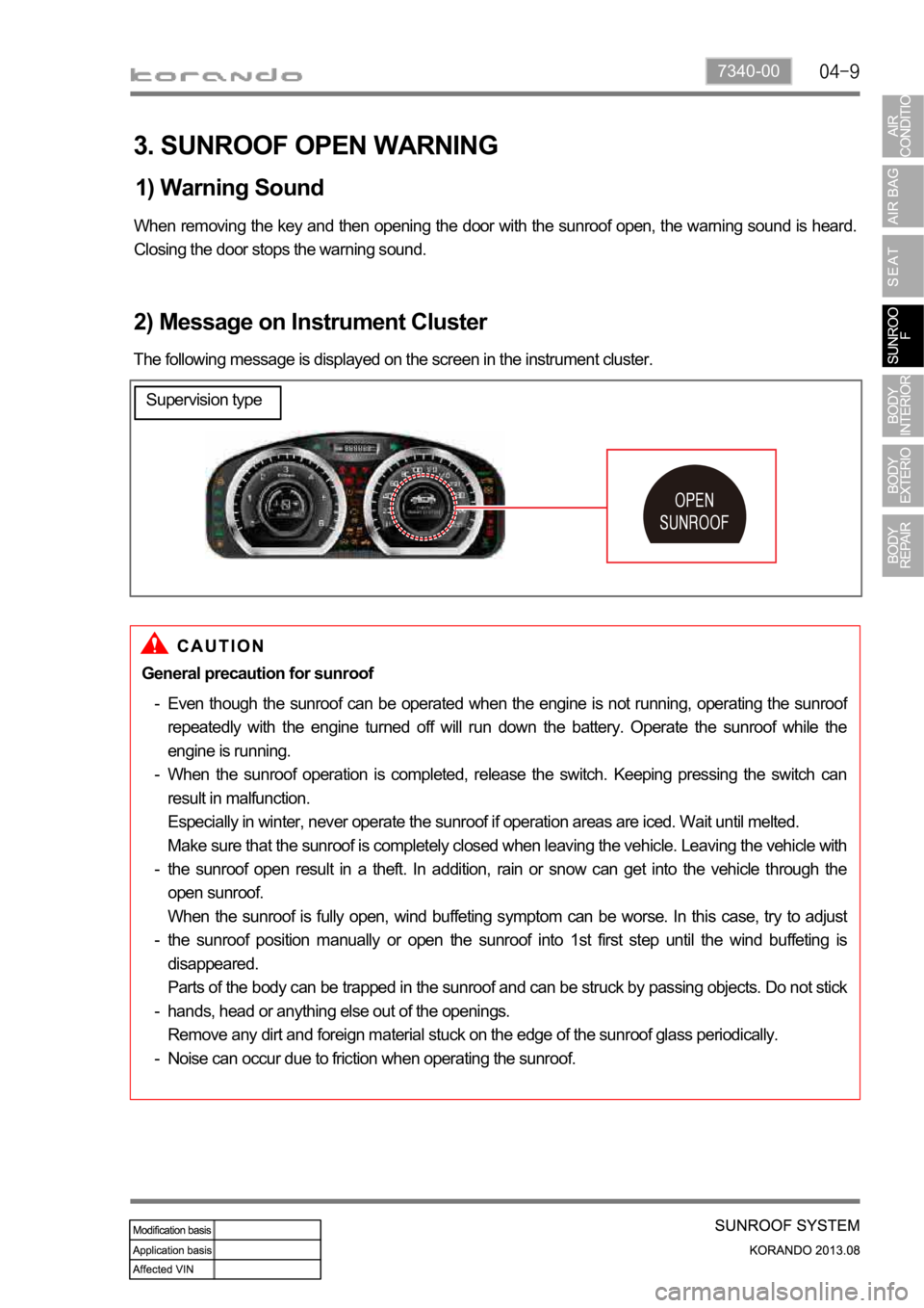
2) Message on Instrument Cluster
The following message is displayed on the screen in the instrument cluster.
General precaution for sunroof
Even though the sunroof can be operated when the engine is not running, operating the sunroo
f
repeatedly with the engine turned off will run down the battery. Operate the sunroof while the
engine is running.
When the sunroof operation is completed, release the switch. Keeping pressing the switch can
result in malfunction.
Especially in winter, never operate the sunroof if operation areas are iced. Wait until melted.
Make sure that the sunroof is completely closed when leaving the vehicle. Leaving the vehicle with
the sunroof open result in a theft. In addition, rain or snow can get into the vehicle through the
open sunroof.
When the sunroof is fully open, wind buffeting symptom can be worse. In this case, try to adjust
the sunroof position manually or open the sunroof into 1st first step until the wind buffeting is
disappeared.
Parts of the body can be trapped in the sunroof and can be struck by passing objects. Do not stick
hands, head or anything else out of the openings.
Remove any dirt and foreign material stuck on the edge of the sunroof glass periodically.
Noise can occur due to friction when operating the sunroof. -
-
-
-
-
-
Supervision type
Page 1301 of 1336
Cluster fascia panel
RH cluster fascia panel and molding have been newly applied.
Instrument panel
- The design and material of IP have been
changed.
- An invisible type passenger air bag
module has been applied.LH side fascia panel & molding
The design of LH side fascia panel & molding has
been changed.
1. MAJOR CHANGES
Instrument Panel
Cluster fascia molding
RH cluster
fascia panel