2013 SKODA ROOMSTER trailer
[x] Cancel search: trailerPage 123 of 219
The ball head is released in this position and falls freely into the hand. If it does
not fall freely into the hand, use your other hand to push it upwards.
At the same time, the ball head latches into the ready position and is thus readyto be re-inserted into the mounting recess »
.
›
Fit the cover for the mounting recess
4
» Fig. 103 on page 117 in the opposite
direction to the arrow.
›
Offer up the cap to the rear bumper
2
» Fig. 103 on page 117 aligning it with
“check mark” in the lower bumper area.
›
Push the cap in first on the left and right and then at the top.
WARNINGNever allow the ball head to remain unsecured in the boot. This could cause damage in a sudden braking manoeuvre and put the safety of the occupantsat risk.
CAUTION
■ If the lever is held firm and not pushed downwards as far as it can go, it will go
back up after the ball head is removed and will not latch into the ready position.
The ball head then needs to be brought into this position before the next time it
is fitted.■
Stow the ball head in the ready position with the key inserted in the box. When
doing so, make the side opposite to the inserted key face downwards – there is a
risk of damaging the key.
■
Do not use excessive force when handling the operating lever (e.g. do not step
on it).
Note
■ We recommend that you put the protective cap on the ball before removing the
ball head.■
Clean any dirt from the ball head before stowing it away in the box with the ve-
hicle tool kit.
Use and care
First read and observe the introductory information and safety warn-
ings
on page 117.
Close the mounting recess with the cap to prevent any ingress of dirt.
Always check the ball head before hitching a trailer. Apply a suitable grease where necessary.
Fit the protective cap when stowing away the ball head to protect the luggage
compartment against dirt.
In the event of dirt, clean the surfaces of the mounting recess and treat with a
suitable preservative.
CAUTION
Apply grease to the upper part of the mounting recess. Make sure you do not re-
move any grease.
Trailer
Introduction
This chapter contains information on the following subjects:
Loading a trailer
120
Towing a trailer
121
Anti-theft alarm system
122WARNINGAlways drive particularly carefully with the trailer.
Loading a trailer
First read and observe the introductory information and safety warn-
ings
on page 120.
The vehicle/trailer combination must be balanced, whereby the maximum permis-
sible drawbar load must be utilised. If the drawbar load is too low, it jeopardises the performance of the vehicle/trailer combination.
Distribution of the load
Distribute the load in the trailer in such a way that heavy items are located as close to the axle as possible. Secure the items from slipping.
120Driving
Page 124 of 219

The distribution of the weight is very poor if your vehicle is unladen and the trail-
er is laden. Maintain a particularly low speed if you cannot avoid driving with this
combination.
Tyre pressure
Correct the tyre inflation pressure on your vehicle for a “full load” » page 173,
Service life of tyres .
Trailer load
The permissible trailer load must not be exceeded under any circumstan- ces » page 199 , Technical data .
The trailer loads specified apply only to altitudes up to 1 000 metres above mean
sea level.
The engine output falls as altitude increases, as does the ability to climb. There-
fore, for every additional 1000 m in height (or part), the maximum permissible
towed weight must be reduced by 10 %.
The towed weight comprises the actual weights of the (loaded) towing vehicleand the (loaded) trailer.
The trailer and drawbar load information on the type plate of the towing equip-
ment are merely test data for the towing equipment. The vehicle-specific values
are detailed in the vehicle documents.WARNING■ Do not exceed the maximum permissible axle and drawbar load and the
maximum permissible total or towed weight of the vehicle and the trailer –
there is the risk of an accident and serious injury.■
Slipping loads can significantly affect the stability and safety of the vehicle/
trailer combination – there is the risk of an accident and serious injury.
Towing a trailer
First read and observe the introductory information and safety warn-
ings
on page 120.
Exterior mirrors
You have to have additional exterior mirrors fitted if you are not able to see the
traffic behind the trailer with the standard rear-view mirrors. The national legal requirements must be observed.
Headlights
The front of the vehicle can be lifted when a trailer is being towed and the head- lights can dazzle other road users.
Adjust the headlight setting on the headlight range control » page 42, Headlight
beam adjustment .
Driving speed
For safety reasons, do not drive faster than 80 km/h when towing a trailer.
Immediately reduce your speed as soon as even the slightest swaying of the trail- er is detected. Never attempt to stop the trailer from “swaying” by accelerating.
Brakes
Apply the brakes in good time! If the trailer is fitted with a trailer brake, apply the
brakes gently at first, then brake firmly. This will avoid brake jolts resulting from
the trailer wheels locking.
On downhill sections shift down a gear in good time to also use the engine as a
brake.
Engine overheating
The speed must be reduced immediately if the needle for the coolant tempera-
ture gauge moves into the right-hand area or the red area of the scale.
Stop and switch off the engine if the warning light
in the instrument cluster
starts to flash. Wait a few minutes and check the level of coolant » page 166,
Checking the coolant level .
The following guidelines must be observed » page 22,
Coolant .
The coolant temperature can be reduced by switching on the heating.WARNING■ Adapt your speed to the conditions of the road surface and to the traffic sit-
uation.■
Improper or incorrectly connected electric cables can energise the trailer and
cause functional faults to the vehicle's entire electrical system as well as acci-
dents and severe injuries.
■
Work on the electrical system must only be carried out by specialist garages.
■
Never directly connect the trailer's electrical system with the electrical con-
nections for the tail lights or other current sources.
121Towing a trailer
Page 125 of 219

Note■After coupling the trailer and connecting up the power socket, check the rear
lights on the trailer to ensure they work.■
If there is an error in the trailer lighting system, check the fuses in the fuse box
in the dashboard » page 192.
■
If you tow a trailer frequently, you should also have your car inspected between
service intervals.
■
The handbrake on the towing vehicle must be applied when coupling and un-
coupling the trailer.
Anti-theft alarm system
First read and observe the introductory information and safety warn-
ings
on page 120.
When the vehicle is locked, the alarm is activated as soon as the electrical con- nection to the trailer is interrupted.
Always switch off the anti-theft alarm system before a trailer is coupled or uncou- pled » page 35 .
Conditions for including a trailer in the anti-theft alarm system. The vehicle is factory-fitted with an anti-theft alarm system and towingequipment.
The trailer is electrically connected to the towing vehicle by means of the
trailer socket.
The electrical system of the vehicle and trailer is functional. The vehicle is locked with the vehicle key and the anti-theft alarm system isactivated.
Note
For technical reasons, trailers with rear LED lights cannot be connected to the an-
ti-theft alarm system.
122Driving
Page 147 of 219
General Maintenance
Car care
Service intervals
Introduction
This chapter contains information on the following subjects:
Overview of service intervals
144
Fixed service intervals QI1 - QI4
145
Variable service interval QI6
145
Information about the ŠKODA service
145
The Service Interval Display in the instrument cluster will remind you to have ev- ery service specified by the manufacturer at the right time so that you never for- get a service.
A timely and adequate performance of servicing works is one of the requirements for the settlement of possible warranty claims.
The completion of services can be verified through the confirmed service certifi-
cation and the corresponding receipts.
The service intervals are appropriate for normal operating conditions.
It will be necessary to have some servicing work performed before the date of the next service or between the service intervals stated if operating conditions are
severe. This applies mainly to the cleaning or the replacement of the air filter in-
sert in regions with heavy dust pollution and to inspection and replacement of
the toothed belt, but also to vehicles with diesel particle filter which can stress
the engine oil more intensely.
These severe conditions are:
› fuel containing sulphur;
› frequent short trips;
› longer idling mode of the engine (e.g. taxi vehicles);
› operation in areas with heavy dust pollution;
› frequent trailer towing;
›
predominantly stop-and-go traffic as tends to occur in city driving, for example;
› operation predominantly during winter.
A service consultant at the specialist garage will tell you whether your vehicle's operating conditions make it necessary for such work to be carried out between
the normal service intervals.
Different service charges may apply, depending on the scope of operations re-
quired as well as the model, features and condition of your vehicle.
Note
■ The customer is responsible for covering the cost of all services including
changing or topping up the operating fluid, even during the warranty period, un- less the ŠKODA AUTO a.s. warranty terms or other agreements state otherwise.■
You will be informed about the scope of the service with regard to a particular
service event by the specialist garage.
Overview of service intervals
Fig. 124
Vehicle data sticker: Service in-
terval
First read and observe the introductory information given on page 144.
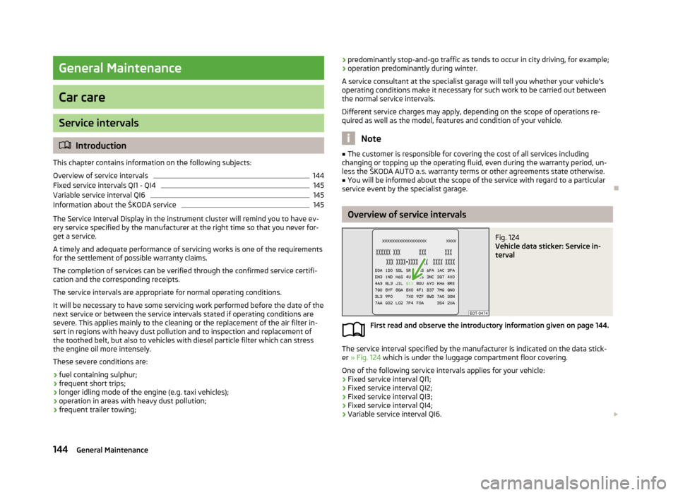
The service interval specified by the manufacturer is indicated on the data stick-
er » Fig. 124 which is under the luggage compartment floor covering.
One of the following service intervals applies for your vehicle: › Fixed service interval QI1;
› Fixed service interval QI2;
› Fixed service interval QI3;
› Fixed service interval QI4;
› Variable service interval QI6.
144General Maintenance
Page 168 of 219

The oil level must be checked at regular intervals. We recommend it be checked
after each time you refuel or prior to making a long journey.
We recommend maintaining the oil level within the range A
, but not above , if
the engine has been operating at high loads, for example, during a lengthy motor-
way trip during the summer months, towing a trailer or negotiating a high moun- tain pass.
The warning light in the instrument cluster will indicate whether the oil level is too low » page 21 , Engine oil . Check the oil level using the dipstick as soon
as possible. Add oil accordingly.
CAUTION
The oil level must on no account be above range A » Fig. 130 . Risk of damaging
the exhaust system!
Note
Engine oil specifications » page 163.
Replenishing
First read and observe the introductory information and safety warn-
ings
on page 163.
›
Check the oil level » page 164.
›
Unscrew the cap of the engine oil filler opening.
›
Replenish the oil in portions of 0.5 litres in accordance with the correct specifi-
cations » page 163 , Specifications and capacity .
›
Check the oil level » page 164.
›
Carefully screw on the oil filler opening cap and push the dipstick in fully.
Changing
First read and observe the introductory information and safety warn-ings
on page 163.
The engine oil must be changed at specified service intervals » page 144 or ac-
cording to the service interval display » page 16, Service Interval Display .
Coolant
Introduction
This chapter contains information on the following subjects:
Capacity
166
Checking the coolant level
166
Replenishing
167
The coolant consists of water with coolant additive. This mixture guarantees anti- freeze protection, protects the cooling/heater system against corrosion and pre-
vents lime formation.
Vehicles exported to countries with a mild climate are already factory-filled with
a coolant which offers antifreeze protection down to about -25 ℃. In these coun-
tries, the concentration of coolant additive should be at least 40%.
Vehicles exported to countries with a cold climate are already factory-filled with a
coolant which offers antifreeze protection down to about -35 °C. In these coun-
tries, the concentration of coolant additive should be at least 50%.
If a higher concentration of antifreeze is required for climatic reasons, the con-centration of coolant additive can be increased up to a maximum of 60% (anti-
freeze protection down to approx. -40 °C).
When refilling, only use the same antifreeze identified on the coolant expansion
vessel » Fig. 131 on page 166.
WARNING■
The engine compartment of your car is a hazardous area. The following
warning instructions must be followed at all times when working in the en-
gine compartment » page 159.■
Do not continue your journey if for some reason it is not possible to top
up the coolant under the prevailing conditions! Switch off the engine and seek
assistance from a specialist garage.
CAUTION
■ The concentration of coolant additive in the coolant must never be under 40%.■Over 60% of coolant additive in the coolant reduces the antifreeze protection
and cooling effect. 165Inspecting and replenishing
Page 178 of 219
545 kg
615 kg
630 kg
650 kg
Speed symbol
This indicates the maximum permissible vehicle speed with fitted tyres in each
category.
170 km/h
180 km/h
190 km/h
200 km/h
210 km/h
240 km/h
270 km/h
CAUTION
The information about the load index and the speed symbol is listed in your vehi-
cle documents.
Unidirectional tyres
First read and observe the introductory information and safety warn-
ings
on page 172.
The direction of rotation of the tyres is marked by arrows on the wall of the tyre.
The indicated direction of rotation must be adhered to in order to ensure the op- timal characteristics of these tyres.
These characteristics mainly relate to the following: › Increased driving stability.
› Reduced risk of aquaplaning.
› Reduced tyre noise and tyre wear.
87919293RSTUHVWTyre pressure monitorFig. 137
Button for setting the tyre infla-
tion pressure control value
First read and observe the introductory information and safety warn-
ings on page 172.
System settings
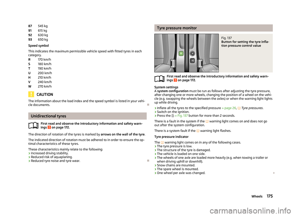
A system configuration must be run as follows after adjusting the tyre pressure,
after changing one or more wheels, changing the position of a wheel on the vehi- cle (e.g. swapping the wheels between the axles) or when the warning light lights
up while driving.
›
Inflate all the tyres to the specified pressure » page 26,
Tyre pressures .
›
Switch on the ignition.
›
Press the
» Fig. 137 button for more than 2 seconds.
There is a fault in the system if the
warning light comes on and does not go
out after the system configuration.
There is a system fault if the
warning light flashes.
Tyre pressure indicator
The
warning light comes on in any of the following cases.
› The tyre pressure is low.
› The structure of the tyre is damaged.
› The vehicle is loaded on one side.
› The wheels of one axle are loaded more heavily (e.g. when towing a trailer or
when driving uphill or downhill).
› Snow chains are mounted.
› The spare wheel is mounted.
› One wheel per axle was changed.
175Wheels
Page 183 of 219
Note■The fire extinguisher must comply with national legal requirements.■Pay attention to the expiration date of the fire extinguisher. Proper functioning
of the fire extinguisher is not assured once it has passed its expiry date.■
The fire extinguisher is part of the scope of delivery in certain countries only.
Vehicle tool kit
Fig. 143
Vehicle tool kit
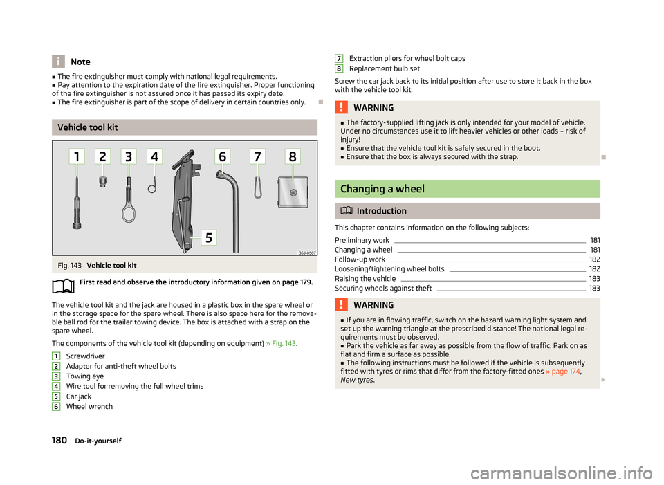
First read and observe the introductory information given on page 179.
The vehicle tool kit and the jack are housed in a plastic box in the spare wheel or
in the storage space for the spare wheel. There is also space here for the remova-
ble ball rod for the trailer towing device. The box is attached with a strap on the spare wheel.
The components of the vehicle tool kit (depending on equipment) » Fig. 143.
Screwdriver
Adapter for anti-theft wheel bolts Towing eye
Wire tool for removing the full wheel trims Car jack
Wheel wrench
123456Extraction pliers for wheel bolt caps
Replacement bulb set
Screw the car jack back to its initial position after use to store it back in the box with the vehicle tool kit.WARNING■ The factory-supplied lifting jack is only intended for your model of vehicle.
Under no circumstances use it to lift heavier vehicles or other loads – risk of
injury!■
Ensure that the vehicle tool kit is safely secured in the boot.
■
Ensure that the box is always secured with the strap.
Changing a wheel
Introduction
This chapter contains information on the following subjects:
Preliminary work
181
Changing a wheel
181
Follow-up work
182
Loosening/tightening wheel bolts
182
Raising the vehicle
183
Securing wheels against theft
183WARNING■ If you are in flowing traffic, switch on the hazard warning light system and
set up the warning triangle at the prescribed distance! The national legal re-
quirements must be observed.■
Park the vehicle as far away as possible from the flow of traffic. Park on as
flat and firm a surface as possible.
■
The following instructions must be followed if the vehicle is subsequently
fitted with tyres or rims that differ from the factory-fitted ones » page 174,
New tyres .
78180Do-it-yourself
Page 184 of 219

WARNINGObserve the following instructions for lifting the vehicle.■If the wheel has to be changed on a slope, first of all block the opposite
wheel with a stone or similar object to prevent the vehicle from unexpectedly
rolling away.■
Secure the base plate of the lifting jack with suitable means to prevent pos-
sible moving. A soft and slippery ground under the base plate may move the lifting jack, causing the vehicle to fall down. It is therefore always necessary to
place the lifting jack on a solid surface or use a wide and stable base. Use a non-slip base (e.g. a rubber foot mat) if the surface is smooth, such as cobbled
stones, tiled floor, etc.
■
Only attach the lifting jack to the attachment points provided for this pur-
pose.
■
Always raise the vehicle with the doors closed.
■
Never position any body parts, such as arms or legs under the vehicle, while
the vehicle is raised with a lifting jack.
■
Never start the engine when the vehicle is raised – risk of injury.
CAUTION
■ The tightening torque specified for the wheel bolts for steel and light alloy
wheels is 120 Nm.■
The anti-theft wheel bolt or the adapter can be damaged if the wheel bolts are
tightened too much.
Note
■ The anti-theft wheel bolt set and adapter can be purchased from a ŠKODA Part-
ner.■
The national legal requirements must be observed when changing a wheel.
Preliminary work
First read and observe the introductory information and safety warn-ings
on page 180.
Always change a wheel on a level surface as far as possible.
The following steps must be carried out before actually changing the wheel:
› Have
all the occupants get out. The passengers should not stand on the road
(instead they should remain behind a crash barrier, for instance) while the wheel is being changed.›
Switch off the engine.
›
Move the gearshift lever into Neutral or move the selector lever for the auto-
matic gearbox into position P.
›
Apply the handbrake firmly.
›
Uncouple a trailer.
›
Remove the vehicle tool kit » page 180 and the spare wheel » page 176 , Spare
wheel from the boot.
Changing a wheel
First read and observe the introductory information and safety warn-
ings
on page 180.
›
Remove the full wheel trim » page 177 or caps » page 177 .
›
In the case of light alloy wheel rims remove the wheel trim cap » page 177.
›
First of all slacken the anti-theft wheel bolt and then the other wheel
bolts » page 182 .
›
Jack up the vehicle until the wheel that needs changing is clear of the
ground » page 183 .
›
Unscrew the wheel bolts and place them on a clean surface (cloth, paper, etc.).
›
Remove the wheel carefully.
›
Attach the spare wheel and slightly screw on the wheel bolts.
›
Lower the vehicle.
›
Tighten the opposite wheel bolts alternately (cross-wise) with the wheel
wrench. Tighten the anti-theft wheel bolt last » page 182.
›
Reinstall the wheel trim/wheel trim cap or the caps.
Note
■
All bolts must be clean and must turn easily.■Under no circumstances grease or oil the wheel bolts!■
When fitting unidirectional tyres, ensure that the direction of rotation is cor-
rect » page 172 .
181Emergency equipment and self-help