2013 SKODA ROOMSTER tailgate
[x] Cancel search: tailgatePage 35 of 219

CAUTIONIf the safe securing system is activated» page 32, the door opening lever and
the central locking buttons do not operate.
Note
■ In the event of an accident in which the airbags are deployed, the locked doors
are automatically unlocked in order to enable rescuers to gain access to the vehi- cle.■
Only the driver's door can be locked or unlocked with the key if the central lock-
ing system fails. The other doors and the tailgate can be locked or unlocked man-
ually. ■ Emergency locking of the door » page 31.
■ Emergency unlocking of the boot lid » page 38.
Individual settings
First read and observe the introductory information and safety warn-
ings
on page 31.
Opening a single door
This selection function makes it possible to only unlock the driver's door. The oth-
er doors remain locked and are only unlocked when the command is repeated.
Automatic locking and unlocking
All the doors and the boot lid are locked automatically once the car reaches a
speed of about 15 km/h.
If the ignition key is withdrawn, the car is then automatically unlocked again. In addition, it is possible for the driver or front passenger to unlock the car by press-
ing the central locking button
» page 33 .
The doors can be unlocked and opened from the inside by pulling on the opening lever of the respective door. By the first pull on the opening lever, the door is un-
locked . By the second pull on the opening lever, the door is opened.
Note
Individual settings can be applied in a specialist workshop.
Safe securing
First read and observe the introductory information and safety warn-
ings
on page 31.
The central locking system is equipped with a safe securing system. The door
locks are blocked automatically if the vehicle is locked from the outside. The warning light flashes for around 2 seconds in quick succession, afterwards it be-gins to flash evenly at longer intervals. It is not possible to open the doors withthe door handle either from the inside or from the outside. This acts as an effec-
tive deterrent for attempts to break into your vehicle.
The safe securing system can be deactivated within 2 seconds by double locking
the vehicle.
If the safe securing system is not operating, the warning light in the driver door flashes for about 2 seconds fast, goes out and starts to flash evenly at longer in-
tervals after about 30 seconds.
The safe securing system is activated again the next time the vehicle is unlocked and locked.
If the vehicle is locked and the safe securing system is deactivated, the door can
be unlocked and opened from the inside by pulling on the opening lever of the respective door. By the first pull on the opening lever, the door is unlocked. By
the second pull on the opening lever, the door is opened.
WARNINGIf the vehicle is locked from the outside and the safe securing system is acti-
vated, there must not be any person in the vehicle as it is then no longer pos-
sible to open either a door or a window from the inside. The locked doors
make it more difficult for rescuers to get into the vehicle in an emergency –
risk to life!
Note
■ The anti-theft alarm system is activated when the vehicle is locked even if the
safe securing system is deactivated. The interior monitor is however not activa- ted.■
You will be informed that the safe securing system is activated after the vehicle
is locked by the CHECK DEADLOCK message on the instrument cluster display. On
vehicles equipped with the MAXI DOT display, the display shows Check deadlock.
Read manual.
32Operation
Page 38 of 219
Folding in the key bit›Press the button 4 » Fig. 16 and fold in the key bit.
Unlocking
The turn signal lights flash twice as confirmation that the vehicle has been un-
locked. If the vehicle is unlocked using button 1
» Fig. 16 and none of the doors
or the tailgate are opened within the next 30 seconds, the vehicle is automatical-
ly locked again and the safe securing system or anti-theft alarm system is reacti- vated. This function is intended to prevent the car being unlocked unintentional-ly.
In addition, when the car is unlocked, the electrically adjustable seats and exteri-
or mirrors move into the position assigned to this key. The stored setting of driver
seat and exterior mirrors is retrieved.
Locking
The turn signal lights flash once to confirm that the vehicle has been correctly
locked.
If the doors or the boot lid remain open after the vehicle has been locked, the
turn signal lights do not flash until they have been closed.
WARNINGIf the car is locked from the outside and the safe securing system is activated,
there must not be any person in the car as it is then not possible to open ei-
ther a door or a window from the inside. The locked doors make it more diffi-
cult for rescuers to get into the vehicle in an emergency – risk to life!
Note
■ Only operate the remote control when the doors and boot lid are closed and the
vehicle is in your line of sight.■
A ŠKODA partner can also activate/deactivate the acoustic signals on vehicles
with an anti-theft alarm system.
Synchronization
First read and observe the introductory information given on page 34.
If the vehicle does not unlock when the remote control is pressed, the key may
not be synchronised. This can occur when the buttons on the remote control key are pressed several times outside the operating range of the equipment or if the
battery in the remote control key has been replaced.
Synchronise the key as follows.
›
Press any button on the remote control key.
›
Unlock the door with the key within 1 minute of pressing the button.
Anti-theft alarm system
Introduction
This chapter contains information on the following subjects:
Operation
36
Interior monitor and towing protection
36
The anti-theft alarm system increases the level of protection against people
seeking to break into the vehicle. The system triggers audible and visual warning
signals if an attempt is made to break into the vehicle.
Note
■ The working life of the alarm siren is 5 years.■Before leaving the vehicle, check that all the doors and windows are closed in
order to ensure that the anti-theft alarm system is fully operational.■
Coding of the radio remote control and the receiver unit precludes the use of
the radio remote control from other vehicles.
35Unlocking and locking
Page 40 of 219

Luggage compartment lid
Introduction
This chapter contains information on the following subjects:
Opening/closing
37
Automatic locking
37
Emergency unlocking
38WARNING■ Ensure that the lock is properly engaged after closing the boot lid. Other-
wise, the tailgate might open suddenly while the vehicle is moving if it was locked – risk of an accident.■
Never drive with the luggage compartment lid open or ajar, as otherwise ex-
haust gases may get into the interior of the vehicle – risk of poisoning!
■
Do not press on the rear window when closing the tailgate, as otherwise
this could crack – there is a risk of injury.
Note
■ After closing the boot lid, it is automatically locked within 1 second and the
anti-theft alarm system is activated. This applies only if the vehicle was locked
before closing the boot lid.■
The function of the handle above the licence plate is deactivated when starting
off or at a speed of 5 km/hour or more for vehicles with central locking. The func-
tion of the handle is activated again when the vehicle has stopped and a door is opened.
Opening/closingFig. 18
Unlock the boot lid/boot lid handle
First read and observe the introductory information and safety warn- ings
on page 37.
After unlocking the vehicle, you can open the lid by pushing the handle located
above the licence plate.
Opening the boot lid for vehicles without central locking
›
Press the
button in the driver's door » Fig. 18 -
and open the tailgate in
the direction of the arrow » Fig. 18 -
.
Opening the boot lid for vehicles with central locking
›
Press the handle and open the tailgate in the direction of the arrow » Fig. 18 -
.
Closing
›
Pull down the tailgate and close it with a gentle swing.
A handle which makes the closing easier is located on the inner panelling of the
boot lid.
Automatic locking
First read and observe the introductory information and safety warn-
ings
on page 37.
If the vehicle was locked before the tailgate was closed, the lid is locked automat-
ically immediately it is closed.
37Unlocking and locking
Page 41 of 219
The period after which the tailgate locks automatically can be extended by a spe-
cialist garage.
Delayed locking
If the tailgate was opened with the button on the remote control key, then it
is possible to open the lid within a limited period of it being closed.
There is a risk of unwanted entry into the vehicle before the boot lid is locked au-tomatically. Therefore always lock the vehicle with the button on the remote
control.
Delayed locking can be disabled by a specialist garage at any time.
Note
More detailed information is available from a ŠKODA Partner.
Emergency unlocking
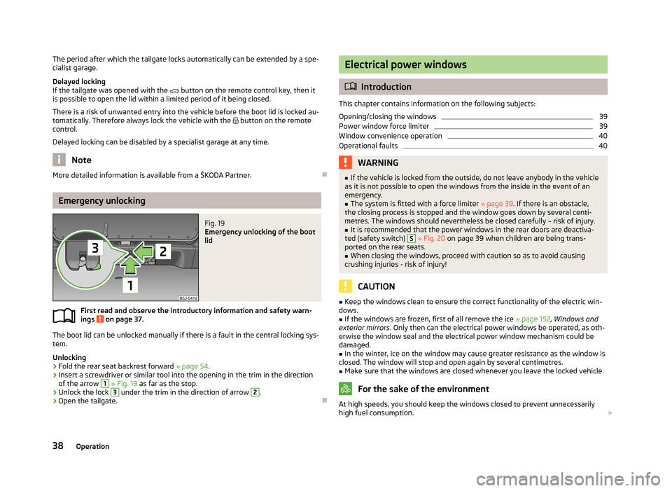
Fig. 19
Emergency unlocking of the boot
lid
First read and observe the introductory information and safety warn-
ings on page 37.
The boot lid can be unlocked manually if there is a fault in the central locking sys-
tem.
Unlocking
›
Fold the rear seat backrest forward » page 54.
›
Insert a screwdriver or similar tool into the opening in the trim in the direction
of the arrow
1
» Fig. 19 as far as the stop.
›
Unlock the lock
3
under the trim in the direction of arrow
2
.
›
Open the tailgate.
Electrical power windows
Introduction
This chapter contains information on the following subjects:
Opening/closing the windows
39
Power window force limiter
39
Window convenience operation
40
Operational faults
40WARNING■ If the vehicle is locked from the outside, do not leave anybody in the vehicle
as it is not possible to open the windows from the inside in the event of an
emergency.■
The system is fitted with a force limiter » page 39. If there is an obstacle,
the closing process is stopped and the window goes down by several centi-
metres. The windows should nevertheless be closed carefully – risk of injury.
■
It is recommended that the power windows in the rear doors are deactiva-
ted (safety switch)
S
» Fig. 20 on page 39 when children are being trans-
ported on the rear seats.
■
When closing the windows, proceed with caution so as to avoid causing
crushing injuries - risk of injury!
CAUTION
■ Keep the windows clean to ensure the correct functionality of the electric win-
dows.■
If the windows are frozen, first of all remove the ice » page 152, Windows and
exterior mirrors . Only then can the electrical power windows be operated, as oth-
erwise the window seal and the electrical power window mechanism could be
damaged.
■
In the winter, ice on the window may cause greater resistance as the window is
closed. The window will stop and open again by several centimetres.
■
Make sure that the windows are closed whenever you leave the locked vehicle.
For the sake of the environment
At high speeds, you should keep the windows closed to prevent unnecessarily
high fuel consumption. 38Operation
Page 50 of 219
Illuminated storage compartment on the passenger sideFirst read and observe the introductory information given on page 46.›
When opening the flap of the storage compartment on the front passenger side
the lighting in the storage compartment comes on.
›
The light switches on automatically when the parking light is switched on and
goes out when the flap is closed.
Luggage compartment light
First read and observe the introductory information given on page 46.
The light comes on automatically when the boot lid is opened. If the tailgate re-
mains open for more than 10 minutes, the luggage compartment light switches
off automatically.
Visibility
Introduction
This chapter contains information on the following subjects:
Rear window heater
47
Sun visors
48
sunshade
48
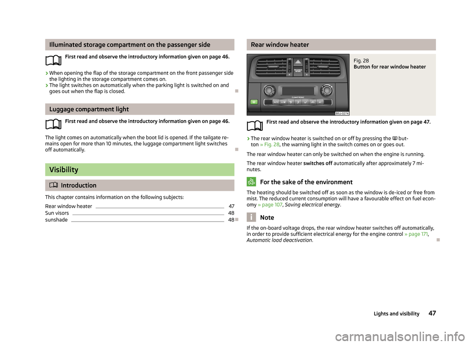
Rear window heaterFig. 28
Button for rear window heater
First read and observe the introductory information given on page 47.
›
The rear window heater is switched on or off by pressing the
but-
ton » Fig. 28 , the warning light in the switch comes on or goes out.
The rear window heater can only be switched on when the engine is running. The rear window heater switches off automatically after approximately 7 mi-
nutes.
For the sake of the environment
The heating should be switched off as soon as the window is de-iced or free from
mist. The reduced current consumption will have a favourable effect on fuel econ-
omy » page 107 , Saving electrical energy .
Note
If the on-board voltage drops, the rear window heater switches off automatically,
in order to provide sufficient electrical energy for the engine control » page 171,
Automatic load deactivation .
47Lights and visibility
Page 77 of 219
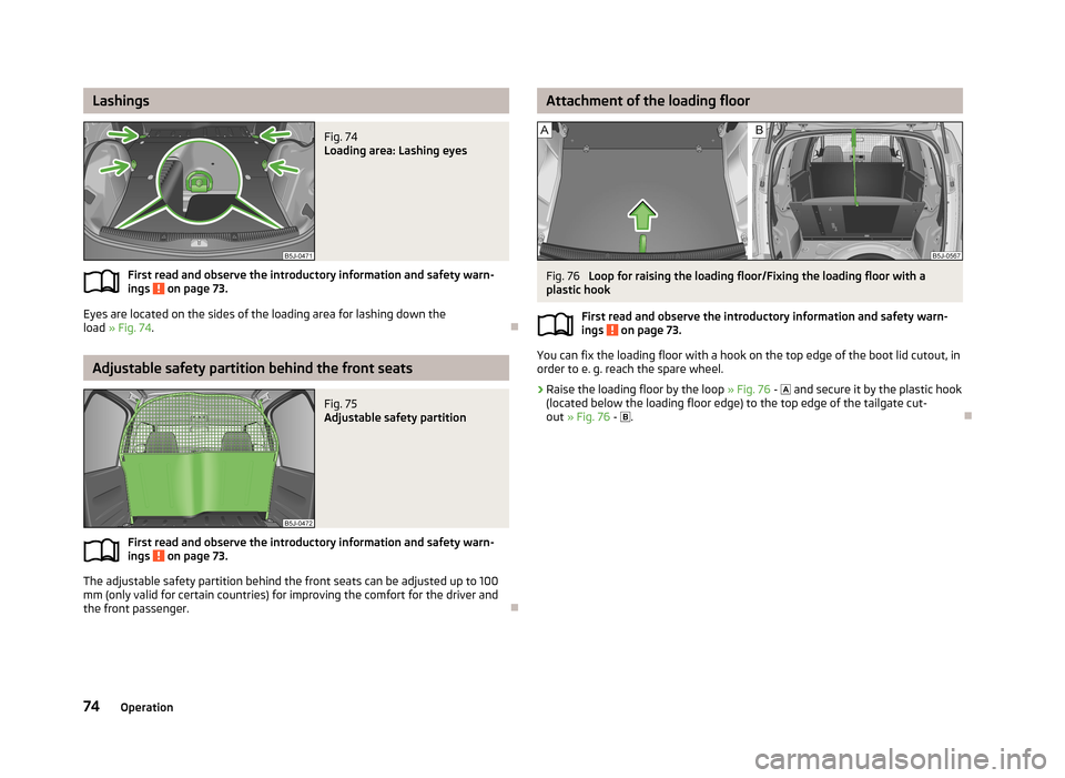
LashingsFig. 74
Loading area: Lashing eyes
First read and observe the introductory information and safety warn-ings on page 73.
Eyes are located on the sides of the loading area for lashing down the
load » Fig. 74 .
Adjustable safety partition behind the front seats
Fig. 75
Adjustable safety partition
First read and observe the introductory information and safety warn-
ings on page 73.
The adjustable safety partition behind the front seats can be adjusted up to 100
mm (only valid for certain countries) for improving the comfort for the driver and
the front passenger.
Attachment of the loading floorFig. 76
Loop for raising the loading floor/Fixing the loading floor with a
plastic hook
First read and observe the introductory information and safety warn-ings
on page 73.
You can fix the loading floor with a hook on the top edge of the boot lid cutout, inorder to e. g. reach the spare wheel.
›
Raise the loading floor by the loop » Fig. 76 -
and secure it by the plastic hook
(located below the loading floor edge) to the top edge of the tailgate cut-
out » Fig. 76 -
.
74Operation
Page 179 of 219

WARNING■When the warning light illuminates, immediately reduce the speed and
avoid sudden steering and brake manoeuvres. Stop the vehicle as soon as
possible and inspect the tyres and their inflation pressure.■
Under certain circumstances (e.g. a racy style of driving, wintry or unpaved
roads), the warning light may be delayed or does not light up at all.
CAUTION
■
The tyre control display does therefore not replace the regular tyre inflation
pressure control, as the system cannot detect an even loss of pressure.■
The system cannot warn in case of very rapid loss of tyre pressure, e.g. in the
event of a sudden puncture. In this case carefully bring the vehicle to a standstill without sudden steering movements or sharp braking.
■
The basic setting must be repeated every 10,000 km or once a year to ensure
proper functioning of the tyre pressure monitor.
Spare wheel
Fig. 138
Boot: Spare wheel
First read and observe the introductory information and safety warn-
ings on page 172.
The spare wheel is located in a well under the floor covering in the luggage com-
partment and held by a special nut » Fig. 138.
Taking the wheel out
›
Open the tailgate.
›
Lift up the floor in the luggage compartment.
›
Remove the box with the tool kit.
›
Unscrew the nut » Fig. 138 anticlockwise.
›Take out the wheel.
Stowing the wheel›
Stow the replaced wheel in the spare wheel well with the rim facing down.
›
Screw on the nut » Fig. 138 clockwise until the wheel is safely secured.
›
Replace the box with the tool kit into the spare wheel and secure it with the
tape.
›
Fold back the floor in the luggage compartment.
›
Close the boot lid.
Fit a wheel in the appropriate dimensions and design as soon as possible.
If the dimensions or design of the spare wheel differ from the tyres fitted to the
vehicle (e.g. winter tyres or low-profile tyres), it must only be used briefly in the
event of a puncture and if an appropriately cautious style of driving is adop-
ted »
.
Temporary spare wheel
A warning label is displayed on the rim of the temporary spare wheel.
Please note the following if you intend to use the temporary spare wheel. › The warning label must not be covered after installing the wheel.
› Be particularly observant when driving.
› The inflation pressure for the temporary spare wheel is identical to the maxi-
mum inflation pressure for the standard tyres.
› Only use this temporary spare wheel to reach the nearest specialist garage, as it
is not intended for long-term use.
WARNING■ Never use the temporary spare wheel if it is damaged.■If the dimensions or design of the temporary spare wheel differ from the fit-
ted tyres, never drive faster than 80 km/h (or 50 mph).■
Avoid accelerating at full throttle, sharp braking and fast cornering.
CAUTION
Observe the instructions on the warning sticker on the temporary spare wheel.
176General Maintenance
Page 200 of 219
›Turn the connector with the bulb in
counter-clockwise up to the stop and re-
move.›
Replace the bulb, insert the holder with the new bulb and turn clockwise to the
stop.
›
To re-install the fog light, first of all place the fog light with the lug on the side opposite the licence plate.
›
Press in the fog lamp on the side closest to the licence plate.
›
Insert the cap, beginning with the lug on the side opposite the license plate.
›
Press in the cap on the side facing the license plate. The cap must engage firm-
ly.
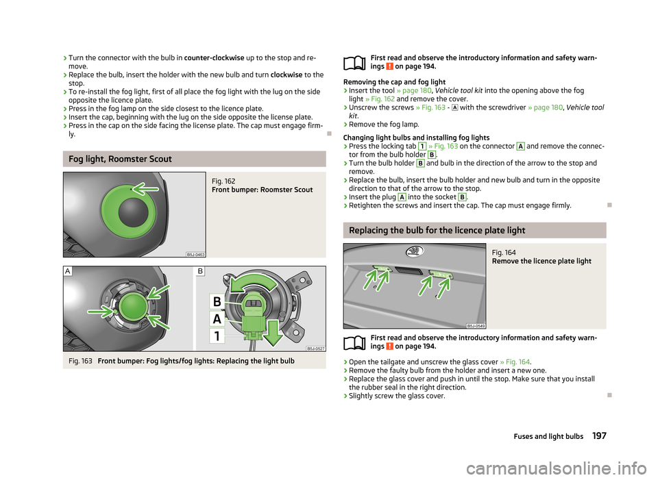
Fog light, Roomster Scout
Fig. 162
Front bumper: Roomster Scout
Fig. 163
Front bumper: Fog lights/fog lights: Replacing the light bulb
First read and observe the introductory information and safety warn-
ings on page 194.
Removing the cap and fog light
›
Insert the tool » page 180, Vehicle tool kit into the opening above the fog
light » Fig. 162 and remove the cover.
›
Unscrew the screws » Fig. 163 - with the screwdriver » page 180, Vehicle tool
kit .
›
Remove the fog lamp.
Changing light bulbs and installing fog lights
›
Press the locking tab
1
» Fig. 163 on the connector
A
and remove the connec-
tor from the bulb holder
B
.
›
Turn the bulb holder
B
and bulb in the direction of the arrow to the stop and
remove.
›
Replace the bulb, insert the bulb holder and new bulb and turn in the opposite direction to that of the arrow to the stop.
›
Insert the plug
A
into the socket
B
.
›
Retighten the screws and insert the cap. The cap must engage firmly.
Replacing the bulb for the licence plate light
Fig. 164
Remove the licence plate light
First read and observe the introductory information and safety warn-ings on page 194.
›
Open the tailgate and unscrew the glass cover » Fig. 164.
›
Remove the faulty bulb from the holder and insert a new one.
›
Replace the glass cover and push in until the stop. Make sure that you install
the rubber seal in the right direction.
›
Slightly screw the glass cover.
197Fuses and light bulbs