2013 SKODA ROOMSTER ESP
[x] Cancel search: ESPPage 42 of 219
Note■After switching the ignition off, it is still possible to open or close the windows
for approx. 10 minutes. The electrical power windows are only switched off com- pletely once the driver's door or front passenger door are opened.■
When driving always use the existing heating, air conditioning and ventilation
system for ventilating the interior of the vehicle. If the windows are opened, dust
as well as other dirt can get into the vehicle and in addition the wind noise is
more at certain speeds.
Opening/closing the windows
Fig. 20
Buttons on the driver's door/in the rear doors
First read and observe the introductory information and safety warn-
ings
on page 38.
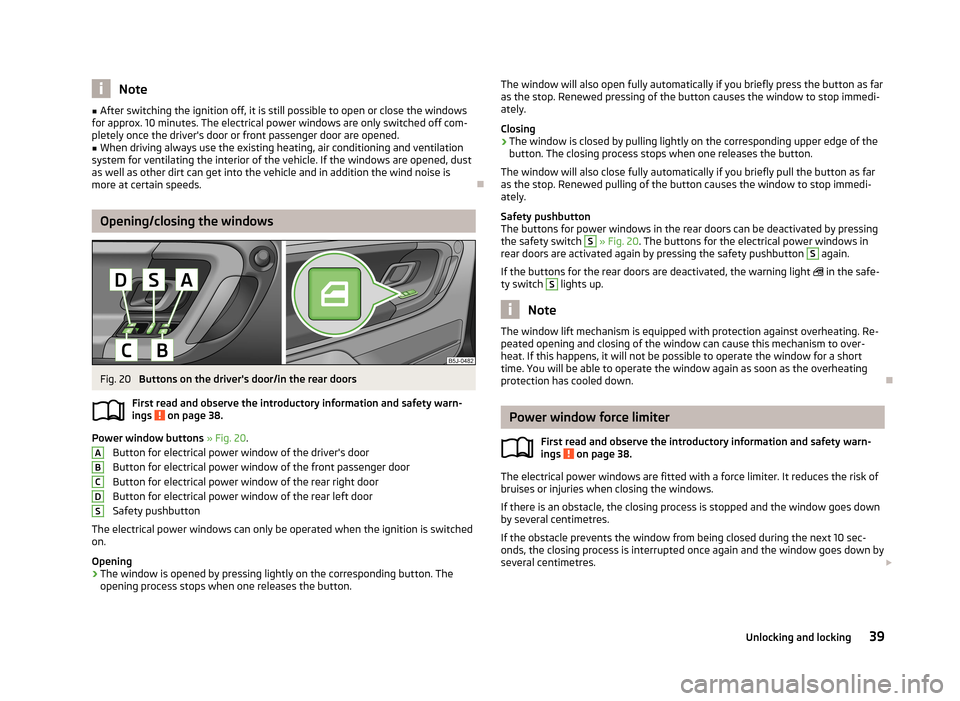
Power window buttons » Fig. 20 .
Button for electrical power window of the driver's door
Button for electrical power window of the front passenger door
Button for electrical power window of the rear right door Button for electrical power window of the rear left door
Safety pushbutton
The electrical power windows can only be operated when the ignition is switched
on.
Opening
›
The window is opened by pressing lightly on the corresponding button. The opening process stops when one releases the button.
ABCDSThe window will also open fully automatically if you briefly press the button as far
as the stop. Renewed pressing of the button causes the window to stop immedi- ately.
Closing›
The window is closed by pulling lightly on the corresponding upper edge of the
button. The closing process stops when one releases the button.
The window will also close fully automatically if you briefly pull the button as far as the stop. Renewed pulling of the button causes the window to stop immedi-
ately.
Safety pushbutton
The buttons for power windows in the rear doors can be deactivated by pressing
the safety switch
S
» Fig. 20 . The buttons for the electrical power windows in
rear doors are activated again by pressing the safety pushbutton
S
again.
If the buttons for the rear doors are deactivated, the warning light
in the safe-
ty switch
S
lights up.
Note
The window lift mechanism is equipped with protection against overheating. Re-
peated opening and closing of the window can cause this mechanism to over-
heat. If this happens, it will not be possible to operate the window for a short
time. You will be able to operate the window again as soon as the overheating
protection has cooled down.
Power window force limiter
First read and observe the introductory information and safety warn-
ings
on page 38.
The electrical power windows are fitted with a force limiter. It reduces the risk of
bruises or injuries when closing the windows.
If there is an obstacle, the closing process is stopped and the window goes down
by several centimetres.
If the obstacle prevents the window from being closed during the next 10 sec-
onds, the closing process is interrupted once again and the window goes down by several centimetres.
39Unlocking and locking
Page 44 of 219
Lights and visibility
Lights
Introduction
This chapter contains information on the following subjects:
Parking and low beam lights
41
Headlight beam adjustment
42
Daylight running lights (DAY LIGHT)
42
Turn signal and main beam lights
43
Halogen projector headlights with cornering light function
43
Fog lights
44
Foglights with the CORNER function
44
Rear fog light
44
Tourist lights
44
Hazard warning light system
45
Parking lights
45
Unless otherwise stated, the lights only work when the ignition is on.
The layout of the controls differs in part from that shown in » Fig. 21 on page 41
on right-hand drive vehicles. The symbols which mark the positions of the con-
trols are identical.
WARNING■ Never drive with only the side lights on! The side lights are not bright
enough to light up the road sufficiently in front of you or to be seen by other
oncoming traffic. Therefore always switch on the low beam when it is dark or
if visibility is poor.■
The activation of the lights should only be undertaken in accordance with
national legal requirements.
■
The driver is always responsible for the correct settings and use of the
lights.
NoteThe headlights may mist up temporarily. When the driving lights are switched on,
the light outlet areas are free from condensation after a short time, although the
headlight lenses may still be misted up around the edge. This mist has no influ-
ence on the life of the lighting system.
Parking and low beam lights
Fig. 21
Dash panel: Light switch
First read and observe the introductory information and safety warn-
ings on page 41.
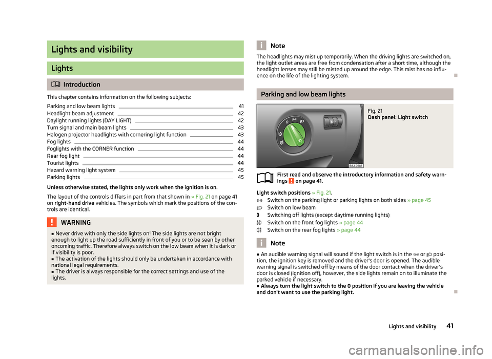
Light switch positions » Fig. 21 .
Switch on the parking light or parking lights on both sides » page 45
Switch on low beam
Switching off lights (except daytime running lights) Switch on the front fog lights » page 44
Switch on the rear fog lights » page 44
Note
■
An audible warning signal will sound if the light switch is in the or posi-
tion, the ignition key is removed and the driver's door is opened. The audible warning signal is switched off by means of the door contact when the driver's door is closed (ignition off), however, the side lights remain on to illuminate the
parked vehicle if necessary.■
Always turn the light switch to the 0 position if you are leaving the vehicle
and don't want to use the parking light.
41Lights and visibility
Page 45 of 219

Headlight beam adjustmentFig. 22
Dash panel: Lights and visibility
First read and observe the introductory information and safety warn-
ings on page 41.
Turning the rotary switch » Fig. 22 from position
to
gradually adjusts the
headlight beam thereby shortening the beam of light.
The positions of the rotary switch correspond approximately to the following
car load.
Front seats occupied, boot empty.
All seats occupied, boot empty.
All seats occupied, boot loaded.
Driver seat occupied, boot loaded.
WARNINGAlways adjust the headlight beam to satisfy the following conditions.■The vehicle does not dazzle other road users, especially oncoming vehicles.■
The beam range is sufficient for safe driving.
Note
We recommend you adjust the headlight beam when the low beam is switched
on.
Daylight running lights (DAY LIGHT)
First read and observe the introductory information and safety warn-
ings
on page 41.
Switching on daytime running lights
›
Turn the light switch to position 0 » Fig. 21 on page 41.
Activating/deactivating the daytime running lights function
›
Activate and deactivate the daytime running lights by fitting/removing the fuse
with the appropriate ampere rating for daytime running lights » page 192,
Fuses in the dash panel .
Deactivating on vehicles with the START-STOP system
›
Switch off the ignition.
›
At the same time, pull the turn signal light stalk » Fig. 23 on page 43 towards
the steering wheel, push it downwards, and hold it in this position.
›
Switch on the ignition - wait until the left-turn signal light flashes 4x.
›
Switch off the ignition - an audible signal sounds which confirms the deactiva- tion of the daylight driving lights.
›
Release the turn signal stalk.
Activating on vehicles with the START-STOP system
›
Switch off the ignition.
›
At the same time, pull the turn signal light stalk » Fig. 23 on page 43 towards
the steering wheel, push it upwards, and hold it in this position.
›
Switch on the ignition - wait until the right-turn signal light flashes 4x.
›
Switch off the ignition - an audible signal sounds which confirms the activation
of the daylight driving lights.
›
Release the turn signal stalk.
On vehicles with separate lights for daylight driving lights in the fog lights or in
the front bumper, the parking lights and the licence plate light do not come on
when activating the function daylight driving lights (neither front nor rear).
If the vehicle is not equipped with separate lights for daylight driving lights, the
combination of the low beam, the parking lights (front and rear) including the li-
cence plate light is used as daylight driving lights.
Note
The daytime driving lights also serve as parking lights on vehicles with separate
lights for daylight driving lights (in the bumper below the main headlights).
42Operation
Page 58 of 219
Fold downseat backrest and seat fold down completelyFig. 39
Fold seat fully forwards/lock folded forward seats
First read and observe the introductory information given on page 54.
Folding the seat backrest forwards
›
Put the belt tongue into the opening on the respective side of the vehicle -
safety position.
›
Remove the head restraint from the rear middle seat » page 56, Head re-
straints .
›
Push the outer rear seats towards the rear as far as they will go » page 54, Set-
ting theSetting the seats in the longitudinal direction .
›
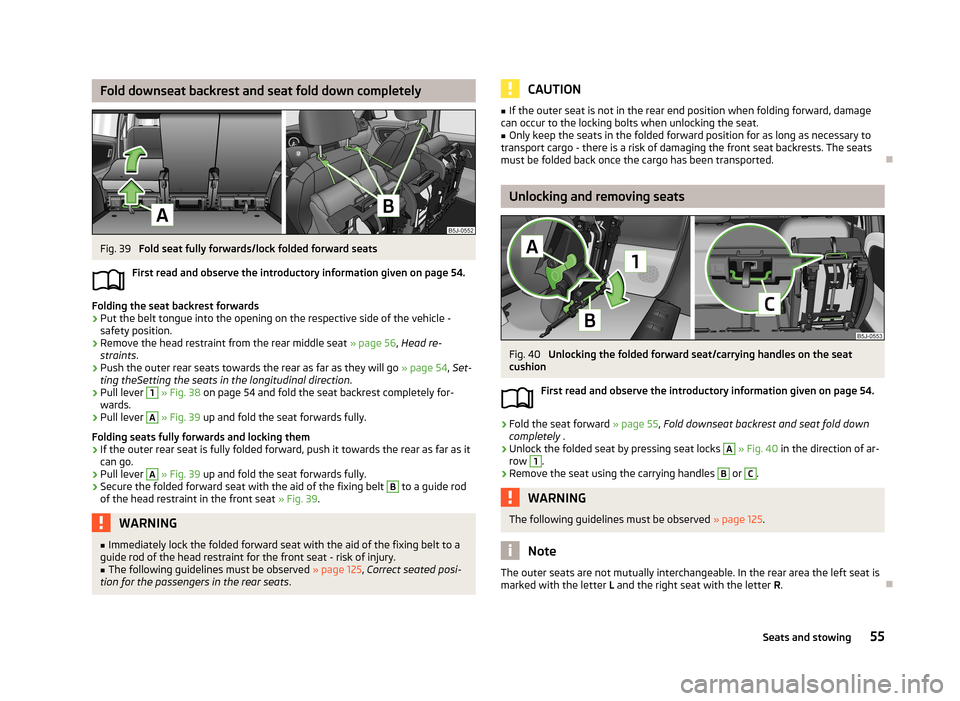
Pull lever
1
» Fig. 38 on page 54 and fold the seat backrest completely for-
wards.
›
Pull lever
A
» Fig. 39 up and fold the seat forwards fully.
Folding seats fully forwards and locking them
›
If the outer rear seat is fully folded forward, push it towards the rear as far as it
can go.
›
Pull lever
A
» Fig. 39 up and fold the seat forwards fully.
›
Secure the folded forward seat with the aid of the fixing belt
B
to a guide rod
of the head restraint in the front seat » Fig. 39.
WARNING■
Immediately lock the folded forward seat with the aid of the fixing belt to a
guide rod of the head restraint for the front seat - risk of injury.■
The following guidelines must be observed » page 125, Correct seated posi-
tion for the passengers in the rear seats .CAUTION■
If the outer seat is not in the rear end position when folding forward, damage
can occur to the locking bolts when unlocking the seat.■
Only keep the seats in the folded forward position for as long as necessary to
transport cargo - there is a risk of damaging the front seat backrests. The seats must be folded back once the cargo has been transported.
Unlocking and removing seats
Fig. 40
Unlocking the folded forward seat/carrying handles on the seat
cushion
First read and observe the introductory information given on page 54.
›
Fold the seat forward » page 55, Fold downseat backrest and seat fold down
completely .
›
Unlock the folded seat by pressing seat locks
A
» Fig. 40 in the direction of ar-
row
1
.
›
Remove the seat using the carrying handles
B
or
C
.
WARNINGThe following guidelines must be observed » page 125.
Note
The outer seats are not mutually interchangeable. In the rear area the left seat is
marked with the letter L and the right seat with the letter R.
55Seats and stowing
Page 60 of 219
WARNING■The head restraints must be correctly adjusted in order to offer effective
protection for the occupants in the event of an accident.■
Never drive with the head restraints removed - risk of injury.
■
If the rear seats are occupied, the rear head restraint must not be in the
lower position.
headrest adjust
Fig. 43
Head restraint: adjusting/removing
First read and observe the introductory information and safety warn- ings
on page 56.
Setting height
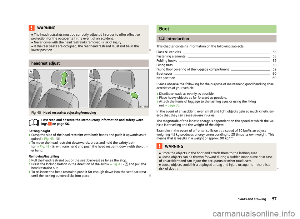
›
Grasp the side of the head restraint with both hands and push it upwards as re-
quired » Fig. 43 -
.
›
To move the head restraint downwards, press and hold the safety but-
ton » Fig. 43 -
with one hand and push the head restraint down with the oth-
er hand.
Removing/installing
›
Pull the head restraint out of the seat backrest as far as the stop.
›
Press the locking button in the direction of the arrow » Fig. 43 -
and pull the
head restraint out.
›
To re-insert the head restraint, push it far enough down into the seat backrest until the locking button clicks into place.
Boot
Introduction
This chapter contains information on the following subjects:
Class N1 vehicles
58
Fastening elements
58
Folding hooks
59
Fixing nets
59
Fixing floor covering of the luggage compartment
59
Boot cover
60
Net partition
60
Please observe the following for the purpose of maintaining good handling char-
acteristics of your vehicle:
›
Distribute loads as evenly as possible.
›
Place heavy objects as far forward as possible.
›
Attach the items of luggage to the lashing eyes or using the fixing net » page 58 .
In the event of an accident, even small and light objects gain so much kinetic en-
ergy that they can cause severe injuries.
The magnitude of the kinetic energy is dependent on the speed at which the ve-
hicle is travelling and the weight of the object.
Example: In the event of a frontal collision at a speed of 50 km/h, an object
weighing 4.5 kg produces energy corresponding to 20 times its own weight. This
means that it results in a weight of approx. 90 kg “ ”.
WARNING■ Store the objects in the boot and attach them to the lashing eyes.■Loose objects can be thrown forward during a sudden manoeuvre or in case
of an accident and can injure the occupants or other road users.■
Loose objects could hit a deployed airbag and injure occupants – there is a
risk of death.
57Seats and stowing
Page 83 of 219

We recommend that you leave the air outlet vents 3 » Fig. 80 on page 77 in the
open position in all operating modes.
Note
If the air distribution is set only to the windows, the entire volume of air is used
to defrost the windows and thus no air will be fed to the footwell. This can limit
the heating comfort.
Recirculated air mode
First read and observe the introductory information given on page 78.
Recirculated air mode prevents polluted air from outside the vehicle getting into
the vehicle, for example when driving through a tunnel or when standing in a
traffic jam.
Switching on/off
›
Press the
button.
The indicator light in the button lights up.
›
Press the
button again.
The indicator light in the button goes out.
Recirculated air mode is switched off automatically if the air distribution control
C
» Fig. 81 on page 79 is turned to the
position. Recirculated air mode can be
switched on again from this setting by pressing the
button again.
WARNINGNever leave recirculated air mode on over a longer period of time, as “stale air”
can cause fatigue of the driver and the passengers, reduce attention levels
and also cause the windows to mist up. The risk of having an accident increa-
ses. Switch off recirculated air mode as soon as the windows start to mist up.
Air conditioning system (manual air conditioning
system)
Introduction
This chapter contains information on the following subjects: Operation
81
Setting the air conditioning system
82
Recirculated air mode
82
The cooling system operates only if the following conditions are met. The cooling system is switched on » page 81.
The engine is running.
The outside temperature is above approximately +2 °C.
The blower switch is switched on (positions 1-4).
If the desired interior temperature can also be achieved without activating the cooling system, fresh air mode should be selected.
If the coolant temperature is too high, the cooling system is switched off to en-
sure that the engine cools down.
CAUTION
■ Under certain circumstances, air at a temperature of about 5 °C can flow out of
the vents when the cooling system is switched on.■
Lengthy and uneven distribution of the air flow out of the vents (especially
around the feet) and large differences in temperature, for example, when getting
out of the vehicle, can cause susceptible individuals to catch a cold.
Note
We recommend that you have the air conditioning system cleaned by a specialist
garage once every year.80Operation
Page 87 of 219

Air flow to the windows
Air flow to the upper body
Air flow in the footwell
Recirculating air operation on/off » page 84
Switch cooling system on/off
Note
Do not stick anything on or cover the interior temperature sensor 11 » Fig. 83 ; it
could have an unfavourable effect on the Climatronic system.
automatic mode
First read and observe the introductory information given on page 83.
The automatic mode is used in order to maintain a constant temperature and to
demist the windows in the interior of the car.
Switching on
›
Set a temperature between +18 °C and +29 ℃.
›
Move the air outlet vents 3 » Fig. 80 on page 77 and 4 so that the air flow is
directed slightly upwards.
›
Press the
button » Fig. 83 on page 83;
will appear in the display.
Automatic mode can be switched off by pressing any of the air distribution but-
tons or by increasing/decreasing the blower speed. The temperature is neverthe-
less regulated.
Setting the temperature
First read and observe the introductory information given on page 83.
Setting temperature
›
Switch on the ignition.
›
Turn the control dial
1
» Fig. 83 on page 83 to the left or to the right to in-
crease or decrease the temperature.
Switching between Celsius and Fahrenheit
›
Press and hold the
and
buttons simultaneously.
The information appears in the display in the desired temperature unit (no.3
» Fig. 83 on page 83).
The interior temperature can be set between +18 °C and +29 ℃. The interior tem-
perature is regulated automatically within this range.
If you set the temperature below +18 ℃, “LO” appears in the display.
If you set a temperature higher than +29 ℃, “HI” appears in the display.
Climatronic operates at maximum cooling or heating capacity respectively at ei- ther end position. There will be no automatic temperature control.
CAUTION
Lengthy and uneven distribution of the air flow out of the vents (especially
around the feet) and large differences in temperature, for example, when getting
out of the vehicle, can cause susceptible individuals to catch a cold.
Recirculated air mode
First read and observe the introductory information given on page 83.
Recirculated air mode prevents polluted air from outside the vehicle getting intothe vehicle, for example when driving through a tunnel or when standing in a
traffic jam.
Switching on
›
Press the
button » Fig. 83 on page 83.
The display shows the
icon.
Switching off
›
Press the
button » Fig. 83 on page 83 again.
The
icon in the display goes out.
WARNINGNever leave recirculated air mode on over a longer period of time, as “stale air”
can cause fatigue of the driver and the passengers, reduce attention levels
and also cause the windows to mist up. The risk of having an accident increa-
ses. Switch off recirculated air mode as soon as the windows start to mist up. 84Operation
Page 88 of 219
NoteIf recirculated air mode is switched on for around 15 minutes, the symbol will
begin to flash in the display as a sign that the recirculated air mode is switched on long-term. If the recirculated air mode is not switched off, the symbol flashes for
around 5 minutes.
Controlling blower
First read and observe the introductory information given on page 83.
The Climatronic system controls the blower stages automatically in line with the
interior temperature. However, the blower level can be manually adjusted to suit your particular needs.
›
Turn control dial
10
» Fig. 83 on page 83 to the left or to the right to increase or
decrease the blower speed.
If the blower is switched off, the Climatronic system is switched off.
The blower speed set is indicated by displaying the corresponding number of seg-
ments in icon
9
» Fig. 83 on page 83 in the display.
WARNING■
“Stale air” may result in fatigue in the driver and occupants, reduce attention
levels and also cause the windows to mist up. The risk of having an accident
increases.■
Do not switch off the Climatronic system for longer than necessary.
■
Switch on the Climatronic system as soon as the windows mist up.
Defrosting windscreen
First read and observe the introductory information given on page 83.
Switching on
›
Press the
button » Fig. 83 on page 83.
Switching off
›
Press the
button » Fig. 83 on page 83 again or press the
button.
More air flows out of the air outlet vents 1 and 2 » Fig. 80 on page 77. The tem-
perature control is controlled automatically.
85Heating and air-conditioning