2013 SKODA ROOMSTER run flat
[x] Cancel search: run flatPage 176 of 219

WARNINGObserve the following information regarding the wheel bolts.■The wheel bolts must be clean and must turn easily. Never apply grease or
oil.■
The prescribed tightening torque of the wheel bolts for steel and light alloy
wheels is 120 Nm.
■
If the wheel bolts are tightened to an insufficient tightening torque, the
rims may come loose when the car is moving – risk of accident! A tightening
torque which is too high can damage the bolts and threads and this can result
in permanent deformation of the contact surfaces on the rim.
■
If the wheel bolts are handled incorrectly, the wheel may come loose when
the car is moving – risk of accident!
WARNINGObserve the following information regarding the spare wheel.■Only use the spare wheel for as long as is necessary.■
Never drive with more than one spare wheel attached.
■
The snow chains cannot be used on the spare wheel.
CAUTION
■ If a spare wheel is used that is not identical to the fitted tyres, the following
must be observed » page 176, Spare wheel .■
Protect the tyres from contact with oil, grease and fuel.
■
Replace lost valve caps.
■
If, in the event of a puncture, it is necessary to fit a spare wheel with a tyre
without a dedicated running direction or with the opposite direction of rotation, drive carefully as the optimal characteristics of the tyre are no longer applicable in
this situation.
For the sake of the environment
Tyres that are insufficiently inflated increase your fuel consumption.
Note
■ We recommend that any work on the wheels or tyres be carried out by a spe-
cialist garage.■
We recommend that you use wheel rims, tyres, full wheel trims and snow chains
from ŠKODA Original Accessories.
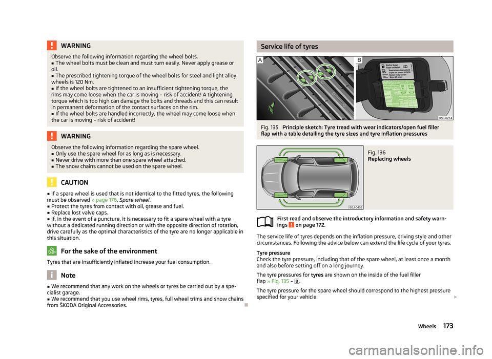
Service life of tyresFig. 135
Principle sketch: Tyre tread with wear indicators/open fuel filler
flap with a table detailing the tyre sizes and tyre inflation pressures
Fig. 136
Replacing wheels
First read and observe the introductory information and safety warn-
ings on page 172.
The service life of tyres depends on the inflation pressure, driving style and other
circumstances. Following the advice below can extend the life cycle of your tyres.
Tyre pressure
Check the tyre pressure, including that of the spare wheel, at least once a month and also before setting off on a long journey.
The tyre pressures for tyres are shown on the inside of the fuel filler
flap » Fig. 135 –
.
The tyre pressure for the spare wheel should correspond to the highest pressure
specified for your vehicle.
173Wheels
Page 178 of 219

545 kg
615 kg
630 kg
650 kg
Speed symbol
This indicates the maximum permissible vehicle speed with fitted tyres in each
category.
170 km/h
180 km/h
190 km/h
200 km/h
210 km/h
240 km/h
270 km/h
CAUTION
The information about the load index and the speed symbol is listed in your vehi-
cle documents.
Unidirectional tyres
First read and observe the introductory information and safety warn-
ings
on page 172.
The direction of rotation of the tyres is marked by arrows on the wall of the tyre.
The indicated direction of rotation must be adhered to in order to ensure the op- timal characteristics of these tyres.
These characteristics mainly relate to the following: › Increased driving stability.
› Reduced risk of aquaplaning.
› Reduced tyre noise and tyre wear.
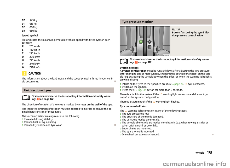
87919293RSTUHVWTyre pressure monitorFig. 137
Button for setting the tyre infla-
tion pressure control value
First read and observe the introductory information and safety warn-
ings on page 172.
System settings
A system configuration must be run as follows after adjusting the tyre pressure,
after changing one or more wheels, changing the position of a wheel on the vehi- cle (e.g. swapping the wheels between the axles) or when the warning light lights
up while driving.
›
Inflate all the tyres to the specified pressure » page 26,
Tyre pressures .
›
Switch on the ignition.
›
Press the
» Fig. 137 button for more than 2 seconds.
There is a fault in the system if the
warning light comes on and does not go
out after the system configuration.
There is a system fault if the
warning light flashes.
Tyre pressure indicator
The
warning light comes on in any of the following cases.
› The tyre pressure is low.
› The structure of the tyre is damaged.
› The vehicle is loaded on one side.
› The wheels of one axle are loaded more heavily (e.g. when towing a trailer or
when driving uphill or downhill).
› Snow chains are mounted.
› The spare wheel is mounted.
› One wheel per axle was changed.
175Wheels
Page 189 of 219

›Remove the empty tyre inflator bottle from the valve.›Screw the valve core back into the tyre valve using the valve remover 1.
Inflating›
Screw the air compressor tyre inflation hose
5
» Fig. 148 on page 185 firmly on-
to the tyre valve.
›
Check that the air release valve
7
is closed.
›
Start the engine and run it in idle.
›
Plug the connector
9
into 12 Volt socket » page 67, 12-volt power outlet .
›
Switch on the air compressor with the ON and OFF switch
8
.
›
Allow the air compressor to run until a pressure of 2.0 - 2.5 bar is achieved. Max-
imum run time of 8 minutes » !
›
Switch off the air compressor.
›
If you cannot reach an air pressure of 2.0 – 2.5 bar, unscrew the tyre inflation
hose
5
from the tyre valve.
›
Drive the vehicle 10 metres forwards or backwards to allow the sealing agent to
“distribute” in the tyre.
›
Firmly screw the tyre inflation hose
5
back onto the tyre valve and repeat the
inflation process.
›
If you cannot reach the required tyre inflation pressure here either, this means
the tyre has sustained too much damage. You cannot seal with tyre with the breakdown kit »
.
›
Switch off the air compressor.
›
Remove the tyre inflation hose
5
from the tyre valve.
Once a tyre pressure of 2.0 – 2.5 bar is reached, the journey may be continued at a maximum speed of 80 km/h (50 mph).
Check the tyre inflation pressure after driving for 10 minutes » page 186.
WARNING■
The tyre inflation hose and air compressor may get hot as the tyre is being
inflated – there is a risk of injury.■
Do not place the hot tyre inflation hose or hot air compressor on flammable
materials – there is a risk of fire.
■
If you cannot inflate the tyre to at least 2.0 bar, this means the damage sus-
tained was too serious. The sealing agent cannot be used to seal the tyre.
Do not drive the vehicle. Seek help from a specialist garage.
CAUTIONSwitch off the air compressor after running 8 minutes at the latest – there is a
risk of overheating. Allow the air compressor to cool a few minutes before switch- ing it on again.
Check after 10 minutes' driving
First read and observe the introductory information and safety warn-ings
on page 184.
Check the tyre inflation pressure after driving for 10 minutes!
If the tyre pressure is 1.3 bar or less
›
Do not drive the vehicle! You cannot properly seal with tyre with the break-
down kit.
If the tyre pressure is 1.3 bar or more
›
Adjust the tyre pressure to the correct value again (see inside of fuel filler cap).
›
Continue driving carefully to the nearest specialist garage at a maximum speed
of 80 km/h (50 mph).
Jump-starting
Introduction
This chapter contains information on the following subjects:
Jump-starting using the battery from another vehicle
187
Jump-starting in vehicles with the START-STOP system
188WARNING■ A discharged vehicle battery may already freeze at temperatures just below
0 °C. If the battery is frozen, do not jump start with the battery of another ve- hicle – there is a risk of explosion.■
Pay attention to the warning instructions relating to working in the engine
compartment » page 159, Engine compartment .
186Do-it-yourself
Page 196 of 219

No.Consumer32High pressure fuel pump, pressure valve33Engine control unit34Engine control unit, vacuum pump35Daytime running lights/radio for vehicles with START-STOP36Main beam37Rear fog light, DC/DC converter START-STOP38Fog lights39Air blower for heating40-41Not assigned42Rear window heater43Horn44Windscreen wipers45Central control unit for convenience system46Engine control unit, fuel pump47Cigarette lighter, power socket in the luggage compartment48ABS, START-STOP (DC/DC) converter ESP49Turn signal lights, brake lights50START-STOP (DC/DC) transformer, radio51Electrical power window (front and rear) - left side52Electrical power window (front and rear) - right side53Parking light = left side, electrical sliding/tilting roof54START-STOP (instrument cluster), alarm55Automatic gearbox control unit56Headlight cleaning system, parking light - right side57Left low beam, headlight range adjustment58Low beam on the right
Fuses in the engine compartmentFig. 155
Vehicle battery: Distribution board cover.
Fig. 156
Schematic representation of
fuse box in engine compartment
First read and observe the introductory information and safety warn-
ings on page 191.
› Press the securing clips on the fuse box cover together at the same time in the
direction of arrow
A
» Fig. 155 and remove the cover in the direction of arrow
B
.
› Release the fixtures in the openings
C
using a flat screwdriver and fold the
cover upwards in direction of arrow
D
.
Fuse assignment in engine compartment
No.Consumer1Alternator2Not assigned3Interior4Electrical auxiliary heating system 193Fuses and light bulbs