Page 81 of 306

79
Ensuring you are correctly and safely seated
● Insert the latch plate into the buckle for the appropriate seat and push it
down until it is securely locked with an audible click.
● Ensure that the upper belt web lies tightly on the child seat.
● Pull the belt (it must be no longer possible to pull the lower belt web-
bing out).
Removing the child seat
The seat belt must not be unfastened until the vehicle has come to a stand-
still ⇒
.
● Press the red button on the buckle. The latch plate is released from the
buckle.
● Guide the belt back by hand so that it rolls up easily and the trim will not
be damaged.
● Remove the child seat from the vehicle.
WARNING
Unbuckling the seat belt while the vehicle is in motion can cause severe
or fatal injuries in the event of an accident or sudden braking.
● The seat belt must not be unfastened until the vehicle has come to a
standstill.
Securing the child seat using the lower anchor points (ISOFIX, LATCH)
Fig. 53 On the vehicle
seat: Identification var-
iants of the anchor points
for the child seats Each seat of the rear seat bench has
two retainers named lower anchor
points.
Overview of ISOFIX installation
In compliance with the European directive ECE 16, The following table de-
tails the installation possibilities for ISOFIX child seats with the lower an-
chor points in each of the vehicle seats.
The allowed body weight for the child seat or information regarding size A
to G is indicated on the label on the child seat with certification “universal”
or “semi-universal”.
Vehicle diagramPrior to a journey...While drivingCare, cleaning and mainte-
nanceIf and whenTechnical specifications
Page 82 of 306

80Ensuring you are correctly and safely seated
Group (weight category)
Group 0: up to 10 kgGroup 0: up to 10 kgGroup 1: 9 to 18 kgGroup 0+: up to 13 kg
Installation directionfacing backwards
(in the direction oppo- site to travel)facing backwards
(in the direction opposite to trav- el)facing backwards
(in the direction oppo- site to travel)facing forwards
(in the direction of travel)
SizeFGCDECDABB1installed on front passenger seatSeat does not have anchor points, it is not possible to secure with ISOFIX/LATCHInstalled on the rear seat benchIL-SUIL-SUIL-SUIUF/IL-SU
IL-SU: seat suitable for installing an ISOFIX child seat with certification
“semi-universal”, take note of the list of vehicles of the manufacturer of the
child seat.
IUF: seat suitable for the installation of an ISOFIX child seat with certifica-
tion “universal” and with Top Tether retaining strap.
Child seats with rigid mounting
For the installation of a child seat with rigid mounting auxiliary introduction
elements can be used. Using auxiliary introduction elements facilitates in-
stallation and protects upholstery. Auxiliary introduction elements form part
of the supply volume of the child seat or can be acquired at a SEAT dealer-
ship. If necessary, auxiliary introduction elements are inserted in both an-
chor points of the vehicle ⇒
.
● Observe the manufacturer's instructions when installing and removing
the child seat ⇒
.
● Press the child seat onto the retaining rings ⇒ Fig. 53 in the direction of
the arrow. The child seat must be safely engaged and click audibly into
place.
● Pull on both sides of the child seat to ensure that it is secure. Child seat with adjustable retaining straps
●
Observe the manufacturer's instructions when installing and removing
the child seat ⇒
.
● Place the child seat on the seat cushion and attach the retaining strap
hooks to the retaining rings ⇒ Fig. 53.
● Tighten the straps evenly using the corresponding adjustment device.
The child seat must sit flush against the vehicle seat.
● Pull on both sides of the child seat to ensure that it is secure.
WARNING
The lower anchor points for child seats do not include rings. Only secure
booster seats to lower anchor points.
CAUTION
● To avoid making permanent marks in the padding, remove the auxiliary
introduction elements from the anchor points when the child seat is not in-
stalled in the vehicle anchor points.
● To prevent damage being done to the upholstery, the padding or the
auxiliary introduction elements, always remove the auxiliary introduction el-
ements from the anchor points before folding the rear seat bench.
Page 83 of 306

81
Ensuring you are correctly and safely seated
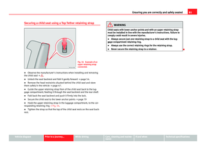
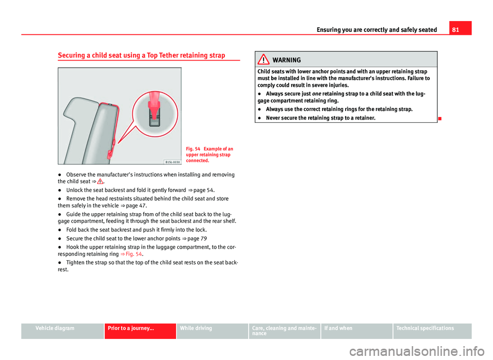
Securing a child seat using a Top Tether retaining strap
Fig. 54 Example of an
upper retaining strap
connected.
● Observe the manufacturer's instructions when installing and removing
the child seat ⇒
.
● Unlock the seat backrest and fold it gently forward
⇒ page 54.
● Remove the head restraints situated behind the child seat and store
them safely in the vehicle ⇒ page 47.
● Guide the upper retaining strap from of the child seat back to the lug-
gage compartment, feeding it through the seat backrest and the rear shelf.
● Fold back the seat backrest and push it firmly into the lock.
● Secure the child seat to the lower anchor points
⇒ page 79
● Hook the upper retaining strap in the luggage compartment, to the cor-
responding retaining ring ⇒ Fig. 54.
● Tighten the strap so that the top of the child seat rests on the seat back-
rest.
WARNING
Child seats with lower anchor points and with an upper retaining strap
must be installed in line with the manufacturer's instructions. Failure to
comply could result in severe injuries.
● Always secure just one retaining strap to a child seat with the lug-
gage compartment retaining ring.
● Always use the correct retaining rings for the retaining strap.
● Never secure the retaining strap to a retainer.
Vehicle diagramPrior to a journey...While drivingCare, cleaning and mainte-
nanceIf and whenTechnical specifications
Page 84 of 306

82Lights and visibility
Lights and visibility
Lights Introduction
The legal requirements regarding the use of vehicle lights in each country
must be observed.
The driver is personally responsible for the correct use and adjustment of
the lights in all situations.
Additional information and warnings:
● Exterior detail ⇒ page 6
● SEAT information system ⇒ page 22
● Changing bulbs ⇒ page 266
WARNING
If the headlights are set too high and the main beam is not used correct-
ly, there is a risk of dazzling or distracting other road users. This could
result in a serious accident.
● Always make sure that the headlights are correctly adjusted.
● Never use the main beam or flashed headlamps as this could dazzle
other drivers.
Control lamps
lights upPossible causeSolution
Rear fog light switched on.⇒ page 84.
Fog lights switched on⇒ page 84.
Left or right turn signal.
The control lamp flashes twice
as fast when a vehicle turn sig-
nal is faulty.If necessary, check the vehicle
lighting.
Main beam on or flasher on.⇒ page 83.
Several warning and control lamps should light up for a few seconds when
the ignition is switched on, signalling that the function is being verified.
They will switch off after a few seconds.
WARNING
If the warning lamps are ignored, the vehicle may stall in traffic, or may
cause accidents and severe injuries.
● Never ignore the warning lamps.
● Stop the vehicle safely as soon as possible.
● Park the vehicle at a suitable distance away from the traffic ensuring
that the exhaust system is not in contact with inflammable material, for
example, dry grass, fuel, oil, etc.
● A faulty vehicle represents a risk of accident for the driver and for oth-
er road users. If necessary, switch on the hazard warning lamps and put
out the warning triangle to advise other drivers.
Page 85 of 306

83
Lights and visibility
CAUTION
Failure to heed the warning lamps when they appear may result in faults in
the vehicle.
Turn signal and headlight lever
Fig. 55 Turn signal and
main beam lever in their
initial position
Move the lever to the required position:
Right turn signal.
Left turn signal.
Switching on main beam ⇒
. When the main beam is switched on,
the warning lamp is switched on in the instrument panel.
Switch on the flasher or switch off the main beam headlights. The flash-
ed beam comes on if the lever is pressed. The warning lamp will
light up during this process.
123
4
Push the lever all the way down to turn off the corresponding function.
Convenience turn signals
For the convenience turn signals, move the lever as far as possible upwards
or downwards and release the lever. The turn signal will flash 3 times.
The convenience indicators can be deactivated at a Specialised workshop.
WARNING
Incorrect use of the headlights may cause accidents and serious injury,
as the main beam may distract or dazzle other drivers.
Note
The turn signal only works when the ignition is switched on. The hazard
warning lights also work when the ignition is switched off ⇒ page 241.
Note
If any of both turn signals fails, the warning lamp will start flashing twice
faster than normal.
Note
The main beam headlights can only be switched on if the dipped beam
headlights are already on.
Vehicle diagramPrior to a journey...While drivingCare, cleaning and mainte-
nanceIf and whenTechnical specifications
Page 86 of 306

84Lights and visibility
Turning on and off lights
Fig. 56 Next to the steering wheel: diagram of some of
the types of light switch
The legal requirements regarding the use of vehicle lights in each country
must be observed.
Turn the light switch to the required position ⇒ Fig. 56: if the ignition is switched offwhen the ignition is on
Fog lights, dipped beam and
side lights off.Lights off, daytime driving light
on.
Side light on.Side light on.
Dipped beam off; if necessary,
the side light comes on for a
time.Dipped beam switched on.
Fog lights*
The control lamp appears on the fog lights control connected. ●
Switching on the fog lights : Turn the switch to position or pull out
to the first stop.
● Switching on the rear fog light : turn the light switch to position o
pull out to the maximum.
● To switch off the fog lights, press the light switch or turn it to position .
Audible warnings to advise the driver that the lights have not been
switched off
If the key is not in the ignition and the driver door is open, an audible warn-
ing signal is heard in the following cases: This is a reminder to turn off the
lights.
● When the light switch is in position .
Page 87 of 306

85
Lights and visibility
WARNING
The side lights or daytime driving lights are not bright enough to illumi-
nate the road ahead and to ensure that other road users are able to see
you.
● Always use your dipped beam head lights if it is raining or if visibility
is poor.
Lights and visibility: functions
Parking light remains on both sides
If when switching off the ignition, the light control remains in the posi-
tion and the vehicle is closed from outside, both headlights, in addition
to the side lights and the rear lights will light up.
Daytime driving light
The daytime driving light consists of individual lights in the front head-
lamps.
When the daytime driving light is switched on, only the individual lights
come on ⇒
.
The daytime lights are switched on each time the ignition is turned on if the
light switch is in position .
Switching the daytime driving light on and off
To switch the daytime driving light on or off, it is necessary to fit or remove
the corresponding fuse. Ask for professional assistance for this.
WARNING
If the road is not well-lit and the vehicle is not clearly visible to other
drivers, there is a risk of accident.
● Never use the daytime driving light if the road is not well-lit as a re-
sult of the weather conditions and poor visibility. The daytime driving
lights are not bright enough to illuminate the road ahead and to ensure
that other road users are able to see you.
● The rear lights do not come on with the daytime driving light. A vehi-
cle which does not have the rear lights on may not be visible to other
drivers in the darkness, if it is raining or in conditions of poor visibility.
Note
The headlights, rear lights and turn signals may mist up temporarily on the
inside in cool or damp weather. This is normal and in no way effects the
useful life of the vehicle lighting system.
Adjusting the headlights
In those countries where vehicles drive on the other side of the road to the
home country, the asymmetric dipped beam may dazzle drivers of oncom-
ing vehicles.
For this reason, stickers may need to be used to cover the headlights when
driving abroad. For further information, please refer to a specialised work-
shop. SEAT recommends visiting a Technical Service.
Note
The use of stickers to cover headlights is only permitted over a short period.
To modify the direction of the headlamps more permanently, please take
the vehicle to a specialised workshop. SEAT recommends visiting a Techni-
cal Service.
Vehicle diagramPrior to a journey...While drivingCare, cleaning and mainte-
nanceIf and whenTechnical specifications
Page 88 of 306

86Lights and visibility
Headlight range control, lighting of instruments and
controls
Fig. 57 Next to the
steering wheel: Head-
light range control
Headlamp height adjustment
The headlight range control ⇒ Fig. 57 is modified according to the value of
the headlight beam and the vehicle load status. This offers the driver opti-
mum visibility and the headlights do not dazzle oncoming drivers ⇒
.
The headlights can only be adjusted when the dipped beam is switched on.
To reset, turn switch ⇒ Fig. 57:ValueVehicle load status a)–Two front occupants, luggage compartment empty1All seats occupied, luggage compartment empty2All seats occupied, luggage compartment full3Driver only, luggage compartment fulla)
If the vehicle load does not correspond to those shown in the table, it is possible to select
intermediary positions. Instrument and switch lighting
When the side lights or dipped beam headlights are switched on, the light-
ing for instruments and controls lights up at a constant brightness.
WARNING
Heavy objects in the vehicle may mean that the headlights dazzle and
distract other drivers. This could result in a serious accident.
● Adjust the light beam to the vehicle load status so that it does not
blind other drivers.
Reading light
Button/ Switcheffect
Switching off the reading light.
Switching on the reading light.
Switches door contact control on (central position).
The reading light comes on automatically when the vehicle is un-
locked, a door is opened or the key is removed from the ignition.
The light goes off a few seconds after all the doors are closed,
the vehicle is locked or the ignition is switched on.
Note
The reading lights go out when the vehicle is locked, or a few minutes after
the key is removed from the ignition. This prevents the battery from dis-
charging.