2013 MERCEDES-BENZ GLA SUV ignition
[x] Cancel search: ignitionPage 185 of 401

If you leave the vehicle parked up for longer
than six weeks, the vehicle may suffer dam-
age as a result of lack of use.
X Visit a qualified specialist workshop and
seek advice.
i You can obtain information about trickle
chargers from a qualified specialist work-
shop. Driving tips
General notes
G
WARNING
If you switch off the ignition while driving,
safety-relevant functions are only available
with limitations, or not at all. This could affect, for example, the power steering and the brake
boosting effect. You will require considerably
more effort to steer and brake. There is a risk of an accident.
Do not switch off the ignition while driving. ECO display
The ECO display provides feedback on how
economical your driving characteristics are.
The ECO display assists you in achieving the
most economical driving style for the selec-
ted settings and prevailing conditions. Con-
sumption can be significantly influenced by
your driving style. Example: ECO display
The ECO display consists of three bars:
R Acceleration Acceleration
R Constant
Constant
R Coasting
Coasting The percentage count is the mean value of the
three bar values. The three bars and the mean
value begin at the value of 50 %. A higher per- centage count indicates a more economical
driving style.
The ECO display does not indicate the actual
fuel consumption. A fixed percentage count
in the ECO display does not indicate a fixed
consumption.
In addition to driving style, the consumption is
affected by many other factors, such as:
R load
R tyre pressure
R cold start
R choice of route
R the use of electrical consumers
These factors are not included in the ECO dis-
play.
The evaluation of your driving style takes the
following three categories into consideration:
R Acceleration Acceleration (evaluation of all accelera-
tion processes):
- The bar fills up: moderate acceleration,
especially at higher speeds
- The bar empties: sporty acceleration
R Constant Constant (assessment of driving behav-
iour at all times):
- The bar fills up: constant speed and
avoidance of unnecessary acceleration
and deceleration
- The bar empties: fluctuations in speed
R Coasting Coasting (assessment of all deceleration
processes):
- The bar fills up: anticipatory driving,
keeping your distance and early release
of the accelerator. The vehicle can coast
without use of the brakes
- The bar empties: frequent braking
i An economical driving style involves driv-
ing at a moderate engine speed.
To achieve a higher value in the categories
Acceleration
Acceleration andConstant Constant: 182
Driving tipsDriving and parking
Page 210 of 401
PARKTRONIC is activated automatically if
you:
R switch on the ignition
R shift to position D,Ror Non vehicles with
automatic transmission
R release the electric parking brake
PARKTRONIC is deactivated at speeds above
18 km/h. It is reactivated at lower speeds.
Range of the sensors General notes
PARKTRONIC does not take into account
obstacles located:
R below the detection range, e.g. persons,
animals or objects
R above the detection range, e.g. overhang-
ing loads, tail sections or loading ramps of
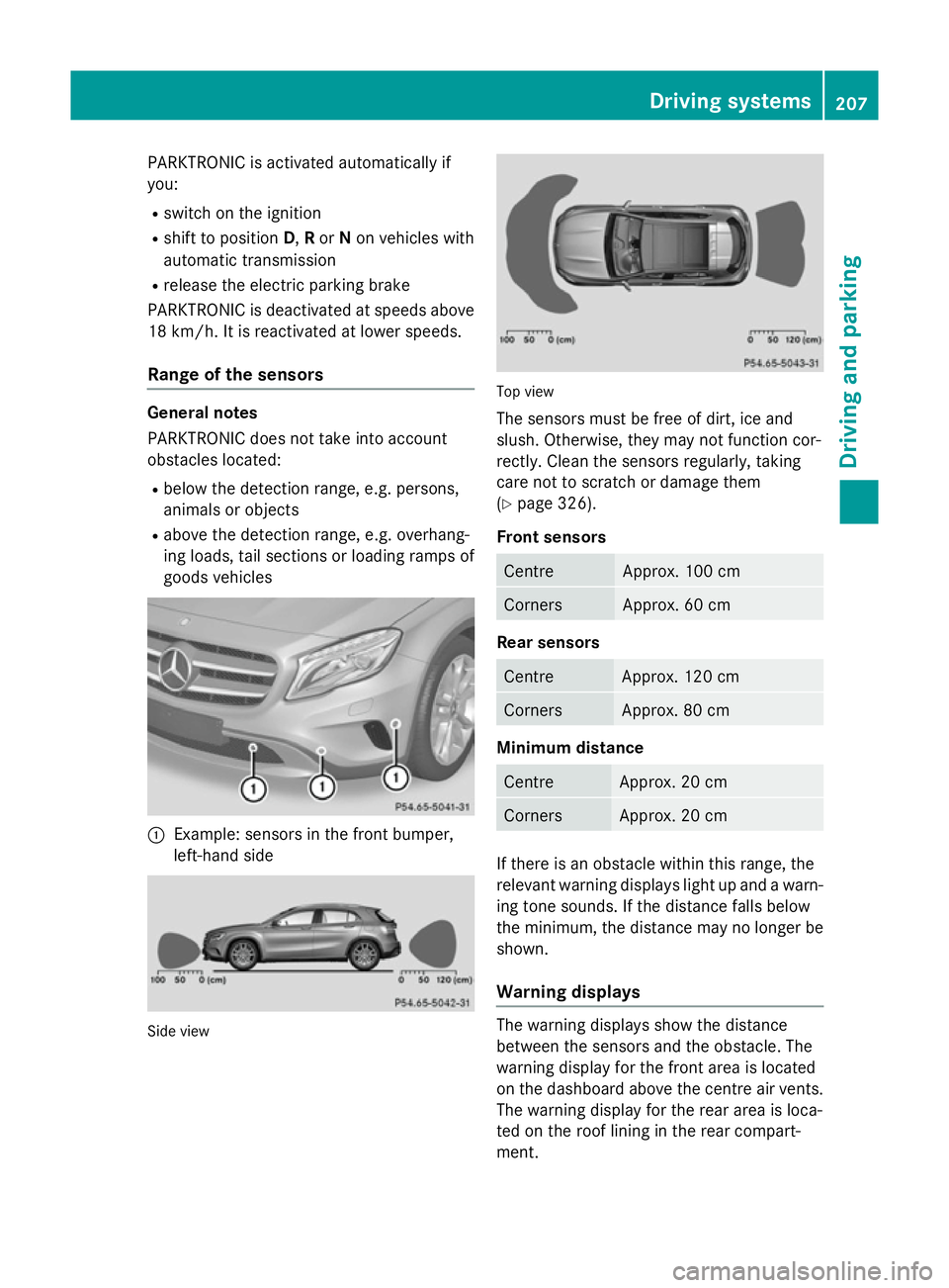
goods vehicles :
Example: sensors in the front bumper,
left-hand side Side view Top view
The sensors must be free of dirt, ice and
slush. Otherwise, they may not function cor-
rectly. Clean the sensors regularly, taking
care not to scratch or damage them
(Y page 326).
Front sensors Centre Approx. 100 cm
Corners Approx. 60 cm
Rear sensors
Centre Approx. 120 cm
Corners Approx. 80 cm
Minimum distance
Centre Approx. 20 cm
Corners Approx. 20 cm
If there is an obstacle within this range, the
relevant warning displays light up and a warn- ing tone sounds. If the distance falls below
the minimum, the distance may no longer be
shown.
Warning displays The warning displays show the distance
between the sensors and the obstacle. The
warning display for the front area is located
on the dashboard above the centre air vents.
The warning display for the rear area is loca-
ted on the roof lining in the rear compart-
ment. Driving systems
207Driving and parking Z
Page 211 of 401

Warning display for the front area
:
Segments on the left-hand side of the
vehicle
; Segments on the right-hand side of the
vehicle
= Segments showing operational readiness
The warning display for each side of the vehi-
cle is divided into five yellow and two red seg- ments. PARKTRONIC is operational if yellow
segments showing operational readiness =
light up.
The gear lever position or the transmission
position of the automatic transmission and
the direction in which the vehicle is rolling
determine which warning display is active
when the engine is running.
Manual transmission: Gear lever posi-
tion Warning display
Forward gear
or
Neutral
Front area activated
Reverse gear
or
the vehicle is rolling backwards Rear and front areas
activated Automatic transmission:
Transmission
position Warning display
D
Front area activated
R,
Nor the vehicle
is rolling back-
wards Rear and front areas
activated
P
No areas activated
One or more segments light up as the vehicle
approaches an obstacle, depending on the
vehicle's distance from the obstacle.
From the:
R sixth segment onwards, you will hear an
intermittent warning tone for approx-
imately two seconds.
R seventh segment onwards, you will hear a
warning tone for approximately two sec-
onds. This indicates that you have now
reached the minimum distance.
Deactivating/activating PARKTRONIC :
Indicator lamp
; Deactivating/activating PARKTRONIC
If indicator lamp :lights up, PARKTRONIC is
deactivated.
i PARKTRONIC is automatically activated
when you turn the key to position 2in the
ignition lock. 208
Driving systemsDriving and parking
Page 213 of 401
Problems with PARKTRONIC
Problem
Possible causes/consequences and
M
MSolutions Only the red segments
in the PARKTRONIC
warning displays are lit.
You also hear a warning
tone for approximately
two seconds.
PARKTRONIC is then
deactivated and the
indicator lamp on the
PARKTRONIC button
lights up. PARKTRONIC has malfunctioned and has been deactivated.
X If problems persist, have PARKTRONIC checked at a qualified
specialist workshop. Only the red segments
in the PARKTRONIC
warning displays are lit.
PARKTRONIC is then
deactivated. The PARKTRONIC sensors are dirty or there is interference.
X Clean the PARKTRONIC sensors (Y page 326).
X Switch the ignition back on. The problem may be caused by an external source of radio or
ultrasound waves.
X See if PARKTRONIC functions in a different location. Active Parking Assist
General notes Active Parking Assist is an electronic parking
aid with ultrasound. It measures the road on
both sides of the vehicle. A parking symbol
indicates a suitable parking space. Active
steering intervention and brake application
can assist you during parking and when exit-
ing a parking space. You may also use PARK- TRONIC (Y page 206).
i The active braking application is only
available on vehicles with automatic trans- mission.
Important safety notes Active Parking Assist is only an aid. It is not a
substitute for your attention to the immediate surroundings. The responsibility for safe
manoeuvring and parking remains with you. Make sure that no persons, animals or
objects are in the manoeuvring range.
When PARKTRONIC is switched off, Active
Parking Assist is also unavailable. G
WARNING
While parking or pulling out of a parking
space, the vehicle swings out and can drive
onto areas of the oncoming lane. This could
cause you to collide with other road users.
There is a risk of an accident.
Pay attention to other road users. Stop the
vehicle if necessary or cancel the Active Park- ing Assist parking procedure.
! If unavoidable, you should drive over
obstacles such as kerbs slowly and not at a
sharp angle. Otherwise, you may damage
the wheels or tyres. 210
Driving systemsDriving and parking
Page 219 of 401
The reversing camera is protected from rain-
drops and dust by means of a flap. When the
reversing camera is activated, this flap opens. Only once the manoeuvring process has been completed and the reversing camera has
switched off does the flap close again. For
technical reasons, the flap may remain open
briefly after the reversing camera has been
deactivated. If you switch off the engine, the
flap will also close.
i The text of messages shown in the
COMAND display depends on the language
setting. The following are examples of
reversing camera messages in the
COMAND display.
Observe the notes on cleaning (Y page 327).
Important safety notes The reversing camera is only an aid. It is not a
substitute for your attention to the immediate
surroundings. The responsibility for safe
manoeuvring and parking remains with you.
Make sure that there are no persons, animals
or objects in range while manoeuvring and
parking.
Under the following circumstances, the
reversing camera will not function, or will
function in a limited manner:
R if the tailgate is open
R in heavy rain, snow or fog
R at night or in very dark places
R if the camera is exposed to very bright light
R if the area is lit by fluorescent light or LED
lighting (the display may flicker)
R if there is a sudden change in temperature,
e.g. when driving into a heated garage in
winter
R if the camera lens is dirty or obstructed
R if the rear of your vehicle is damaged. In this
case, have the camera position and setting checked at a qualified specialist workshop.
The field of vision and other functions of the
reversing camera may be restricted due to additional accessories on the rear of the vehi-
cle (e.g. licence plate holder, bicycle rack).
Activating/deactivating the reversing
camera X
To activate: make sure that the key is in
position 2in the ignition lock.
X Make sure that the "Activation by R gear"
function is selected in the Audio system/
COMAND Online; see the separate operat-
ing instructions.
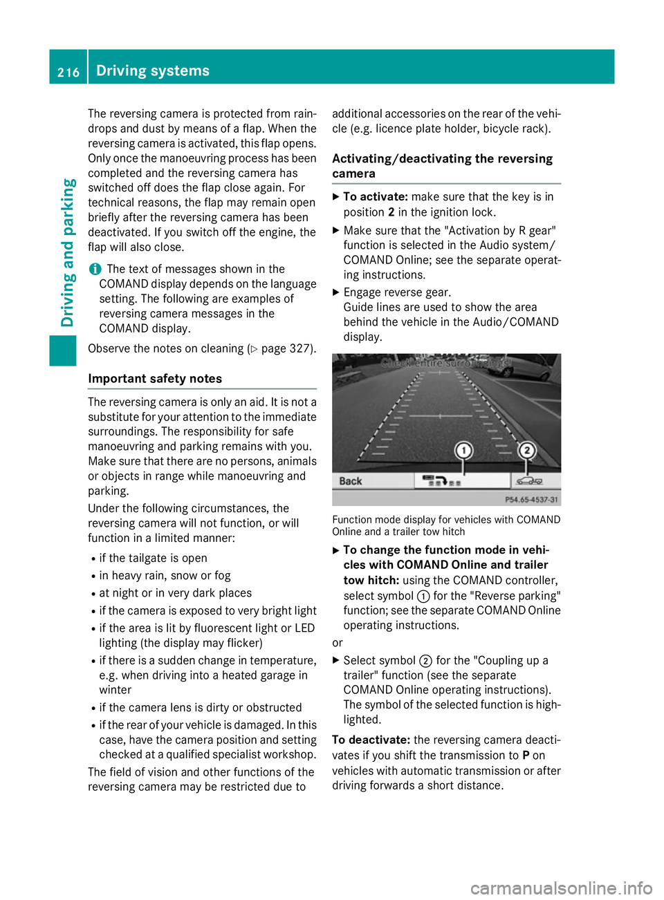
X Engage reverse gear.
Guide lines are used to show the area
behind the vehicle in the Audio/COMAND
display. Function mode display for vehicles with COMAND
Online and a trailer tow hitch
X To change the function mode in vehi-
cles with COMAND Online and trailer
tow hitch: using the COMAND controller,
select symbol :for the "Reverse parking"
function; see the separate COMAND Online
operating instructions.
or
X Select symbol ;for the "Coupling up a
trailer" function (see the separate
COMAND Online operating instructions).
The symbol of the selected function is high-
lighted.
To deactivate: the reversing camera deacti-
vates if you shift the transmission to Pon
vehicles with automatic transmission or after driving forwards a short distance. 216
Driving systemsDriving and parking
Page 227 of 401
Activating Blind Spot Assist
X Make sure that Blind Spot Assist is activa-
ted in the on-board computer
(Y page 245).
X Turn the key to position 2in the ignition
lock.
Warning lamps :in the exterior mirrors
light up red for approximately 1.5 seconds
and then turn yellow.
Towing a trailer
If you attach a trailer, make sure that you have
correctly established the electrical connec-
tion. This can be accomplished by checking
the trailer lighting. Blind Spot Assist is then
deactivated. The indicator lamp lights up yel-
low in the exterior mirrors and the Blind
Blind
Spot Assist currently unavailable
Spot Assist currently unavailable
See Owner's Manual
See Owner's Manual message appears in
the multifunction display.
i You can deactivate the indicator lamps in
the exterior mirrors.
To do so, deactivate Blind Spot Assist if:
R the key is in position 2in the ignition lock
R the engine is not running
R the electrical connection to the trailer
has been established
Lane Keeping Assist General notes
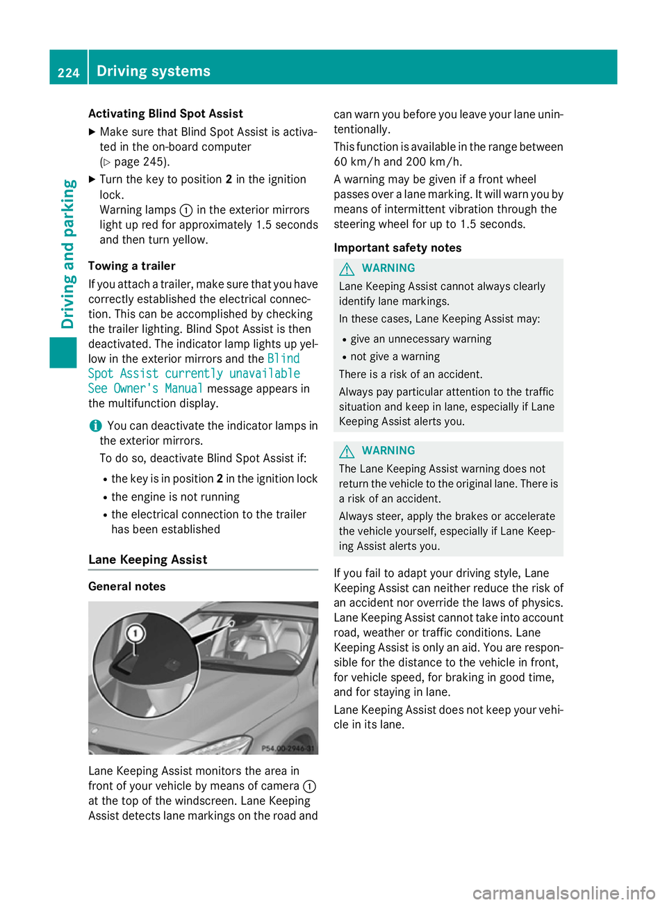
Lane Keeping Assist monitors the area in
front of your vehicle by means of camera :
at the top of the windscreen. Lane Keeping
Assist detects lane markings on the road and can warn you before you leave your lane unin-
tentionally.
This function is available in the range between
60 km/h and 200 km/h.
A warning may be given if a front wheel
passes over a lane marking. It will warn you by means of intermittent vibration through the
steering wheel for up to 1.5 seconds.
Important safety notes G
WARNING
Lane Keeping Assist cannot always clearly
identify lane markings.
In these cases, Lane Keeping Assist may:
R give an unnecessary warning
R not give a warning
There is a risk of an accident.
Always pay particular attention to the traffic
situation and keep in lane, especially if Lane
Keeping Assist alerts you. G
WARNING
The Lane Keeping Assist warning does not
return the vehicle to the original lane. There is a risk of an accident.
Always steer, apply the brakes or accelerate
the vehicle yourself, especially if Lane Keep-
ing Assist alerts you.
If you fail to adapt your driving style, Lane
Keeping Assist can neither reduce the risk of
an accident nor override the laws of physics. Lane Keeping Assist cannot take into account
road, weather or traffic conditions. Lane
Keeping Assist is only an aid. You are respon- sible for the distance to the vehicle in front,
for vehicle speed, for braking in good time,
and for staying in lane.
Lane Keeping Assist does not keep your vehi-
cle in its lane. 224
Driving systemsDriving and pa
rking
Page 233 of 401
X
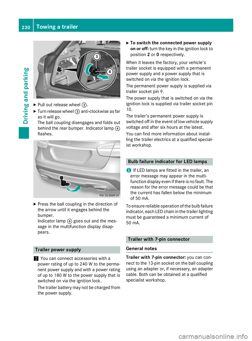
Pull out release wheel =.
X Turn release wheel =anti-clockwise as far
as it will go.
The ball coupling disengages and folds out
behind the rear bumper. Indicator lamp ?
flashes. X
Press the ball coupling in the direction of
the arrow until it engages behind the
bumper.
Indicator lamp ?goes out and the mes-
sage in the multifunction display disap-
pears. Trailer power supply
! You can connect accessories with a
power rating of up to 240 W to the perma-
nent power supply and with a power rating of up to 180 W to the power supply that is
switched on via the ignition lock.
The trailer battery may not be charged from the power supply. X
To switch the connected power supply
on or off: turn the key in the ignition lock to
position 2or 0respectively.
When it leaves the factory, your vehicle's
trailer socket is equipped with a permanent
power supply and a power supply that is
switched on via the ignition lock.
The permanent power supply is supplied via
trailer socket pin 9.
The power supply that is switched on via the
ignition lock is supplied via trailer socket pin
10.
The trailer's permanent power supply is
switched off in the event of low vehicle supply
voltage and after six hours at the latest.
You can find more information about instal-
ling the trailer electrics at a qualified special- ist workshop. Bulb failure indicator for LED lamps
i If LED lamps are fitted in the trailer, an
error message may appear in the multi-
function display even if there is no fault. The
reason for the error message could be that
the current has fallen below the minimum
of 50 mA.
To ensure reliable operation of the bulb failure indicator, each LED chain in the trailer lighting
must be guaranteed a minimum current of
50 mA. Trailer with 7-pin connector
General notes Trailer with 7-pin connector:
you can con-
nect to the 13-pin socket on the ball coupling using an adapter or, if necessary, an adapter
cable. Both can be obtained at a qualified
specialist workshop. 230
Towing a trailerDriving and parking
Page 238 of 401
At high outside temperatures and when driv-
ing uphill, the coolant temperature may rise
to the end of the scale. Rev counter
! Do not drive in the overrevving range.
Doing so will damage the engine.
The red band in the rev counter indicates the
engine's overrevving range.
The fuel supply is interrupted to protect the
engine when the red band is reached. Outside temperature display
You should pay special attention to road con-
ditions when temperatures are around the
freezing point.
The outside temperature display is in the mul- tifunction display.
Changes in the outside temperature are dis-
played after a short delay. Speedometer with segments
The speedometer is divided into segments on
vehicles with DISTRONIC PLUS.
The segments in the speedometer indicate
which speed range is available.
R Cruise control activated (Y page 188):
The segments light up from the stored
speed to the maximum speed.
R Variable SPEEDTRONIC activated
(Y page 192):
The segments light up from the start of the
scale to the selected limit speed.
R DISTRONIC PLUS activated (Y page 193):
One or two segments in the set speed
range light up.
R DISTRONIC PLUS detects a vehicle in front:
The segments between the speed of the
vehicle in front and the stored speed light
up. Operating the on-board computer
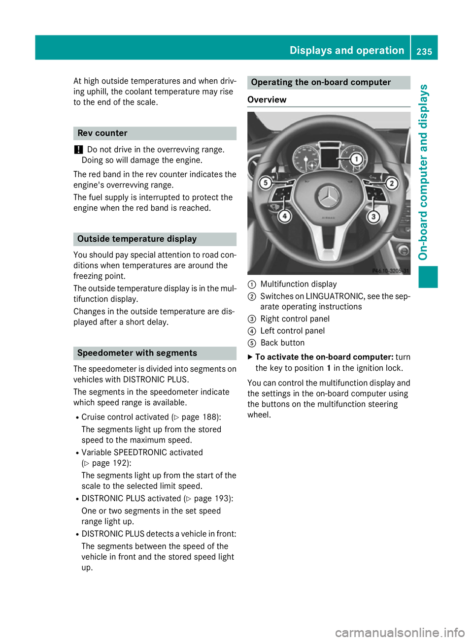
Overview :
Multifunction display
; Switches on LINGUATRONIC, see the sep-
arate operating instructions
= Right control panel
? Left control panel
A Back button
X To activate the on-board computer: turn
the key to position 1in the ignition lock.
You can control the multifunction display and
the settings in the on-board computer using
the buttons on the multifunction steering
wheel. Displays and operation
235On-board computer and displays Z