2013 MERCEDES-BENZ GLA SUV service interval
[x] Cancel search: service intervalPage 8 of 401

Assistance display (on-board com-
puter)
.................................................. 243
Assistance menu (on-board com-
puter) .................................................. 243
ASSYST PLUS
Displaying a service message ........ 322
Hiding a service message .............. 322
Notes ............................................ .321
Resetting the service interval dis-
play ................................................ 322
Service message ............................ 321
Special service requirements ......... 322
ATA (Anti-Theft Alarm system)
Activating/deactivating ................... 81
Function .......................................... .81
Interior motion sensor .....................82
Switching off the alarm .................... 81
Tow-away protectio n ........................81
ATTENTION ASSIST
Activating/deactivating ................. 244
Display message ............................ 275
Function/notes ............................ .220
Audio menu (on-board computer) .... 240
Authorised workshop
see Qualified specialist workshop
AUTO lights
Display message ............................ 271
see Lights
Automatic engine start (ECO start/
stop function) ................................... .163
Automatic engine switch-off (ECO
start/stop function) .......................... 162
Automatic front-passenger front
airbag deactivation system
Display message ............................ 267
Operation ......................................... 52
Problems ......................................... 56
System self-test ............................... 54
Automatic headlamp mode .............. 121
Automatic transmission
Accelerator pedal position ............. 170
Automatic drive program .............. .172
Changing gear ............................... 170
DIRECT SELECT lever ..................... 167
Drive program displa y.................... 168
Driving tips .................................... 170
Emergency running mode .............. 175 Engaging drive position .................. 169
Engaging neutral ............................ 169
Engaging park position (AMG vehi-
cles) ............................................... 169
Engaging reverse gear ................... 169
Engaging the park position ............ 168
Holding the vehicle stationary on
uphill gradients .............................. 170
Kickdown ....................................... 170
Manual drive progra m.................... 172
Overview ........................................ 167
Problem (fault) ............................... 175
Program selector button ................ 171
Pulling away ................................... 160
Selector lever ................................ 169
Starting the engine ........................ 160
Steering wheel gearshift paddle s... 171
Trailer towing ................................. 171
Transmission position dis-
play ........................................ 168, 169
Transmission positions .................. 169
Automatic transmission emer-
gency running mode ......................... 175
Auxiliary heating
Activating/deactivating ................. 150
Activating/deactivating (on the
centre console ).............................. 151
Display message ............................ 286
Important safety notes .................. 150
Problem (display message) ............ 154
Remote control .............................. 151
Setting ........................................... 249
Setting the departure time ............. 152
Auxiliary ventilation
Activating/deactivating ................. 150
Activating/deactivating (on the
centre console ).............................. 151
Problem (display message) ............ 154
Remote control .............................. 151
Axle load, permissible (trailer tow-
ing) ...................................................... 394 B
Bag hook ............................................ 306
Ball coupling
Folding in ....................................... 229
Folding out ..................................... 228 Index
5
Page 25 of 401

Protection of the environment
General notes
H
Environmental note
Daimler's declared policy is one of compre-
hensive environmental protection.
Our objectives are to use the natural resour-
ces which form the basis of our existence on
this planet sparingly and in a manner which
takes the requirements of both nature and
humanity into consideration.
You too can help to protect the environment
by operating your vehicle in an environmen-
tally-responsible manner.
Fuel consumption and the rate of engine,
transmission, brake and tyre wear depend on
the following factors:
R operating conditions of your vehicle
R your personal driving style
You can influence both factors. Therefore,
please bear the following in mind:
Operating conditions:
R avoid short trips, as these increase fuel
consumption.
R observe the correct tyre pressure.
R do not carry any unnecessary weight in the
vehicle.
R remove the roof rack once you no longer
need it.
R a regularly serviced vehicle will contribute
to environmental protection. You should
therefore adhere to the service intervals.
R all maintenance work should be carried out
at a qualified specialist workshop.
Personal driving style:
R do not depress the accelerator pedal when
starting the engine.
R do not warm up the engine when the vehicle
is stationary.
R drive carefully and maintain a safe distance
from the vehicle in front.
R avoid frequent, sudden acceleration and
braking. R
change gear in good time and use each gear
only up to Ôof its maximum engine speed.
R switch off the engine in stationary traffic.
R monitor the vehicle's fuel consumption. Returning an end-of-life vehicle
EU countries only:
Mercedes-Benz will take back your old vehicle to dispose of it in an environmentally-respon-sible manner in accordance with the Euro-
pean Union (EU) End of Life Vehicles Direc-
tive.
There is a network of return points and dis-
assembly plants available. You can return
your vehicle to these plants free of charge.
This makes a valuable contribution to the
recycling process and the conservation of
resources.
For further information on recycling old vehi- cles, recovery and the terms of the policy,
visit the Mercedes-Benz homepage. Genuine Mercedes-Benz parts
H
Environmental note
Daimler AG also supplies reconditioned
assemblies and parts which are of the same
quality as new parts. For these, the same war-
ranty applies as for new parts.
! Airbags and seat belt tensioners, as well
as control units and sensors for these
restraint systems, may be installed in the
following areas of your vehicle:
R doors
R door pillars
R door sills
R seats
R dashboard
R instrument cluster
R centre console 22
Introduction
Page 46 of 401

Important safety notes
G
WARNING
If the restraint system is modified, it may no
longer work as intended. The restraint system
may then not perform its intended protective function by failing in an accident or triggering
unexpectedly, for example. There is an
increased risk of injury, possibly even fatal.
Never modify parts of the restraint system. Do not attempt to modify the wiring as well as
electronic components or their software.
If it is necessary to modify an airbag system to
accommodate a person with disabilities, con- tact a Mercedes-Benz Service Centre. Restraint system warning lamp
The functions of the restraint system are
checked after the ignition is switched on and at regular intervals while the engine is run-
ning. Therefore, malfunctions can be detec-
ted in good time.
The restraint system warning lamp in the
instrument cluster lights up when the ignition is switched on. It goes out no later than a few
seconds after the engine is started. The com- ponents of the restraint system are in opera-
tional readiness.
A malfunction has occurred if the 6
restraint system warning lamp:
R does not light up after the ignition is
switched on
R does not go out after a few seconds with
the engine running
R lights up again while the engine is running G
WARNING
If the restraint system is malfunctioning,
restraint system components may be trig-
gered unintentionally or might not be trig-
gered at all in the event of an accident with a high rate of vehicle deceleration. This can
effect belt tensioners or airbags, for example. There is an increased risk of serious or even
fatal injuries.
Have the restraint system checked and
repaired immediately at a qualified specialist
workshop.
PASSENGER AIRBAG indicator lamp
On vehicles with the automatic front-
passenger front airbag deactivation system,
the indicator lamps display the status of the
front-passenger front airbag.
R PASSENGER AIR BAG ON :lights up: the
front-passenger front airbag is enabled. If,
in the case of an accident, all deployment
criteria are met, the front-passenger front
airbag is deployed.
R PASSENGER AIR BAG OFF ;lights up: the
front-passenger front airbag is disabled. It
will then not be deployed in the event of an
accident.
Depending on the person in the front-
passenger seat, the front-passenger front air-
bag must either be disabled or enabled. You
must make sure of this both before and during
a journey.
R Children in a rearward-facing child
restraint system: the PASSENGER AIR
BAG OFF indicator lamp must be lit. The
front-passenger front airbag is disabled.
Always observe the information on the
"Automatic front-passenger front airbag Occupant safety
43Safety Z
Page 141 of 401

Useful information
i This Owner's Manual describes all mod-
els, series and optional equipment for your
vehicle that were available at the time of
going to press. National variations are pos- sible. Note that your vehicle may not be
equipped with all of the functions descri-
bed. This is also the case for systems and
functions relevant to safety.
i Read the information on qualified special-
ist workshops: (Y page 25). Overview of climate control systems
Important safety notes
Observe the settings recommended on the
following pages. The windows could other-
wise mist up.
To prevent the windows from misting up:
R switch off climate control only briefly
R switch on air-recirculation mode only
briefly
R switch on the cooling with air dehumidifi-
cation function
R switch on the "demist windscreen" function
briefly, if required
The air-conditioning system/
THERMOTRONIC automatic climate control
regulates the temperature and the humidity
of the vehicle interior and filters undesirable
substances from the air.
The THERMOTRONIC air-conditioning sys-
tem/automatic climate control can only be
operated when the engine is running. Opti-
mum operation is only achieved with the side windows and panorama sliding sunroof
closed.
The residual heat function can only be acti-
vated or deactivated with the ignition
switched off (Y page 149).
Always keep the ventilation flaps behind the
side panelling clear (Y page 131). Otherwise
the vehicle will not be ventilated correctly. i
Ventilate the vehicle for a brief period
during warm weather, e.g. using the con-
venience opening feature (Y page 99). This
will speed up the cooling process and the
desired interior temperature will be
reached more quickly.
i The integrated filter filters out most par-
ticles of dust and soot and completely fil-
ters out pollen. With THERMOTRONIC auto- matic climate control, gaseous pollutants
and odours will also be reduced. A clogged
filter reduces the amount of air supplied to
the vehicle interior. For this reason, you
should always observe the interval for
replacing the filter, which is specified in the Service Booklet. As this depends on envi-
ronmental conditions, e.g. heavy air pollu-
tion, the interval may be shorter than statedin the Service Booklet.
i It is possible that the residual heat func-
tion may be activated automatically an hour
after the key has been removed in order to
dry the automatic climate control. The vehi- cle is then ventilated for 30 minutes. 138
Overview of climate control systemsClimate control
Page 205 of 401

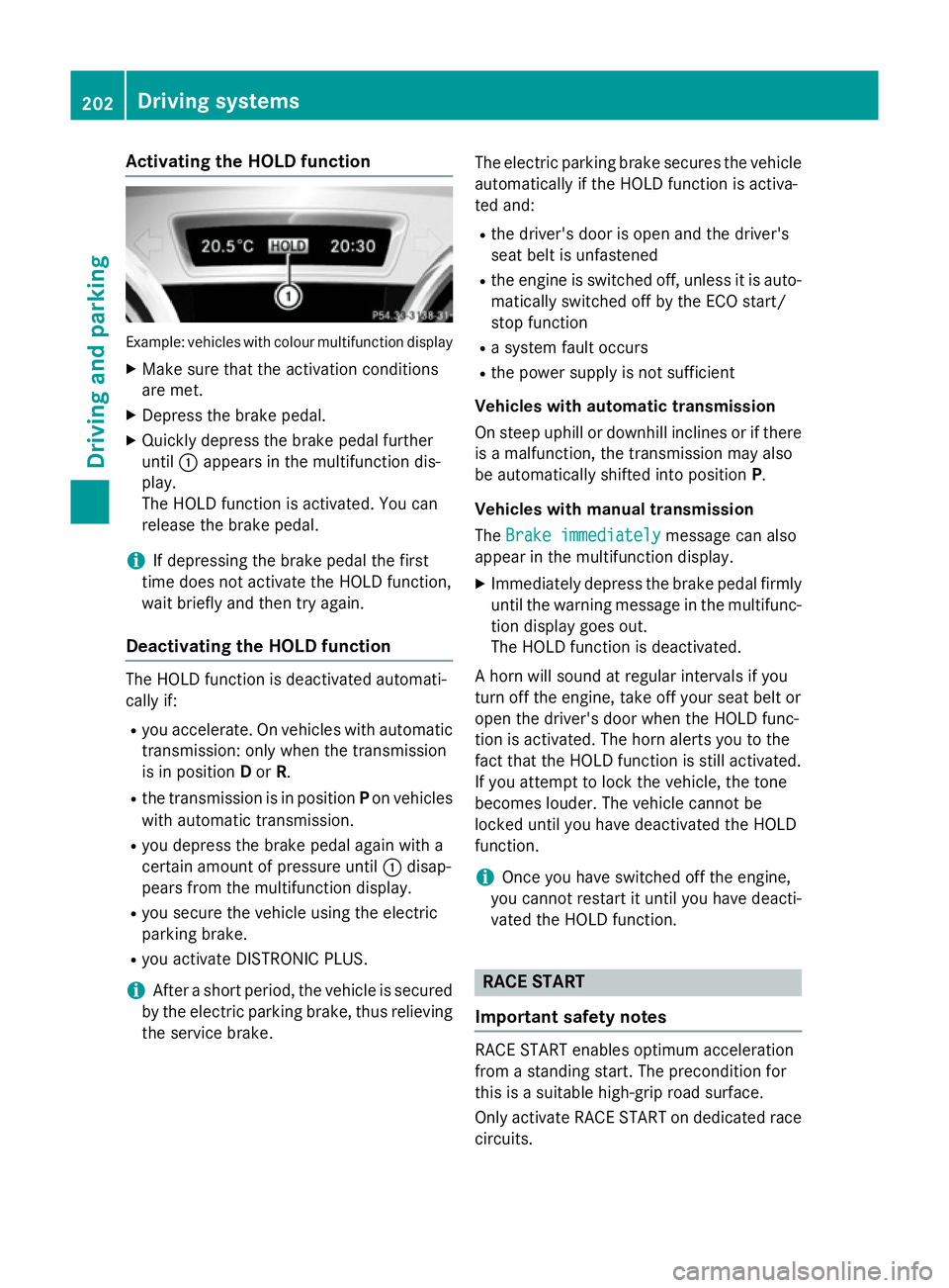
Activating the HOLD function
Example: vehicles with colour multifunction display
X Make sure that the activation conditions
are met.
X Depress the brake pedal.
X Quickly depress the brake pedal further
until :appears in the multifunction dis-
play.
The HOLD function is activated. You can
release the brake pedal.
i If depressing the brake pedal the first
time does not activate the HOLD function,
wait briefly and then try again.
Deactivating the HOLD function The HOLD function is deactivated automati-
cally if:
R you accelerate. On vehicles with automatic
transmission: only when the transmission
is in position Dor R.
R the transmission is in position Pon vehicles
with automatic transmission.
R you depress the brake pedal again with a
certain amount of pressure until :disap-
pears from the multifunction display.
R you secure the vehicle using the electric
parking brake.
R you activate DISTRONIC PLUS.
i After a short period, the vehicle is secured
by the electric parking brake, thus relieving
the service brake. The electric parking brake secures the vehicle
automatically if the HOLD function is activa-
ted and:
R the driver's door is open and the driver's
seat belt is unfastened
R the engine is switched off, unless it is auto-
matically switched off by the ECO start/
stop function
R a system fault occurs
R the power supply is not sufficient
Vehicles with automatic transmission
On steep uphill or downhill inclines or if there
is a malfunction, the transmission may also
be automatically shifted into position P.
Vehicles with manual transmission
The Brake immediately
Brake immediately message can also
appear in the multifunction display.
X Immediately depress the brake pedal firmly
until the warning message in the multifunc-
tion display goes out.
The HOLD function is deactivated.
A horn will sound at regular intervals if you
turn off the engine, take off your seat belt or
open the driver's door when the HOLD func-
tion is activated. The horn alerts you to the
fact that the HOLD function is still activated.
If you attempt to lock the vehicle, the tone
becomes louder. The vehicle cannot be
locked until you have deactivated the HOLD
function.
i Once you have switched off the engine,
you cannot restart it until you have deacti-
vated the HOLD function. RACE START
Important safety notes RACE START enables optimum acceleration
from a standing start. The precondition for
this is a suitable high-grip road surface.
Only activate RACE START on dedicated race
circuits. 202
Driving systemsDriving and pa
rking
Page 249 of 401

Instrument cluster
Selecting the unit of measurement for dis-
tance
You can determine whether the multifunction display shows some messages in miles or kil-
ometres.
X Press the =or; button on the steer-
ing wheel to select the Settings
Settings menu.
X Press the :or9 button to select the
Instrument cluster
Instrument cluster submenu.
X Press ato confirm.
X Press the :or9 button to select the
Display unit Speed-/odometer
Display unit Speed-/odometer func-
tion.
You will see the selected setting: km kmor
miles
miles.
X Press the abutton to save the setting.
The selected unit of measurement for dis-
tance applies to:
R the digital speedometer in the Trip
Tripmenu
R the total distance recorder and the trip
meter
R the trip computer
R the current consumption and the range
R navigation instructions in the Navi
Navi menu
R cruise control
R SPEEDTRONIC
R DISTRONIC PLUS
R ASSYST PLUS service interval display
Switching the additional speedometer
on/off
The Dig. speedometer [mph]
Dig. speedometer [mph] orDig. Dig.
speedometer [km/h]
speedometer [km/h] function (vehicles for
the United Kingdom) allows you to choose
whether the multifunction display in the sta-
tus area always shows the speed in mph
mph or in
km/h
km/h instead of the outside temperature.
X Press the =or; button on the steer-
ing wheel to select the Settings
Settingsmenu.
X Press the :or9 button to select the
Instrument cluster
Instrument cluster submenu.
X Press ato confirm. X
Press the :or9 button to select the
Dig. speedometer [mph]
Dig. speedometer [mph] orDig.
Dig.
speedometer [km/h]
speedometer [km/h] (United Kingdom)
function.
You will see the selected setting: on
on oroff off .
X Press the abutton to save the setting.
Selecting the permanent display function
You can determine whether the multifunction display permanently shows your speed or the
outside temperature.
X Press the =or; button on the steer-
ing wheel to select the Settings
Settingsmenu.
X Press the :or9 button to select the
Instrument cluster
Instrument cluster submenu.
X Press ato confirm.
X Press the :or9 button to select the
Permanent display
Permanent display function.
You will see the selected setting outside
outside
temperature
temperature orDig. speedometer
Dig. speedometer
[mph]
[mph]/Dig. speedometer [km/h] Dig. speedometer [km/h] (vehi-
cles for the United Kingdom).
X Press the abutton to save the setting.
i The speed is displayed in mph or in km/h
(United Kingdom).
Lights Switching the daytime driving lights
on/off
The
Daytime driving lights Daytime driving lights function can
only be switched on with the engine turned
off.
X Press the =or; button on the steer-
ing wheel to select the Settings Settingsmenu.
X Press the :or9 button to select the
Lights
Lights submenu.
X Press ato confirm.
X Press the :or9 button to select the
Daytime driving lights
Daytime driving lights function.
If the Daytime driving lights
Daytime driving lights function
has been switched on, the cone of light and 246
Menus and submenusOn-board computer and displays
Page 323 of 401

Damage to the engine or exhaust system is
caused by the following:
R using engine oils and oil filters that have
not been specifically approved for the
service system
R changing the engine oil and oil filter after
missing the change interval required by
the service system
R using engine oil additives
! Do not add too much oil. Topping up with
too much engine oil can result in damage to
the engine or to the catalytic converter.
Have excess engine oil siphoned off. Example: engine oil filler cap
X Turn cap :anti-clockwise and remove it.
X Top up the engine oil.
If the oil level is at or below the MIN mark on
the oil dipstick, top up with 1.0 lof engine
oil.
X Replace cap :on the filler neck and turn
clockwise.
Make sure that the cap locks securely into place.
X Check the oil level again with the oil dip-
stick (Y page 318).
For further information on engine oil, see
(Y page 388). Checking and adding other service
products
Checking the coolant level G
WARNING
The engine cooling system is under pressure, particularly if the engine is warm. You could
be scalded by hot coolant spraying out when
opening the cap. There is a danger of injury.
Allow the engine to cool before opening the
cap. Wear gloves and protective eyewear
when opening. Slowly turn the cap half a turn
to allow pressure to escape.
! The coolant level must only be checked
and corrected when the engine has cooled
down (coolant temperature under 40 †).
Checking the coolant level when the cool-
ant temperature is over 40 † can lead to
damage to the engine or engine cooling
system. Example
X Park the vehicle on a level surface.
Only check the coolant level if the vehicle is
on a level surface and the engine has
cooled down.
X Turn the key to position 2in the ignition
lock (Y page 159).
X Check the coolant temperature display in
the instrument cluster.
The coolant temperature must be below
40 †.
X Turn the key to position 0in the ignition
lock (Y page 159). 320
Engine compartmentMaintenance and care
Page 324 of 401

X
Slowly turn cap :half a turn anti-clock-
wise to allow excess pressure to escape.
X Turn cap :further anti-clockwise and
remove it.
If the coolant is at the level of marker bar =
in the filler neck when cold, there is enough
coolant in coolant expansion tank ;.
X If necessary, top up with coolant that has
been tested and approved by Mercedes-
Benz.
X Replace cap :and turn it clockwise as far
as it will go.
For further information on coolant, see
(Y page 390).
Topping up the windscreen washer sys-
tem/headlamp cleaning system G
WARNING
Certain components in the engine compart-
ment could be very hot, e.g. the engine, the
radiator and parts of the exhaust system.
There is a risk of injury when accessing the
engine compartment.
As far as possible, allow the engine to cool
down and only touch the following compo-
nents. G
WARNING
Windscreen washer concentrate is highly
flammable. If it comes into contact with hot
engine components or the exhaust system it
could ignite. There is a risk of fire and injury.
Make sure that no windscreen washer con-
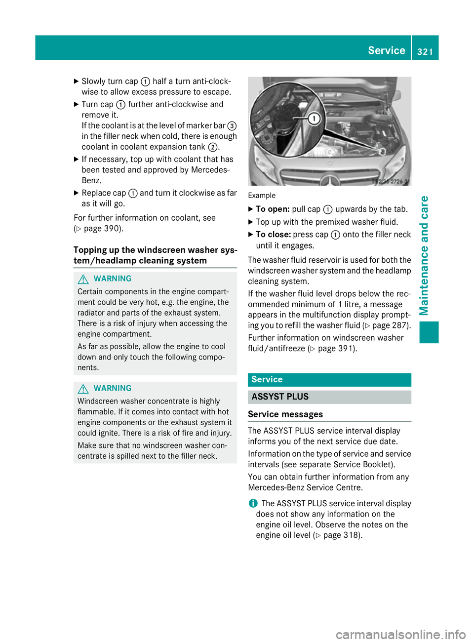
centrate is spilled next to the filler neck. Example
X To open: pull cap:upwards by the tab.
X Top up with the premixed washer fluid.
X To close: press cap :onto the filler neck
until it engages.
The washer fluid reservoir is used for both the
windscreen washer system and the headlamp cleaning system.
If the washer fluid level drops below the rec-
ommended minimum of 1 litre, a message
appears in the multifunction display prompt-
ing you to refill the washer fluid (Y page 287).
Further information on windscreen washer
fluid/antifreeze (Y page 391). Service
ASSYST PLUS
Service messages The ASSYST PLUS service interval display
informs you of the next service due date.
Information on the type of service and service
intervals (see separate Service Booklet).
You can obtain further information from any
Mercedes-Benz Service Centre.
i The ASSYST PLUS service interval display
does not show any information on the
engine oil level. Observe the notes on the
engine oil level (Y page 318). Service
321Maintenance and care Z