Page 6 of 563

Cruise Control 234
Driving Aids 236
Load Carrying 237
Vehicle loading.......................................237
Tailgate............................................244
Towing 249
Trailertowing........................................249
Trailer brake controller-integrated.........................254
Wrecker towing......................................261
Recreational towing...................................263
Driving Hints 264
Economical driving....................................264
Floormats..........................................266
Roadside Emergencies 271
Getting roadside assistance..............................271
Hazard flasher control..................................273
Fuel cut-off switch....................................273
Jump-starting the vehicle...............................274
Customer Assistance 277
Reporting safety defects (U.S. only).......................284
Reporting safety defects (Canada only).....................284
Fuses 285
Changing a fuse......................................285
Fuse specification chart................................286
Upfitter controls......................................294
Table of Contents5
2013 F-250/350/450/550(f23)
Owners Guide gf, 1st Printing
USA(fus)
Page 232 of 563
REAR VIEW CAMERA SYSTEM (IF EQUIPPED)
WARNING:The rear view camera system is a reverse aid
supplement device that still requires the driver to use it in
conjunction with the interior and exterior mirrors for maximum coverage.
WARNING:Objects that are close to either corner of the
bumper or under the bumper, might not be seen on the screen
due to the limited coverage of the camera system.
WARNING:Back up as slow as possible since higher speeds
might limit your reaction time to stop the vehicle.
WARNING:Use caution when turning camera features on or off
while in R (Reverse). Make sure the vehicle is not moving.
The rear view camera system provides a video image of the area behind
the vehicle.
During operation, lines appear in the display which represent your
vehicle’s path and proximity to objects behind the vehicle.
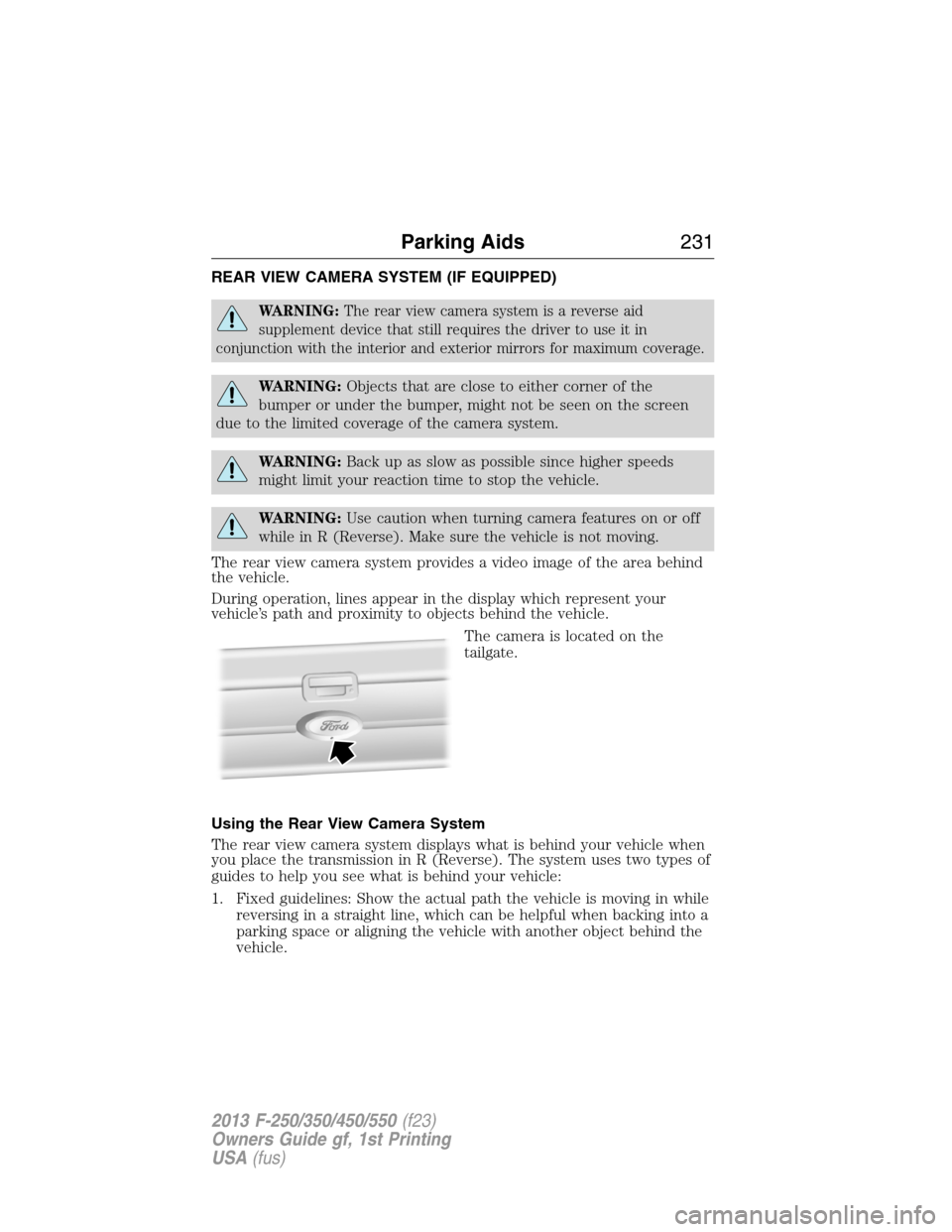
The camera is located on the
tailgate.
Using the Rear View Camera System
The rear view camera system displays what is behind your vehicle when
you place the transmission in R (Reverse). The system uses two types of
guides to help you see what is behind your vehicle:
1. Fixed guidelines: Show the actual path the vehicle is moving in while
reversing in a straight line, which can be helpful when backing into a
parking space or aligning the vehicle with another object behind the
vehicle.
Parking Aids231
2013 F-250/350/450/550(f23)
Owners Guide gf, 1st Printing
USA(fus)
Page 245 of 563
TAILGATE
Tailgate Lock
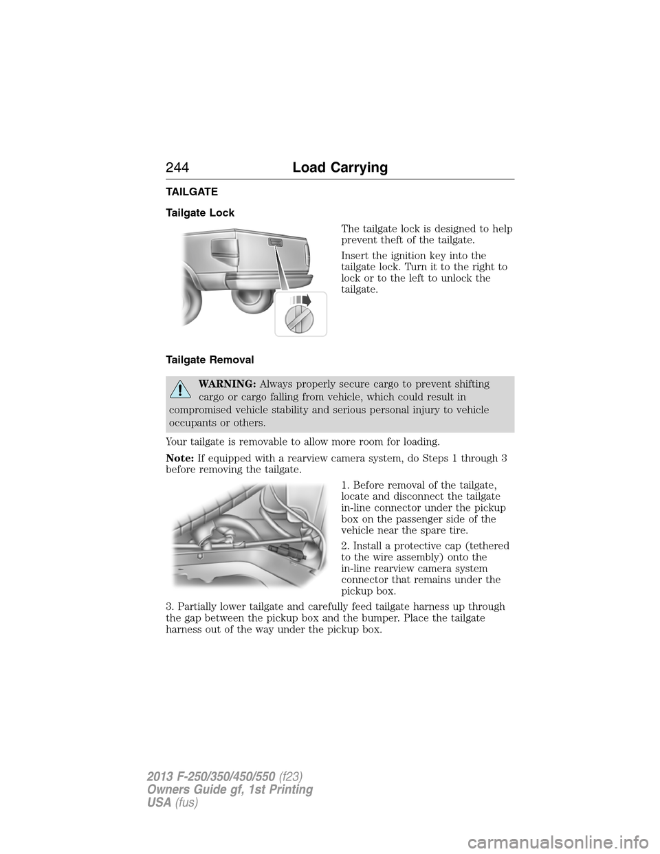
The tailgate lock is designed to help
prevent theft of the tailgate.
Insert the ignition key into the
tailgate lock. Turn it to the right to
lock or to the left to unlock the
tailgate.
Tailgate Removal
WARNING:Always properly secure cargo to prevent shifting
cargo or cargo falling from vehicle, which could result in
compromised vehicle stability and serious personal injury to vehicle
occupants or others.
Your tailgate is removable to allow more room for loading.
Note:If equipped with a rearview camera system, do Steps 1 through 3
before removing the tailgate.
1. Before removal of the tailgate,
locate and disconnect the tailgate
in-line connector under the pickup
box on the passenger side of the
vehicle near the spare tire.
2. Install a protective cap (tethered
to the wire assembly) onto the
in-line rearview camera system
connector that remains under the
pickup box.
3. Partially lower tailgate and carefully feed tailgate harness up through
the gap between the pickup box and the bumper. Place the tailgate
harness out of the way under the pickup box.
244Load Carrying
2013 F-250/350/450/550(f23)
Owners Guide gf, 1st Printing
USA(fus)
Page 246 of 563
4. Lower the tailgate.
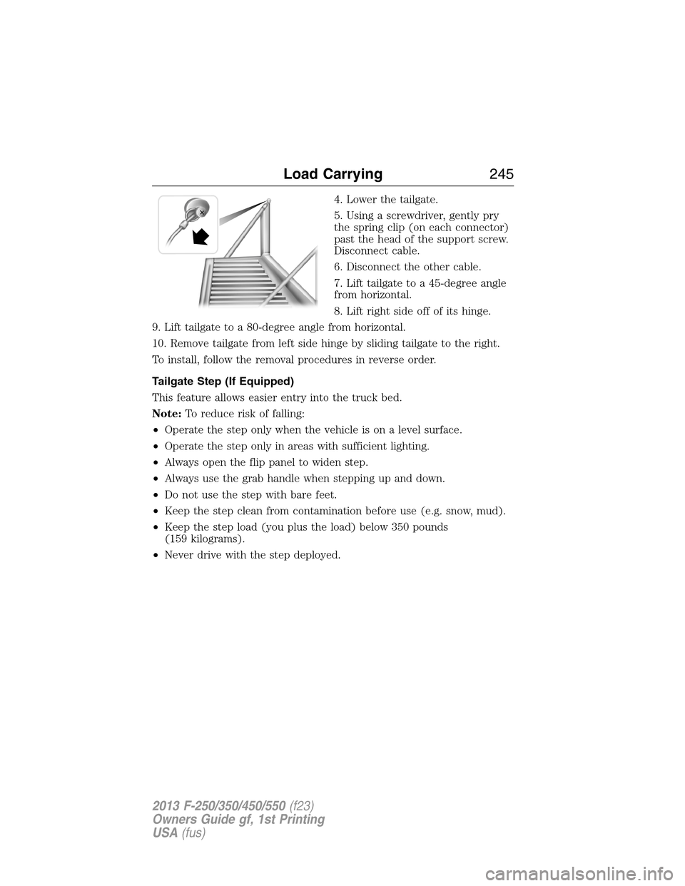
5. Using a screwdriver, gently pry
the spring clip (on each connector)
past the head of the support screw.
Disconnect cable.
6. Disconnect the other cable.
7. Lift tailgate to a 45-degree angle
from horizontal.
8. Lift right side off of its hinge.
9. Lift tailgate to a 80-degree angle from horizontal.
10. Remove tailgate from left side hinge by sliding tailgate to the right.
To install, follow the removal procedures in reverse order.
Tailgate Step (If Equipped)
This feature allows easier entry into the truck bed.
Note:To reduce risk of falling:
•Operate the step only when the vehicle is on a level surface.
•Operate the step only in areas with sufficient lighting.
•Always open the flip panel to widen step.
•Always use the grab handle when stepping up and down.
•Do not use the step with bare feet.
•Keep the step clean from contamination before use (e.g. snow, mud).
•Keep the step load (you plus the load) below 350 pounds
(159 kilograms).
•Never drive with the step deployed.
Load Carrying245
2013 F-250/350/450/550(f23)
Owners Guide gf, 1st Printing
USA(fus)
Page 247 of 563
Opening the Tailgate Step
1. Flip down the tailgate.
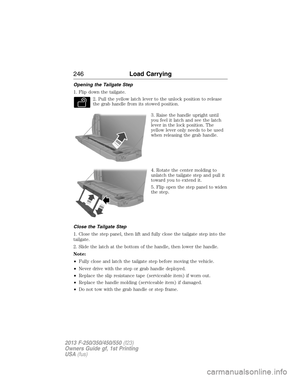
2. Pull the yellow latch lever to the unlock position to release
the grab handle from its stowed position.
3. Raise the handle upright until
you feel it latch and see the latch
lever in the lock position. The
yellow lever only needs to be used
when releasing the grab handle.
4. Rotate the center molding to
unlatch the tailgate step and pull it
toward you to extend it.
5. Flip open the step panel to widen
the step.
Close the Tailgate Step
1. Close the step panel, then lift and fully close the tailgate step into the
tailgate.
2. Slide the latch at the bottom of the handle, then lower the handle.
Note:
•Fully close and latch the tailgate step before moving the vehicle.
•Never drive with the step or grab handle deployed.
•Replace the slip resistance tape (serviceable item) if worn out.
•Replace the handle molding (serviceable item) if damaged.
•Do not tow with the grab handle or step frame.
246Load Carrying
2013 F-250/350/450/550(f23)
Owners Guide gf, 1st Printing
USA(fus)
Page 248 of 563
BED EXTENDER (IF EQUIPPED)
Note:This feature is not intended for off-road usage.
Note:Make sure the locking pins and knobs are fully engaged when the
vehicle is in motion.
Note:Make sure all cargo is secured.
Note:The tailgate load must not exceed 150 pounds (68 kilograms)
when the vehicle is in motion.
Note:The bed extender should always be kept in the grocery mode or
stowed position with the tailgate closed when not being used for the
purpose of restraining cargo in the tailgate mode.
To open the bed extender into tailgate mode:
1. Pull the locking pin toward the
center of the vehicle.
2. Open the latches to release the
panels.
Load Carrying247
2013 F-250/350/450/550(f23)
Owners Guide gf, 1st Printing
USA(fus)
Page 249 of 563
3. Rotate the panels toward the
tailgate.
Repeat Steps 1–3 for the other side of the bed extender.
4. Connect the two panels, then
rotate both knobs a quarter-turn
clockwise to secure the panels.
5. Make sure the latch rod is
inserted into the tailgate hole and
the locking pins on both sides are
engaged into their holes in the
pick-up box.
6. Reverse steps for storage of the
bed extender.
To open the bed extender into
grocery mode, follow Steps 1–4 by
rotating the panels away from the
tailgate. Close the tailgate.
248Load Carrying
2013 F-250/350/450/550(f23)
Owners Guide gf, 1st Printing
USA(fus)
Page 325 of 563
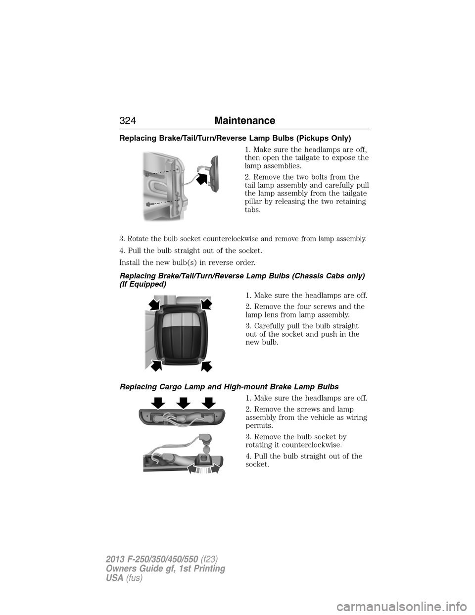
Replacing Brake/Tail/Turn/Reverse Lamp Bulbs (Pickups Only)
1. Make sure the headlamps are off,
then open the tailgate to expose the
lamp assemblies.
2. Remove the two bolts from the
tail lamp assembly and carefully pull
the lamp assembly from the tailgate
pillar by releasing the two retaining
tabs.
3. Rotate the bulb socket counterclockwise and remove from lamp assembly.
4. Pull the bulb straight out of the socket.
Install the new bulb(s) in reverse order.
Replacing Brake/Tail/Turn/Reverse Lamp Bulbs (Chassis Cabs only)
(If Equipped)
1. Make sure the headlamps are off.
2. Remove the four screws and the
lamp lens from lamp assembly.
3. Carefully pull the bulb straight
out of the socket and push in the
new bulb.
Replacing Cargo Lamp and High-mount Brake Lamp Bulbs
1. Make sure the headlamps are off.
2. Remove the screws and lamp
assembly from the vehicle as wiring
permits.
3. Remove the bulb socket by
rotating it counterclockwise.
4. Pull the bulb straight out of the
socket.
324Maintenance
2013 F-250/350/450/550(f23)
Owners Guide gf, 1st Printing
USA(fus)