2013 FORD SUPER DUTY wiring
[x] Cancel search: wiringPage 132 of 563
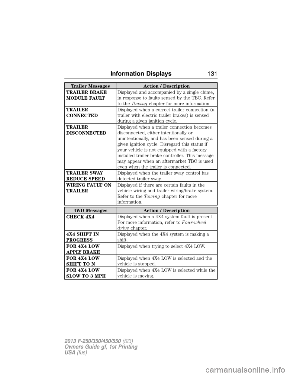
Trailer Messages Action / Description
TRAILER BRAKE
MODULE FAULTDisplayed and accompanied by a single chime,
in response to faults sensed by the TBC. Refer
to theTowingchapter for more information.
TRAILER
CONNECTEDDisplayed when a correct trailer connection (a
trailer with electric trailer brakes) is sensed
during a given ignition cycle.
TRAILER
DISCONNECTEDDisplayed when a trailer connection becomes
disconnected, either intentionally or
unintentionally, and has been sensed during a
given ignition cycle. Disregard this status if
your vehicle is not equipped with a factory
installed trailer brake controller. This message
may appear when an aftermarket TBC is used
even when the trailer is connected.
TRAILER SWAY
REDUCE SPEEDDisplayed when the trailer sway control has
detected trailer sway.
WIRING FAULT ON
TRAILERDisplayed if there are certain faults in the
vehicle wiring and trailer wiring/brake system.
Refer to theTowingchapter for more
information.
4WD Messages Action / Description
CHECK 4X4Displayed when a 4X4 system fault is present.
For more information, refer toFour-wheel
drivechapter.
4X4 SHIFT IN
PROGRESSDisplayed when the 4X4 system is making a
shift.
FOR 4X4 LOW
APPLY BRAKEDisplayed when trying to select 4X4 LOW.
FOR 4X4 LOW
SHIFT TO NDisplayed when 4X4 LOW is selected and the
vehicle is stopped.
FOR 4X4 LOW
SLOW TO 3 MPHDisplayed when 4X4 LOW is selected while the
vehicle is moving.
Information Displays131
2013 F-250/350/450/550(f23)
Owners Guide gf, 1st Printing
USA(fus)
Page 251 of 563
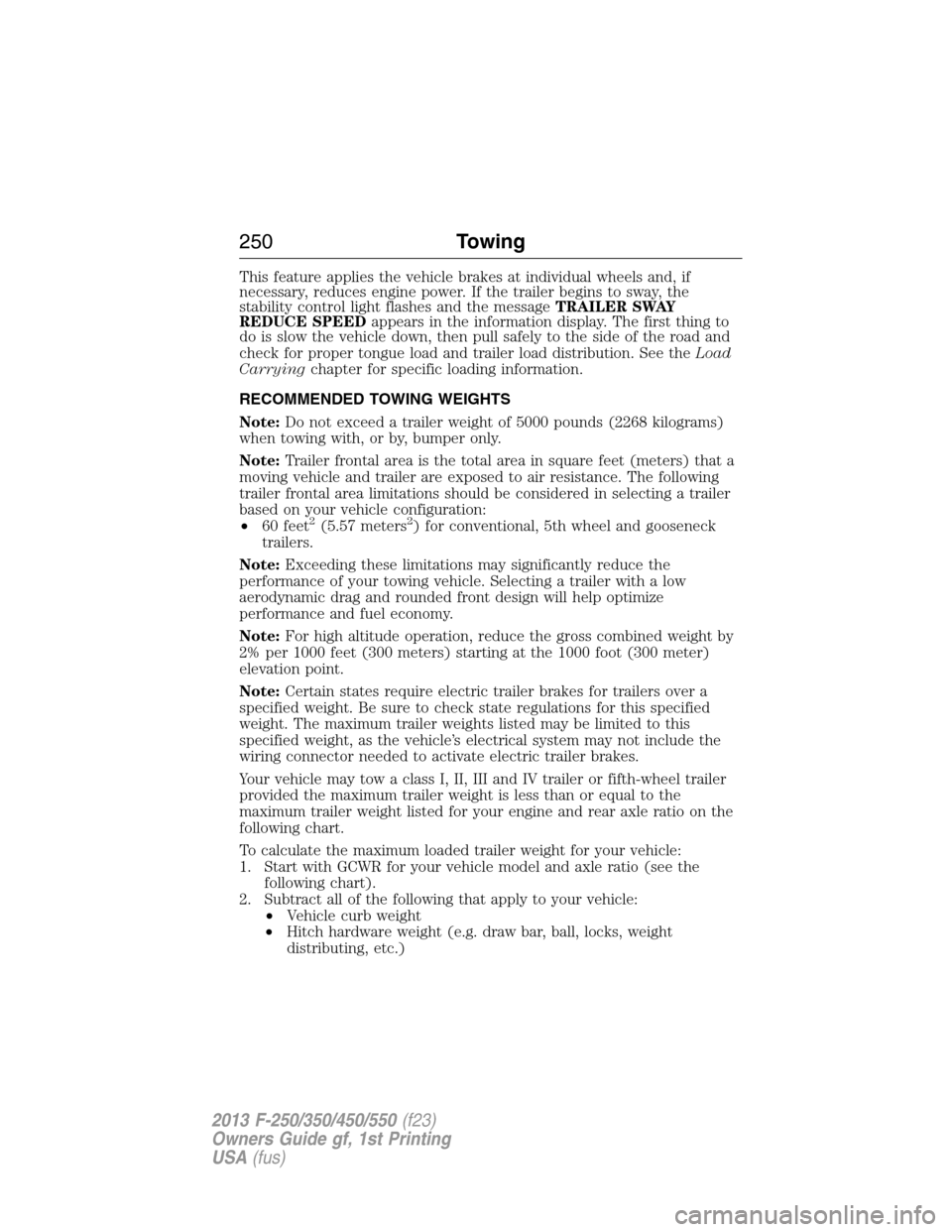
This feature applies the vehicle brakes at individual wheels and, if
necessary, reduces engine power. If the trailer begins to sway, the
stability control light flashes and the messageTRAILER SWAY
REDUCE SPEEDappears in the information display. The first thing to
do is slow the vehicle down, then pull safely to the side of the road and
check for proper tongue load and trailer load distribution. See theLoad
Carryingchapter for specific loading information.
RECOMMENDED TOWING WEIGHTS
Note:Do not exceed a trailer weight of 5000 pounds (2268 kilograms)
when towing with, or by, bumper only.
Note:Trailer frontal area is the total area in square feet (meters) that a
moving vehicle and trailer are exposed to air resistance. The following
trailer frontal area limitations should be considered in selecting a trailer
based on your vehicle configuration:
•60 feet
2(5.57 meters2) for conventional, 5th wheel and gooseneck
trailers.
Note:Exceeding these limitations may significantly reduce the
performance of your towing vehicle. Selecting a trailer with a low
aerodynamic drag and rounded front design will help optimize
performance and fuel economy.
Note:For high altitude operation, reduce the gross combined weight by
2% per 1000 feet (300 meters) starting at the 1000 foot (300 meter)
elevation point.
Note:Certain states require electric trailer brakes for trailers over a
specified weight. Be sure to check state regulations for this specified
weight. The maximum trailer weights listed may be limited to this
specified weight, as the vehicle’s electrical system may not include the
wiring connector needed to activate electric trailer brakes.
Your vehicle may tow a class I, II, III and IV trailer or fifth-wheel trailer
provided the maximum trailer weight is less than or equal to the
maximum trailer weight listed for your engine and rear axle ratio on the
following chart.
To calculate the maximum loaded trailer weight for your vehicle:
1. Start with GCWR for your vehicle model and axle ratio (see the
following chart).
2. Subtract all of the following that apply to your vehicle:
•Vehicle curb weight
•Hitch hardware weight (e.g. draw bar, ball, locks, weight
distributing, etc.)
250Towing
2013 F-250/350/450/550(f23)
Owners Guide gf, 1st Printing
USA(fus)
Page 254 of 563
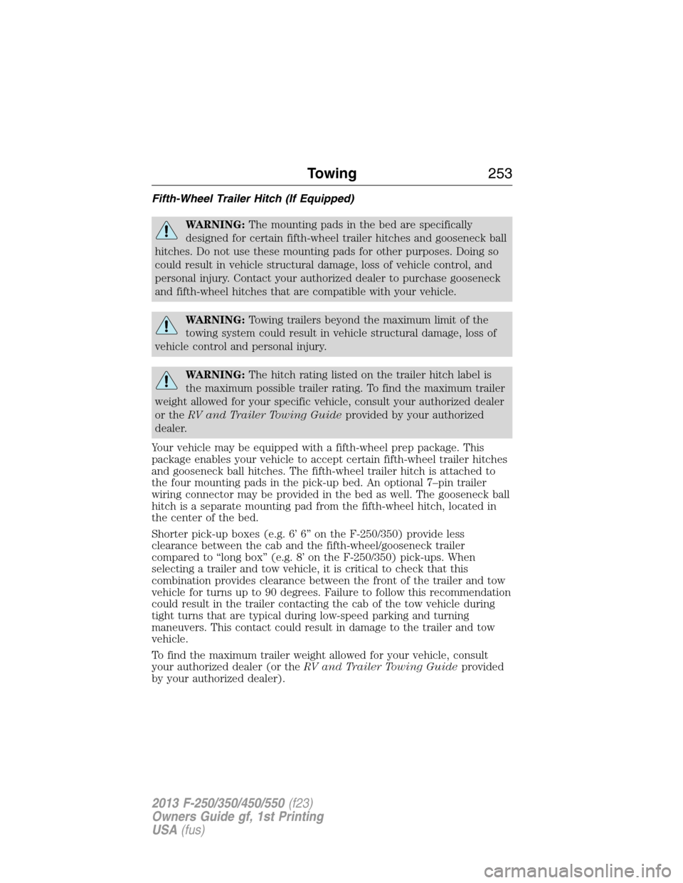
Fifth-Wheel Trailer Hitch (If Equipped)
WARNING:The mounting pads in the bed are specifically
designed for certain fifth-wheel trailer hitches and gooseneck ball
hitches. Do not use these mounting pads for other purposes. Doing so
could result in vehicle structural damage, loss of vehicle control, and
personal injury. Contact your authorized dealer to purchase gooseneck
and fifth-wheel hitches that are compatible with your vehicle.
WARNING:Towing trailers beyond the maximum limit of the
towing system could result in vehicle structural damage, loss of
vehicle control and personal injury.
WARNING:The hitch rating listed on the trailer hitch label is
the maximum possible trailer rating. To find the maximum trailer
weight allowed for your specific vehicle, consult your authorized dealer
or theRV and Trailer Towing Guideprovided by your authorized
dealer.
Your vehicle may be equipped with a fifth-wheel prep package. This
package enables your vehicle to accept certain fifth-wheel trailer hitches
and gooseneck ball hitches. The fifth-wheel trailer hitch is attached to
the four mounting pads in the pick-up bed. An optional 7–pin trailer
wiring connector may be provided in the bed as well. The gooseneck ball
hitch is a separate mounting pad from the fifth-wheel hitch, located in
the center of the bed.
Shorter pick-up boxes (e.g. 6’ 6” on the F-250/350) provide less
clearance between the cab and the fifth-wheel/gooseneck trailer
compared to “long box” (e.g. 8’ on the F-250/350) pick-ups. When
selecting a trailer and tow vehicle, it is critical to check that this
combination provides clearance between the front of the trailer and tow
vehicle for turns up to 90 degrees. Failure to follow this recommendation
could result in the trailer contacting the cab of the tow vehicle during
tight turns that are typical during low-speed parking and turning
maneuvers. This contact could result in damage to the trailer and tow
vehicle.
To find the maximum trailer weight allowed for your vehicle, consult
your authorized dealer (or theRV and Trailer Towing Guideprovided
by your authorized dealer).
Towing253
2013 F-250/350/450/550(f23)
Owners Guide gf, 1st Printing
USA(fus)
Page 256 of 563
The Ford TBC has been tested to be compatible with several major
brands of electric-over-hydraulic trailer brakes; contact your authorized
dealer for information on which brands can be used.
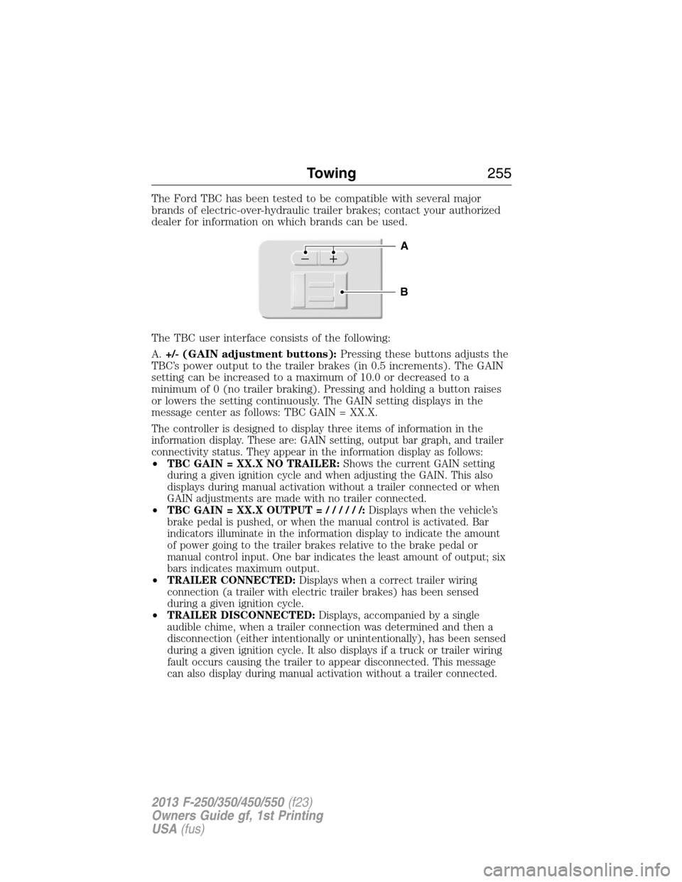
The TBC user interface consists of the following:
A.+/- (GAIN adjustment buttons):Pressing these buttons adjusts the
TBC’s power output to the trailer brakes (in 0.5 increments). The GAIN
setting can be increased to a maximum of 10.0 or decreased to a
minimum of 0 (no trailer braking). Pressing and holding a button raises
or lowers the setting continuously. The GAIN setting displays in the
message center as follows: TBC GAIN = XX.X.
The controller is designed to display three items of information in the
information display. These are: GAIN setting, output bar graph, and trailer
connectivity status. They appear in the information display as follows:
•TBC GAIN = XX.X NO TRAILER:Shows the current GAIN setting
during a given ignition cycle and when adjusting the GAIN. This also
displays during manual activation without a trailer connected or when
GAIN adjustments are made with no trailer connected.
•TBC GAIN = XX.X OUTPUT=//////:Displays when the vehicle’s
brake pedal is pushed, or when the manual control is activated. Bar
indicators illuminate in the information display to indicate the amount
of power going to the trailer brakes relative to the brake pedal or
manual control input. One bar indicates the least amount of output; six
bars indicates maximum output.
•TRAILER CONNECTED:Displays when a correct trailer wiring
connection (a trailer with electric trailer brakes) has been sensed
during a given ignition cycle.
•TRAILER DISCONNECTED:Displays, accompanied by a single
audible chime, when a trailer connection was determined and then a
disconnection (either intentionally or unintentionally), has been sensed
during a given ignition cycle. It also displays if a truck or trailer wiring
fault occurs causing the trailer to appear disconnected. This message
can also display during manual activation without a trailer connected.
B
A
Towing255
2013 F-250/350/450/550(f23)
Owners Guide gf, 1st Printing
USA(fus)
Page 258 of 563
Explanation of Information Display Warning Messages
Note:Your TBC can be diagnosed by your authorized dealer to determine
exactly which trailer fault has occurred. However, if the fault is with the
trailer this diagnosis isnotcovered under your Ford warranty.
TRAILER BRAKE MODULE FAULT:Displays in response to faults
sensed by the TBC (accompanied by a single chime). If this message is
displayed, please contact your authorized dealer as soon as possible for
diagnosis and repair. The TBC may still function, but performance may
be degraded.
WIRING FAULT ON TRAILER:Displays when a short circuit on the
electric brake output wire has occurred. If theWIRING FAULT ON
TRAILERmessage is displayed and accompanied by a single chime,
with no trailer connected, the problem is with the vehicle wiring between
the TBC to the 7–pin connector at the bumper. If the message is only
displayed with a trailer connected, the problem is related to the trailer
wiring. Consult your trailer dealer for assistance. This can be a short to
ground (i.e., chaffed wire), short to voltage (i.e., pulled pin on trailer
emergency break-away battery) or the trailer brakes may be drawing too
much current.
Points to Remember
Note:Do not attempt removal of the TBC without consulting the
Workshop Manual.Damage to the unit may result.
•Adjust GAIN setting before using the TBC for the first time.
•Adjust GAIN setting (according to procedure above) whenever road,
weather and trailer or vehicle loading conditions change from when
the GAIN was initially set.
•The manual control lever should only be used for proper adjustment
of the GAIN during trailer setup. Misuse, such as application during
trailer sway, could cause instability of trailer or tow vehicle.
•Avoid towing in adverse weather conditions. The TBC does not
provide anti-lock control of the trailer wheels. Trailer wheels can lock
up on slippery surfaces, resulting in reduced stability of trailer and
tow vehicle.
•The TBC is equipped with a feature which reduces output at vehicle
speeds below 11 mph (18 km/h) so trailer and vehicle braking is not
jerky or harsh. This feature is only available when applying the brakes
using the vehicle’s brake pedal, not the TBC.
•The controller interacts with the brake control system and powertrain
control system of the vehicle to provide the best performance on
different road conditions.
Towing257
2013 F-250/350/450/550(f23)
Owners Guide gf, 1st Printing
USA(fus)
Page 260 of 563

•Shift to a lower gear when driving down a long or steep hill. Do not
apply the brakes continuously, as they may overheat and become less
effective.
•If your transmission is equipped with the tow/haul feature, use this
when towing. This provides engine braking and helps eliminate
excessive transmission shifting for optimum fuel economy and
transmission cooling.
•If your vehicle is equipped with AdvanceTrac™ with RSC, you may
experience AdvanceTrac™ with RSC activations during typical
cornering maneuvers with a heavily loaded trailer; this is normal.
Cornering at a slower speed while towing reduces the tendency of the
AdvanceTrac™ stability enhancement system to activate.
•If you are towing a trailer frequently in hot weather, hilly conditions,
at GCWR (or any combination of these factors), consider refilling your
rear axle with synthetic gear lubricant, if not already so equipped. See
theCapacities and Specificationschapter for the lubricant
specification.
•Allow more distance for stopping with a trailer attached; anticipate
stops and brake gradually.
•Avoid parking on a grade. However, if you must park on a grade, place
wheel chocks under the trailer’s wheels.
Your vehicle may be equipped with a temporary or conventional spare
tire. If the spare tire is different in size (diameter and/or width), tread
type (All-Season or All-Terrain) or is from a different manufacturer other
than the road tires on your vehicle, your spare tire is considered
“temporary”. Consult information on the Tire Label or Safety Compliance
Certification Label for limitations when using.
Launching or Retrieving a Boat or Personal Watercraft (PWC)
Note:Disconnect the wiring to the trailerbeforebacking the trailer into
the water.
Note:Reconnect the wiring to the trailer after the trailer is removed
from the water.
When backing down a ramp during boat launching or retrieval:
•Do not allow the static water level to rise above the bottom edge of
the rear bumper.
•Do not allow waves to break higher than 6 inches (15 centimeters)
above the bottom edge of the rear bumper.
Towing259
2013 F-250/350/450/550(f23)
Owners Guide gf, 1st Printing
USA(fus)
Page 271 of 563

Transmission operation while plowing
WARNING:Do not spin the wheels at over 35 mph (55 km/h).
The tires may fail and injure a passenger or bystander.
•Shift transfer case to4L(4WD Low) when plowing in small areas at
speeds below 5 mph (8 km/h).
•Shift transfer case to4H(4WD High) when plowing larger areas or
light snow at higher speeds. Do not exceed 15 mph (24 km/h).
•Do not shift the transmission from a forward gear toR(Reverse) until
the engine is at idle and the wheels are stopped.
•If the vehicle is stuck, shift the transmission in a steady motion
between forward and reverse gears. Do not rock the vehicle for more
than a minute. The transmission and tires may be damaged or the
engine can overheat.
Outside Air Temperature While Plowing
The outside air temperature reading can be inaccurate while plowing
with your vehicle due to the sensor air flow being blocked by the plow
blade.
A Ford Wiring Kit (XXXX-XXXXX-XX) is available to relocated the OAT
sensor to the plow blade frame below the headlamp to provide accurate
outside air temperature readings.
VEHICLE USED AS A STATIONARY POWER SOURCE
Auxiliary equipment called power take-off, or PTO, is often added to the
engine or transmission to operate utility equipment. Examples include a
wheel-lift for tow trucks, cranes, tools for construction or tire service,
and pumping fluids. PTO applications draw auxiliary horsepower from
the powertrain, often while the vehicle is stationary. In this condition,
there is limited cooling air flow through the radiator and around the
vehicle that normally occurs when a vehicle is moving. The aftermarket
PTO system installer, having the most knowledge of the final application,
is responsible for determining whether additional chassis heat protection
or powertrain cooling is required, and alerting the user to the safe and
proper operation.
Ford Super Duty Vehicles are approved for use as a stationary (including
split shaft capability) or mobile power source, within limits and operating
guidelines detailed in theFord Truck Body Builders Layout Book,
found at www.fleet.ford.com/truckbbas, and through the Ford Truck
Body Builders Advisory Service.
270Driving Hints
2013 F-250/350/450/550(f23)
Owners Guide gf, 1st Printing
USA(fus)
Page 325 of 563
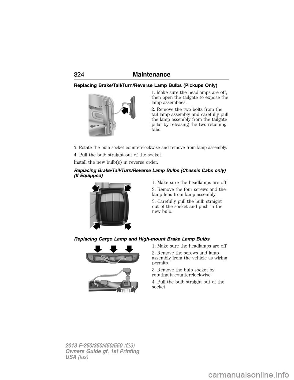
Replacing Brake/Tail/Turn/Reverse Lamp Bulbs (Pickups Only)
1. Make sure the headlamps are off,
then open the tailgate to expose the
lamp assemblies.
2. Remove the two bolts from the
tail lamp assembly and carefully pull
the lamp assembly from the tailgate
pillar by releasing the two retaining
tabs.
3. Rotate the bulb socket counterclockwise and remove from lamp assembly.
4. Pull the bulb straight out of the socket.
Install the new bulb(s) in reverse order.
Replacing Brake/Tail/Turn/Reverse Lamp Bulbs (Chassis Cabs only)
(If Equipped)
1. Make sure the headlamps are off.
2. Remove the four screws and the
lamp lens from lamp assembly.
3. Carefully pull the bulb straight
out of the socket and push in the
new bulb.
Replacing Cargo Lamp and High-mount Brake Lamp Bulbs
1. Make sure the headlamps are off.
2. Remove the screws and lamp
assembly from the vehicle as wiring
permits.
3. Remove the bulb socket by
rotating it counterclockwise.
4. Pull the bulb straight out of the
socket.
324Maintenance
2013 F-250/350/450/550(f23)
Owners Guide gf, 1st Printing
USA(fus)