2013 FORD SUPER DUTY wheel torque
[x] Cancel search: wheel torquePage 8 of 563
Wheels and Tires 338
Tire care...........................................341
Tire Pressure Monitoring System (TPMS)...................360
Changing a road wheel.................................366
Technical specifications.................................380
Wheel lug nut torque..................................380
Capacities and Specifications 382
Engine specifications..................................382
Engine drivebelt......................................382
Part numbers........................................388
Vehicle identification number............................389
Vehicle certification label...............................390
Transmission code designation............................390
Accessories 391
Accessories.........................................391
Ford Extended Service Plan 393
Scheduled Maintenance 396
Normal scheduled maintenance and log.....................401
SYNC® 413
Pairing your phone for the first time.......................418
911 Assist™.........................................432
Vehicle Health Report..................................435
Table of Contents7
2013 F-250/350/450/550(f23)
Owners Guide gf, 1st Printing
USA(fus)
Page 133 of 563
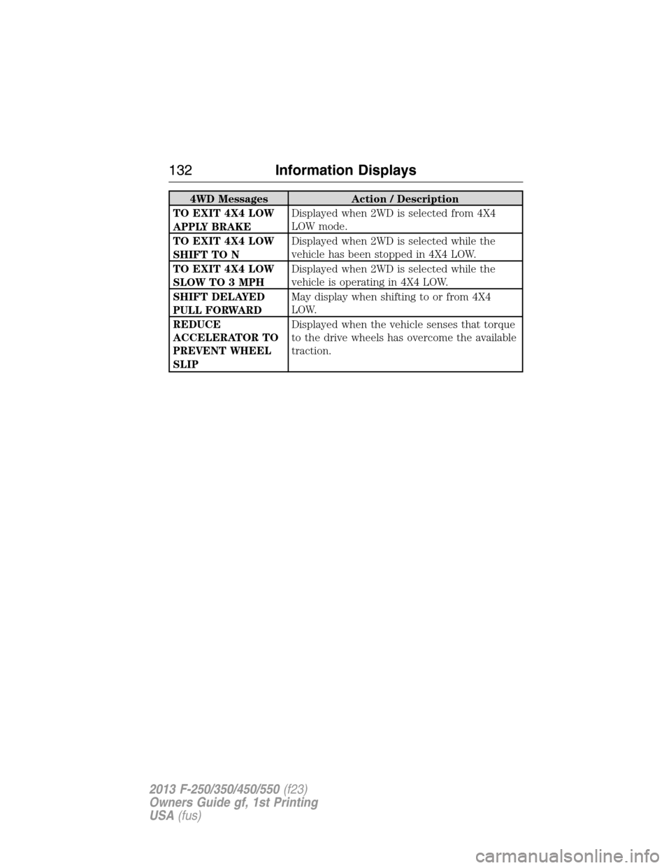
4WD Messages Action / Description
TO EXIT 4X4 LOW
APPLY BRAKEDisplayed when 2WD is selected from 4X4
LOW mode.
TO EXIT 4X4 LOW
SHIFT TO NDisplayed when 2WD is selected while the
vehicle has been stopped in 4X4 LOW.
TO EXIT 4X4 LOW
SLOW TO 3 MPHDisplayed when 2WD is selected while the
vehicle is operating in 4X4 LOW.
SHIFT DELAYED
PULL FORWARDMay display when shifting to or from 4X4
LOW.
REDUCE
ACCELERATOR TO
PREVENT WHEEL
SLIPDisplayed when the vehicle senses that torque
to the drive wheels has overcome the available
traction.
132Information Displays
2013 F-250/350/450/550(f23)
Owners Guide gf, 1st Printing
USA(fus)
Page 214 of 563
Activating the Electronic Locking Differential (ELD)
Note:The ELD may have difficulty disengaging either by operator
command or automatically if the driveline is under torque. If driving
conditions allow, releasing the accelerator pedal or turning the steering
wheel in the opposite direction may assist in disengagement.
Note:The ELD is designed for off-road use only and is not intended for
use on dry pavement.
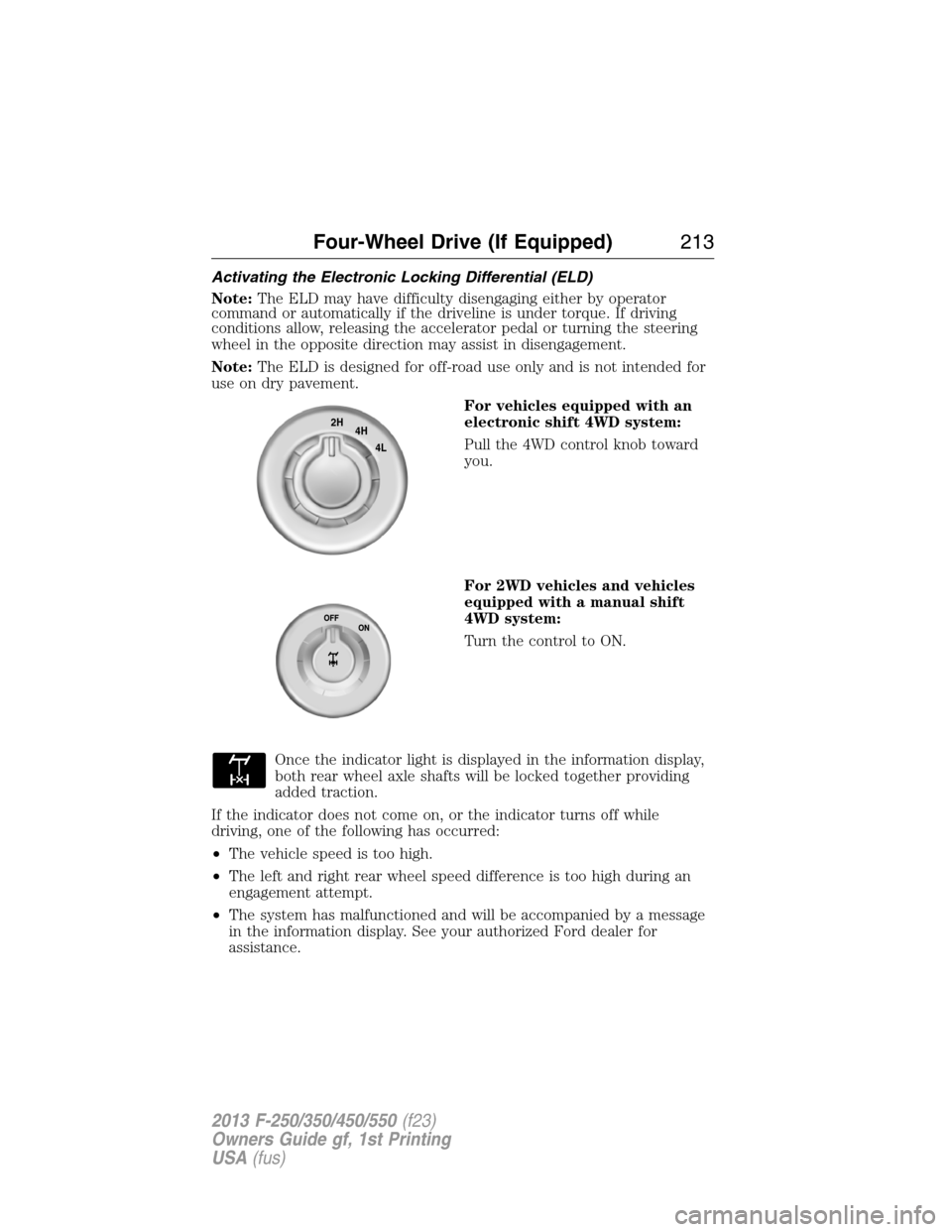
For vehicles equipped with an
electronic shift 4WD system:
Pull the 4WD control knob toward
you.
For 2WD vehicles and vehicles
equipped with a manual shift
4WD system:
Turn the control to ON.
Once the indicator light is displayed in the information display,
both rear wheel axle shafts will be locked together providing
added traction.
If the indicator does not come on, or the indicator turns off while
driving, one of the following has occurred:
•The vehicle speed is too high.
•The left and right rear wheel speed difference is too high during an
engagement attempt.
•The system has malfunctioned and will be accompanied by a message
in the information display. See your authorized Ford dealer for
assistance.
2H
4H
4L
Four-Wheel Drive (If Equipped)213
2013 F-250/350/450/550(f23)
Owners Guide gf, 1st Printing
USA(fus)
Page 237 of 563
Steering
To help prevent damage to the power steering system:
•Never hold the steering wheel at its furthest turning points (until it
stops) for more than three to five seconds when the engine is running.
•Do not operate the vehicle with a low power steering pump fluid level
(below the MIN mark on the reservoir).
•Some noise is normal during operation. If excessive, check for low
power steering pump fluid level before seeking service by your dealer.
•Heavy or uneven efforts may be caused by low power steering fluid.
Check for low power steering pump fluid level before seeking service
by your dealer.
•Do not fill the power steering pump reservoir above the MAX mark on
the reservoir, as this may result in leaks from the reservoir.
If the power steering system breaks down (or if the engine is turned
off), you can steer the vehicle manually, but it takes more effort.
If the steering wanders or pulls, check for:
•an improperly inflated tire
•uneven tire wear
•loose or worn suspension components
•loose or worn steering components
•improper steering alignment
If any steering components are serviced or replaced, install new
fasteners (many are coated with thread adhesive or have prevailing
torque features which may not be re-used). Never re-use a bolt or nut.
Torque fasteners to specifications inWorkshop Manual.
A high crown in the road or high crosswinds may also make the steering
seem to wander/pull.
236Driving Aids
2013 F-250/350/450/550(f23)
Owners Guide gf, 1st Printing
USA(fus)
Page 378 of 563
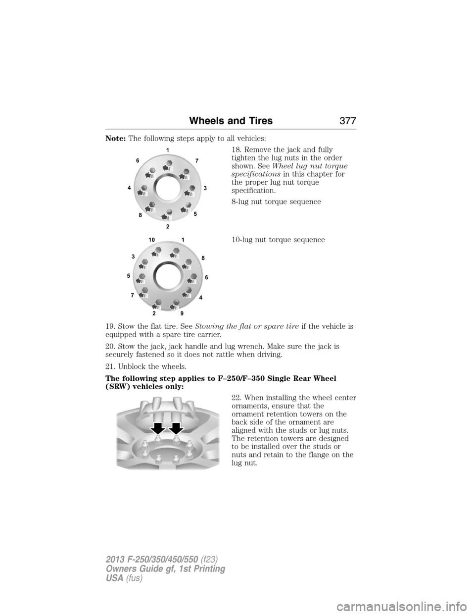
Note:The following steps apply to all vehicles:
18. Remove the jack and fully
tighten the lug nuts in the order
shown. SeeWheel lug nut torque
specificationsin this chapter for
the proper lug nut torque
specification.
8-lug nut torque sequence
10-lug nut torque sequence
19. Stow the flat tire. SeeStowing the flat or spare tireif the vehicle is
equipped with a spare tire carrier.
20. Stow the jack, jack handle and lug wrench. Make sure the jack is
securely fastened so it does not rattle when driving.
21. Unblock the wheels.
The following step applies to F–250/F–350 Single Rear Wheel
(SRW) vehicles only:
22. When installing the wheel center
ornaments, ensure that the
ornament retention towers on the
back side of the ornament are
aligned with the studs or lug nuts.
The retention towers are designed
to be installed over the studs or
nuts and retain to the flange on the
lug nut.
1
3 4
27 6
5
8
1
2 3
4 5
6
78
9 10
Wheels and Tires377
2013 F-250/350/450/550(f23)
Owners Guide gf, 1st Printing
USA(fus)
Page 381 of 563
3. Lay the tire on the ground with the valve stem facing up.
4. Slide the wheel partially under the vehicle and install the retainer
through the wheel center. Pull on the cable to align the components at
the end of the cable.
5. Turn the jack handle clockwise until the tire is raised to its stowed
position underneath the vehicle. The effort to turn the jack handle
increases significantly and the spare tire carrier ratchets or slips when
the tire is raised to the maximum tightness. Tighten to the best of your
ability, to the point where the ratchet/slip occurs, if possible. The spare
tire carrier will not allow you to overtighten. If the spare tire carrier
ratchets or slips with little effort, take the vehicle to your authorized
dealer for assistance at your earliest convenience.
6. Check that the tire lies flat against the frame and is properly
tightened. Try to push or pull, then turn the tire to be sure it will not
move. Loosen and retighten, if necessary. Failure to properly stow the
spare tire may result in failure of the winch cable and loss of the tire.
7. Repeat this tightness check procedure when servicing the spare tire
pressure (every six months, perscheduled maintenance information),
or at any time that the spare tire is disturbed through service of other
components.
8. If removed, install the spare tire lock (if equipped) into the bumper
drive tube with the spare tire lock key (if equipped) and jack handle.
TECHNICAL SPECIFICATIONS
Wheel Lug Nut Torque Specifications
WARNING:When a wheel is installed, always remove any
corrosion, dirt or foreign materials present on the mounting
surfaces of the wheel or the surface of the wheel hub, brake drum or
brake disc that contacts the wheel. Make sure that any fasteners that
attach the rotor to the hub are secured so they do not interfere with
the mounting surfaces of the wheel. Installing wheels without correct
metal-to-metal contact at the wheel mounting surfaces can cause the
wheel nuts to loosen and the wheel to come off while the vehicle is in
motion, resulting in loss of control.
On vehicles equipped with single rear wheels, retighten the lug nuts to
the specified torque at 100 miles (160 kilometers) after any wheel
disturbance (such as tire rotation, changing a flat tire, wheel removal).
380Wheels and Tires
2013 F-250/350/450/550(f23)
Owners Guide gf, 1st Printing
USA(fus)
Page 382 of 563
On vehicles equipped with dual rear wheels, retighten the wheel lug nuts
to the specified torque at 100 miles (160 kilometers), and again at
500 miles (800 kilometers) of new vehicle operation and after any wheel
disturbance (such as tire rotation, changing a flat tire, wheel removal).
Bolt size Wheel lug nut torque*
ft-lb N•m
M14 x 1.5 165 224
* Torque specifications are for nut and bolt threads free of dirt and
rust. Use only Ford recommended replacement fasteners.
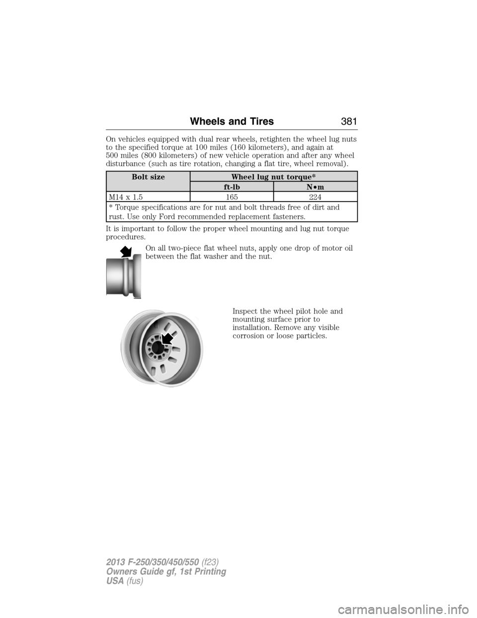
It is important to follow the proper wheel mounting and lug nut torque
procedures.
On all two-piece flat wheel nuts, apply one drop of motor oil
between the flat washer and the nut.
Inspect the wheel pilot hole and
mounting surface prior to
installation. Remove any visible
corrosion or loose particles.
Wheels and Tires381
2013 F-250/350/450/550(f23)
Owners Guide gf, 1st Printing
USA(fus)