2013 FORD SUPER DUTY headlamp
[x] Cancel search: headlampPage 102 of 563
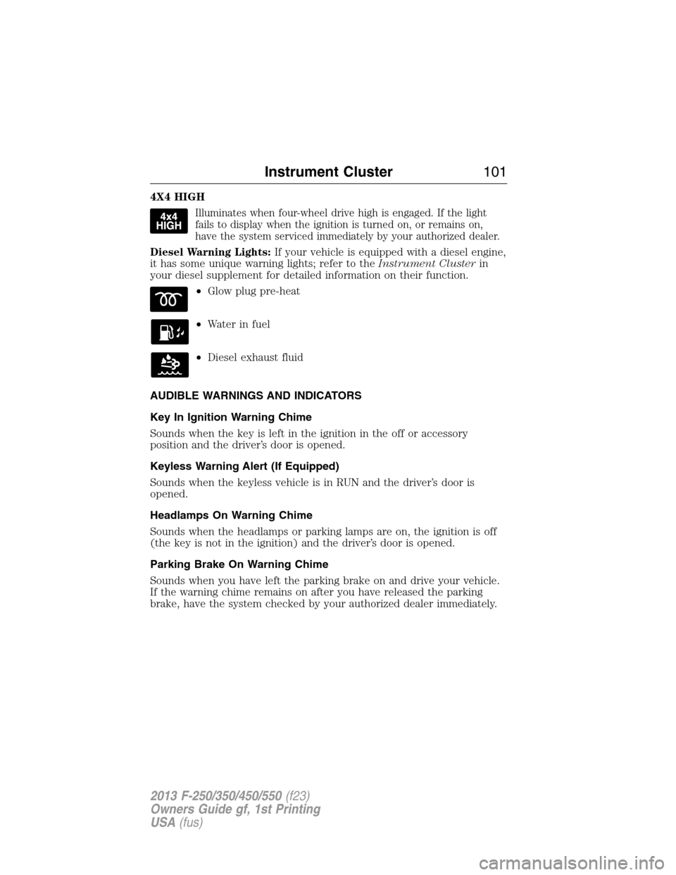
4X4 HIGH
Illuminates when four-wheel drive high is engaged. If the light
fails to display when the ignition is turned on, or remains on,
have the system serviced immediately by your authorized dealer.
Diesel Warning Lights:If your vehicle is equipped with a diesel engine,
it has some unique warning lights; refer to theInstrument Clusterin
your diesel supplement for detailed information on their function.
•Glow plug pre-heat
•Waterinfuel
•Diesel exhaust fluid
AUDIBLE WARNINGS AND INDICATORS
Key In Ignition Warning Chime
Sounds when the key is left in the ignition in the off or accessory
position and the driver’s door is opened.
Keyless Warning Alert (If Equipped)
Sounds when the keyless vehicle is in RUN and the driver’s door is
opened.
Headlamps On Warning Chime
Sounds when the headlamps or parking lamps are on, the ignition is off
(the key is not in the ignition) and the driver’s door is opened.
Parking Brake On Warning Chime
Sounds when you have left the parking brake on and drive your vehicle.
If the warning chime remains on after you have released the parking
brake, have the system checked by your authorized dealer immediately.
Instrument Cluster101
2013 F-250/350/450/550(f23)
Owners Guide gf, 1st Printing
USA(fus)
Page 184 of 563
IGNITION SWITCH
Note:To switch the engine off when your vehicle is moving, move the
transmission selector lever to positionN.Use the brakes to bring your
vehicle to a safe stop. After your vehicle has stopped, switch the engine
off and move the transmission selector lever to positionP.Turn the key
to the accessory or off position.
Note:Do not store the key in the ignition after the vehicle is turned off
and you have left the vehicle. This could cause a drain on the battery.
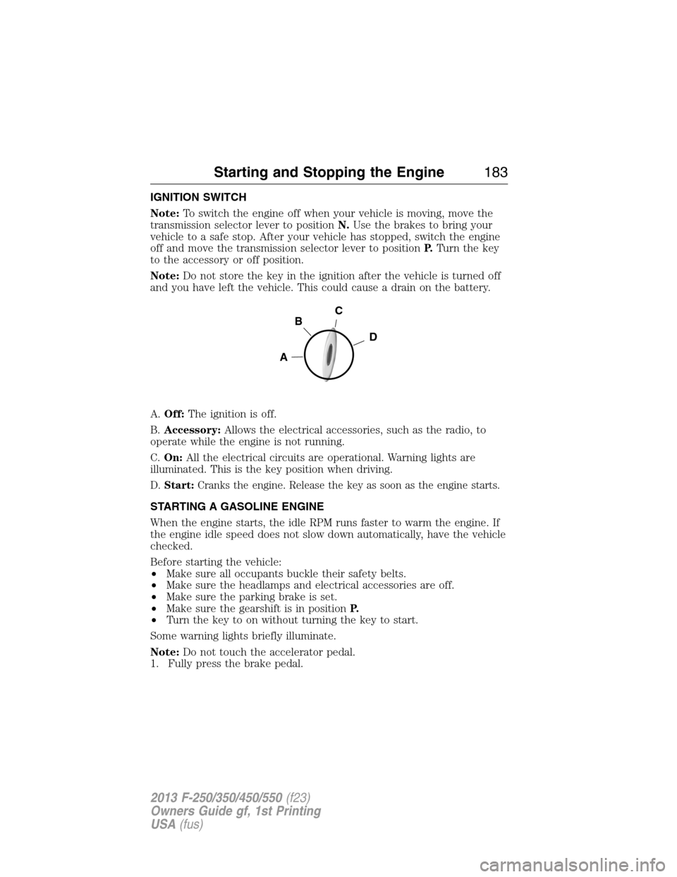
A.Off:The ignition is off.
B.Accessory:Allows the electrical accessories, such as the radio, to
operate while the engine is not running.
C.On:All the electrical circuits are operational. Warning lights are
illuminated. This is the key position when driving.
D.Start:Cranks the engine. Release the key as soon as the engine starts.
STARTING A GASOLINE ENGINE
When the engine starts, the idle RPM runs faster to warm the engine. If
the engine idle speed does not slow down automatically, have the vehicle
checked.
Before starting the vehicle:
•Make sure all occupants buckle their safety belts.
•Make sure the headlamps and electrical accessories are off.
•Make sure the parking brake is set.
•Make sure the gearshift is in positionP.
•Turn the key to on without turning the key to start.
Some warning lights briefly illuminate.
Note:Do not touch the accelerator pedal.
1. Fully press the brake pedal.
C
D
B
A
Starting and Stopping the Engine183
2013 F-250/350/450/550(f23)
Owners Guide gf, 1st Printing
USA(fus)
Page 271 of 563

Transmission operation while plowing
WARNING:Do not spin the wheels at over 35 mph (55 km/h).
The tires may fail and injure a passenger or bystander.
•Shift transfer case to4L(4WD Low) when plowing in small areas at
speeds below 5 mph (8 km/h).
•Shift transfer case to4H(4WD High) when plowing larger areas or
light snow at higher speeds. Do not exceed 15 mph (24 km/h).
•Do not shift the transmission from a forward gear toR(Reverse) until
the engine is at idle and the wheels are stopped.
•If the vehicle is stuck, shift the transmission in a steady motion
between forward and reverse gears. Do not rock the vehicle for more
than a minute. The transmission and tires may be damaged or the
engine can overheat.
Outside Air Temperature While Plowing
The outside air temperature reading can be inaccurate while plowing
with your vehicle due to the sensor air flow being blocked by the plow
blade.
A Ford Wiring Kit (XXXX-XXXXX-XX) is available to relocated the OAT
sensor to the plow blade frame below the headlamp to provide accurate
outside air temperature readings.
VEHICLE USED AS A STATIONARY POWER SOURCE
Auxiliary equipment called power take-off, or PTO, is often added to the
engine or transmission to operate utility equipment. Examples include a
wheel-lift for tow trucks, cranes, tools for construction or tire service,
and pumping fluids. PTO applications draw auxiliary horsepower from
the powertrain, often while the vehicle is stationary. In this condition,
there is limited cooling air flow through the radiator and around the
vehicle that normally occurs when a vehicle is moving. The aftermarket
PTO system installer, having the most knowledge of the final application,
is responsible for determining whether additional chassis heat protection
or powertrain cooling is required, and alerting the user to the safe and
proper operation.
Ford Super Duty Vehicles are approved for use as a stationary (including
split shaft capability) or mobile power source, within limits and operating
guidelines detailed in theFord Truck Body Builders Layout Book,
found at www.fleet.ford.com/truckbbas, and through the Ford Truck
Body Builders Advisory Service.
270Driving Hints
2013 F-250/350/450/550(f23)
Owners Guide gf, 1st Printing
USA(fus)
Page 293 of 563
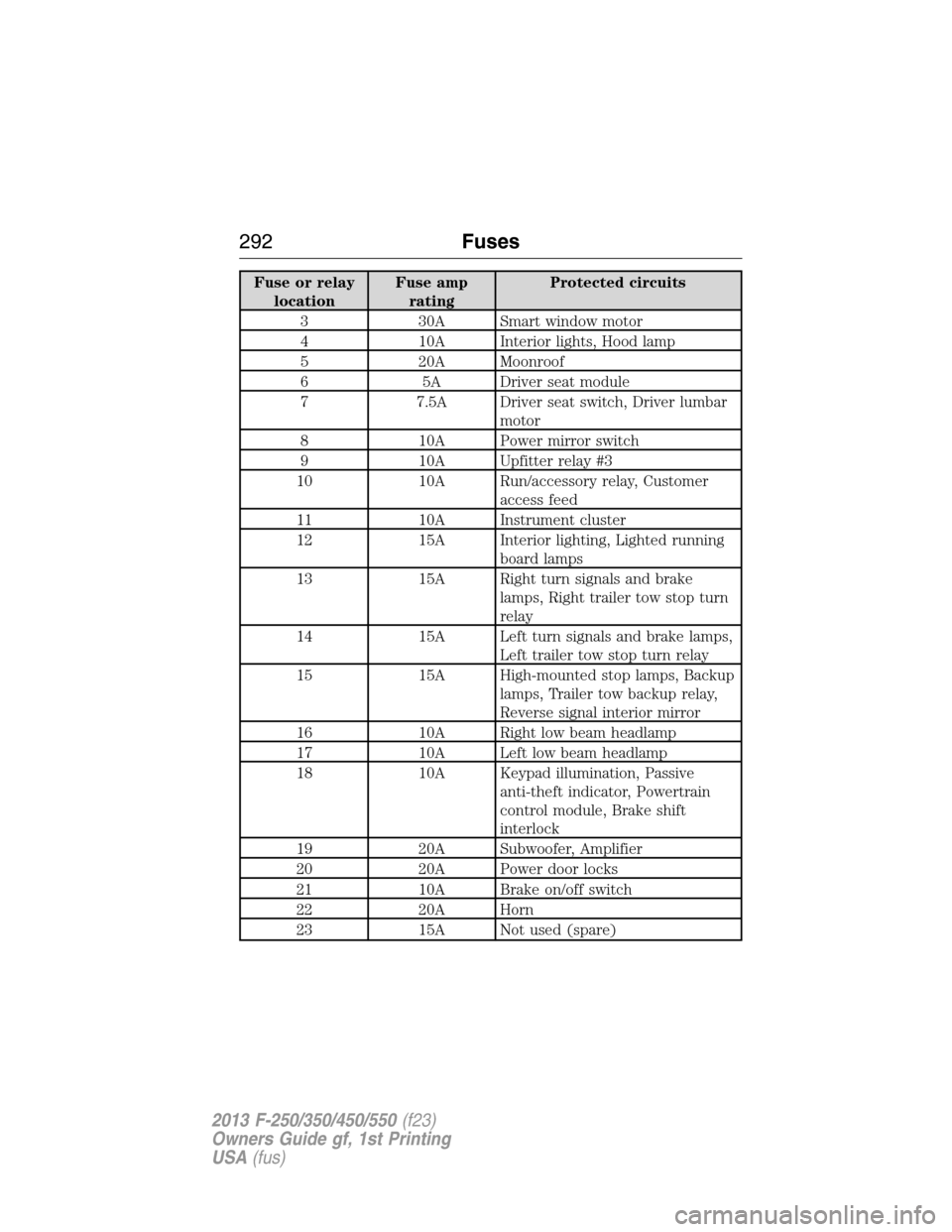
Fuse or relay
locationFuse amp
ratingProtected circuits
3 30A Smart window motor
4 10A Interior lights, Hood lamp
5 20A Moonroof
6 5A Driver seat module
7 7.5A Driver seat switch, Driver lumbar
motor
8 10A Power mirror switch
9 10A Upfitter relay #3
10 10A Run/accessory relay, Customer
access feed
11 10A Instrument cluster
12 15A Interior lighting, Lighted running
board lamps
13 15A Right turn signals and brake
lamps, Right trailer tow stop turn
relay
14 15A Left turn signals and brake lamps,
Left trailer tow stop turn relay
15 15A High-mounted stop lamps, Backup
lamps, Trailer tow backup relay,
Reverse signal interior mirror
16 10A Right low beam headlamp
17 10A Left low beam headlamp
18 10A Keypad illumination, Passive
anti-theft indicator, Powertrain
control module, Brake shift
interlock
19 20A Subwoofer, Amplifier
20 20A Power door locks
21 10A Brake on/off switch
22 20A Horn
23 15A Not used (spare)
292Fuses
2013 F-250/350/450/550(f23)
Owners Guide gf, 1st Printing
USA(fus)
Page 294 of 563

Fuse or relay
locationFuse amp
ratingProtected circuits
24 15A Steering wheel control module,
Diagnostic connector, Power fold
mirror relay, Remote keyless
entry, Electronic finish panel
25 15A Not used (spare)
26 5A Steering wheel control module
27 20A Not used (spare)
28 15A Ignition switch
29 20A SYNC, GPS module, Radio
faceplate
30 15A Parking lamp relay, Trailer tow
parking lamp relay
31 5A Trailer brake controller (brake
signal), Customer access
32 15A Moonroof motor, Telescoping
mirror switch, Auto dimming
mirrors, Power inverter, Driver
and passenger door lock switch
illumination, Rear heated seat
switch illumination
33 10A Restraint control module
34 10A Heated steering wheel module,
Rear heated seats module
35 5A Select shift switch, Reverse park
aid module, Trailer brake control
module
36 10A Fuel tank select switch
37 10A PTC heater
38 10A AM/FM radio faceplate
39 15A High beam headlamps
40 10A Parking lamps (in mirrors), Roof
marker lamps
Fuses293
2013 F-250/350/450/550(f23)
Owners Guide gf, 1st Printing
USA(fus)
Page 320 of 563

10. Reconnect the mass air flow
sensor electrical connector to the
outlet tube. Make sure the locking
tab on the connector is in the
“locked” position (connector shown
from below for clarity).
ADJUSTING THE HEADLAMPS
The headlamps on your vehicle are properly aimed at the assembly plant.
If your vehicle has been in an accident, the alignment of your headlamps
should be checked by your authorized dealer.
Vertical Aim Adjustment
1. Park the vehicle directly in front of a wall or screen on a level surface,
approximately 25 feet (7.6 meters) away.
•(A) 8 feet (2.4 meters)
•(B) Center height of lamp to
ground
•(C) 25 feet (7.6 meters)
•(D) Horizontal reference line
2. Measure the height from the
center of your headlamp (indicated
by a 3.0 millimeter circle on the
lens) to the ground and mark an
8 foot (2.4 meter) horizontal
reference line on the vertical wall or screen at this height (a piece of
masking tape works well).
3. Turn on the low beam headlamps to illuminate the wall or screen and
open the hood. Cover one of the headlamps so no light from that lamp
hits the wall.
C
A
B
D
Maintenance319
2013 F-250/350/450/550(f23)
Owners Guide gf, 1st Printing
USA(fus)
Page 321 of 563
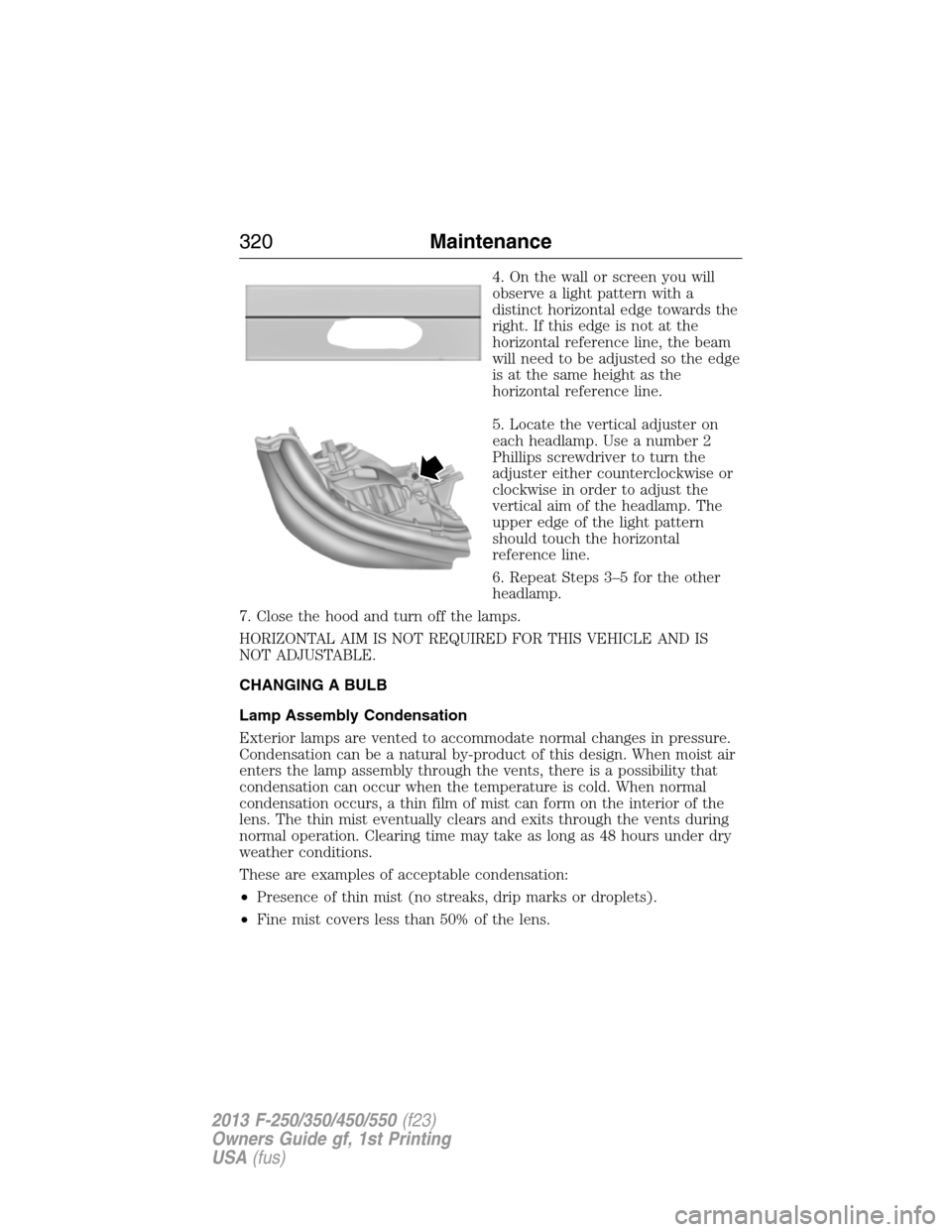
4. On the wall or screen you will
observe a light pattern with a
distinct horizontal edge towards the
right. If this edge is not at the
horizontal reference line, the beam
will need to be adjusted so the edge
is at the same height as the
horizontal reference line.
5. Locate the vertical adjuster on
each headlamp. Use a number 2
Phillips screwdriver to turn the
adjuster either counterclockwise or
clockwise in order to adjust the
vertical aim of the headlamp. The
upper edge of the light pattern
should touch the horizontal
reference line.
6. Repeat Steps 3–5 for the other
headlamp.
7. Close the hood and turn off the lamps.
HORIZONTAL AIM IS NOT REQUIRED FOR THIS VEHICLE AND IS
NOT ADJUSTABLE.
CHANGING A BULB
Lamp Assembly Condensation
Exterior lamps are vented to accommodate normal changes in pressure.
Condensation can be a natural by-product of this design. When moist air
enters the lamp assembly through the vents, there is a possibility that
condensation can occur when the temperature is cold. When normal
condensation occurs, a thin film of mist can form on the interior of the
lens. The thin mist eventually clears and exits through the vents during
normal operation. Clearing time may take as long as 48 hours under dry
weather conditions.
These are examples of acceptable condensation:
•Presence of thin mist (no streaks, drip marks or droplets).
•Fine mist covers less than 50% of the lens.
320Maintenance
2013 F-250/350/450/550(f23)
Owners Guide gf, 1st Printing
USA(fus)
Page 322 of 563
These are examples of unacceptable moisture (usually caused by a lamp
water leak):
•Water puddle inside the lamp.
•Large water droplets, drip marks or streaks present on the interior of
the lens.
Take your vehicle to a dealer for service if any of the above conditions of
unacceptable moisture are present.
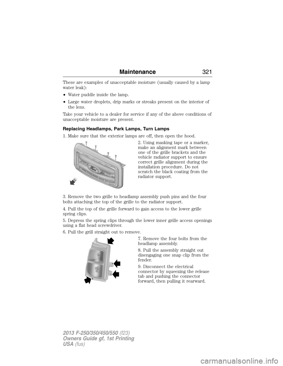
Replacing Headlamps, Park Lamps, Turn Lamps
1. Make sure that the exterior lamps are off, then open the hood.
2. Using masking tape or a marker,
make an alignment mark between
one of the grille brackets and the
vehicle radiator support to ensure
correct grille alignment during the
installation procedure. Do not
scratch the black coating from the
radiator support.
3. Remove the two grille to headlamp assembly push pins and the four
bolts attaching the top of the grille to the radiator support.
4. Pull the top of the grille forward to gain access to the lower grille
spring clips.
5. Depress the spring clips through the lower inner grille access openings
using a flat head screwdriver.
6. Pull the grill straight out to remove.
7. Remove the four bolts from the
headlamp assembly.
8. Pull the assembly straight out
disengaging one snap clip from the
fender.
9. Disconnect the electrical
connector by squeezing the release
tab and pushing the connector
forward, then pulling it rearward.
Maintenance321
2013 F-250/350/450/550(f23)
Owners Guide gf, 1st Printing
USA(fus)