Page 324 of 563
Replacing Front Clearance and Identification Lamp Bulbs
(If Equipped)
1. Make sure the headlamps are off.
2. Remove the screw and lens from
the lamp assembly.
3. Pull the bulb straight out of the
socket.
Install the bulb(s) in reverse order.
Replacing Fog Lamp Bulbs (If Equipped)
1. Make sure the headlamps are off.
2. Remove the bulb socket from the
fog lamp by turning it
counterclockwise.
3. Disconnect the electrical
connector from the fog lamp bulb.
Install the new bulb(s) in reverse order.
Maintenance323
2013 F-250/350/450/550(f23)
Owners Guide gf, 1st Printing
USA(fus)
Page 325 of 563

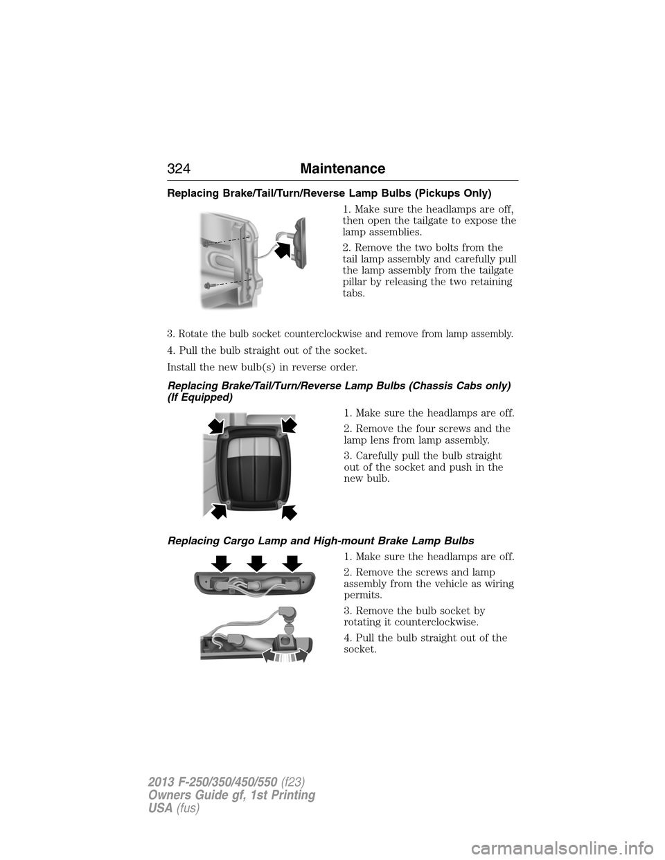
Replacing Brake/Tail/Turn/Reverse Lamp Bulbs (Pickups Only)
1. Make sure the headlamps are off,
then open the tailgate to expose the
lamp assemblies.
2. Remove the two bolts from the
tail lamp assembly and carefully pull
the lamp assembly from the tailgate
pillar by releasing the two retaining
tabs.
3. Rotate the bulb socket counterclockwise and remove from lamp assembly.
4. Pull the bulb straight out of the socket.
Install the new bulb(s) in reverse order.
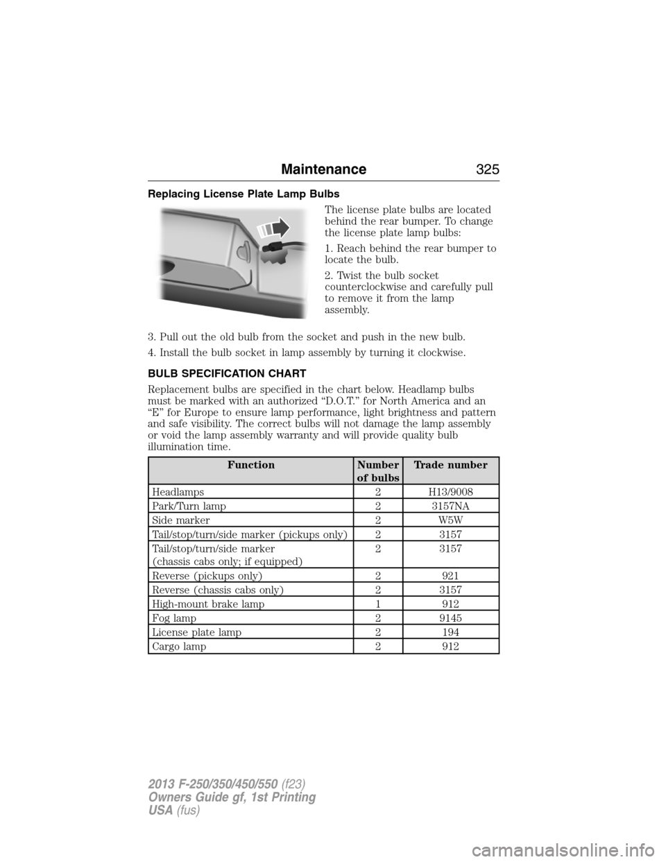
Replacing Brake/Tail/Turn/Reverse Lamp Bulbs (Chassis Cabs only)
(If Equipped)
1. Make sure the headlamps are off.
2. Remove the four screws and the
lamp lens from lamp assembly.
3. Carefully pull the bulb straight
out of the socket and push in the
new bulb.
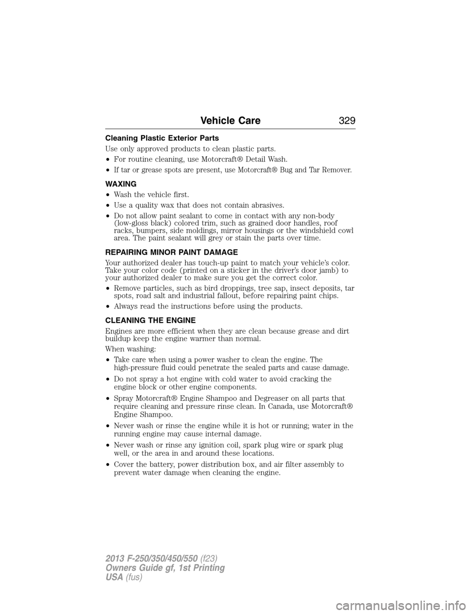
Replacing Cargo Lamp and High-mount Brake Lamp Bulbs
1. Make sure the headlamps are off.
2. Remove the screws and lamp
assembly from the vehicle as wiring
permits.
3. Remove the bulb socket by
rotating it counterclockwise.
4. Pull the bulb straight out of the
socket.
324Maintenance
2013 F-250/350/450/550(f23)
Owners Guide gf, 1st Printing
USA(fus)
Page 326 of 563

Replacing License Plate Lamp Bulbs
The license plate bulbs are located
behind the rear bumper. To change
the license plate lamp bulbs:
1. Reach behind the rear bumper to
locate the bulb.
2. Twist the bulb socket
counterclockwise and carefully pull
to remove it from the lamp
assembly.
3. Pull out the old bulb from the socket and push in the new bulb.
4. Install the bulb socket in lamp assembly by turning it clockwise.
BULB SPECIFICATION CHART
Replacement bulbs are specified in the chart below. Headlamp bulbs
must be marked with an authorized “D.O.T.” for North America and an
“E” for Europe to ensure lamp performance, light brightness and pattern
and safe visibility. The correct bulbs will not damage the lamp assembly
or void the lamp assembly warranty and will provide quality bulb
illumination time.
Function Number
of bulbsTrade number
Headlamps 2 H13/9008
Park/Turn lamp 2 3157NA
Side marker 2 W5W
Tail/stop/turn/side marker (pickups only) 2 3157
Tail/stop/turn/side marker
(chassis cabs only; if equipped)2 3157
Reverse (pickups only) 2 921
Reverse (chassis cabs only) 2 3157
High-mount brake lamp 1 912
Fog lamp 2 9145
License plate lamp 2 194
Cargo lamp 2 912
Maintenance325
2013 F-250/350/450/550(f23)
Owners Guide gf, 1st Printing
USA(fus)
Page 330 of 563

Cleaning Plastic Exterior Parts
Use only approved products to clean plastic parts.
•For routine cleaning, use Motorcraft® Detail Wash.
•
If tar or grease spots are present, use Motorcraft® Bug and Tar Remover.
WAXING
•Wash the vehicle first.
•Use a quality wax that does not contain abrasives.
•Do not allow paint sealant to come in contact with any non-body
(low-gloss black) colored trim, such as grained door handles, roof
racks, bumpers, side moldings, mirror housings or the windshield cowl
area. The paint sealant will grey or stain the parts over time.
REPAIRING MINOR PAINT DAMAGE
Your authorized dealer has touch-up paint to match your vehicle’s color.
Take your color code (printed on a sticker in the driver’s door jamb) to
your authorized dealer to make sure you get the correct color.
•Remove particles, such as bird droppings, tree sap, insect deposits, tar
spots, road salt and industrial fallout, before repairing paint chips.
•Always read the instructions before using the products.
CLEANING THE ENGINE
Engines are more efficient when they are clean because grease and dirt
buildup keep the engine warmer than normal.
When washing:
•
Take care when using a power washer to clean the engine. The
high-pressure fluid could penetrate the sealed parts and cause damage.
•Do not spray a hot engine with cold water to avoid cracking the
engine block or other engine components.
•Spray Motorcraft® Engine Shampoo and Degreaser on all parts that
require cleaning and pressure rinse clean. In Canada, use Motorcraft®
Engine Shampoo.
•Never wash or rinse the engine while it is hot or running; water in the
running engine may cause internal damage.
•Never wash or rinse any ignition coil, spark plug wire or spark plug
well, or the area in and around these locations.
•Cover the battery, power distribution box, and air filter assembly to
prevent water damage when cleaning the engine.
Vehicle Care329
2013 F-250/350/450/550(f23)
Owners Guide gf, 1st Printing
USA(fus)
Page 366 of 563

Performing the System Reset Procedure
Read the entire procedure before attempting.
1. Drive the vehicle above 20 mph (32 km/h) for at least two minutes
and then park in a safe location where you can easily get to all four tires
and have access to an air pump.
2. Place the ignition in the off position and keep the key in the ignition.
3. Cycle the ignition to the on position with the engine off.
4. Turn the hazard flashers on then off three times. This must be
accomplished within 10 seconds.
If the reset mode has been entered successfully, the horn will sound
once, the system indicator will flash and a message is shown in the
information display (if equipped). If this does not occur, please try again
startingatStep2.
If after repeated attempts to enter the reset mode, the horn does not
sound, the system indicator does not flash and no message is shown in the
information display (if equipped), seek service from your authorized dealer.
5.Note:Train the tire pressure monitoring system sensors in the tires
using the following system reset sequence starting with the left front tire
in the following clockwise order:
•Left front (Driver’s side front tire)
•Right front (Passenger’s side front tire)
•Right rear (Passenger’s side rear tire)
•Left rear (Driver’s side rear tire)
6. Remove the valve cap from the valve stem on the left front tire;
decrease the air pressure until the horn sounds.
Note:The single horn chirp confirms that the sensor identification code
has been learned by the module for this position. If a double horn is
heard, the reset procedure was unsuccessful, and must be repeated.
7. Remove the valve cap from the valve stem on the right front tire;
decrease the air pressure until the horn sounds.
8. Remove the valve cap from the valve stem on the right rear tire;
decrease the air pressure until the horn sounds.
9. Remove the valve cap from the valve stem on the left rear tire;
decrease the air pressure until the horn sounds.
Training is complete after the horn sounds for the last tire trained
(driver’s side rear tire), the system indicator stops flashing, and a
message is shown in the information display (if equipped).
Wheels and Tires365
2013 F-250/350/450/550(f23)
Owners Guide gf, 1st Printing
USA(fus)
Page 370 of 563
Tool Location
Jack handle, lug wrench, lug wrench
extension (only available on Dual
Rear Wheel [DRW] vehicles) and
wheel chock (only available on
Single Rear Wheel [SRW] vehicles
equipped with a diesel engine)Regular cab: Fastened to floor
behind driver seat
SuperCab: Fastened to floor under
rear seat
Crew Cab: Fastened to floor behind
rear seat at driver side
Key and spare tire lock In the glove box
Removing the Spare Tire (With Spare Tire Carrier Only)
1. The following tools are required to remove the spare tire:
•one handle extension and two
typical extensions. To assemble,
align the button with the hole
and slide the parts together.
To disconnect, press the button and pull apart.
•one wheel nut wrench. Slide over
the square end of the jack
handle.
•Note:For vehicles equipped with
dual rear wheels, insert the lug
wrench extension into the lug
wrench to reach the lug nuts.
Wheels and Tires369
2013 F-250/350/450/550(f23)
Owners Guide gf, 1st Printing
USA(fus)
Page 371 of 563

2. Attach the spare tire lock key
(A) to the jack handle (B).
3. Fully insert the jack handle (with
one extension) through the bumper
hole and into the guide tube. The
key and lock will engage with a
slight push and counterclockwise
turn. Some resistance will be felt
when turning the jack handle
assembly.
4. Turn the handle counterclockwise and lower the spare tire until you
can slide the tire rearward and the cable is slack.
5. Remove the retainer through the center of the wheel.
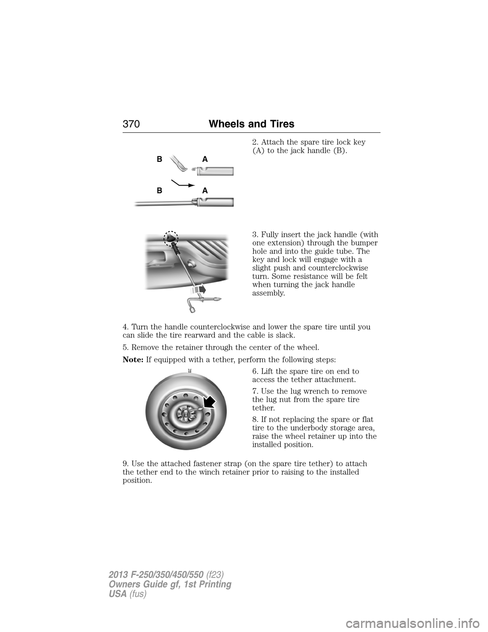
Note:If equipped with a tether, perform the following steps:
6. Lift the spare tire on end to
access the tether attachment.
7. Use the lug wrench to remove
the lug nut from the spare tire
tether.
8. If not replacing the spare or flat
tire to the underbody storage area,
raise the wheel retainer up into the
installed position.
9. Use the attached fastener strap (on the spare tire tether) to attach
the tether end to the winch retainer prior to raising to the installed
position.
AB
AB
370Wheels and Tires
2013 F-250/350/450/550(f23)
Owners Guide gf, 1st Printing
USA(fus)
Page 372 of 563

Tire Change Procedure
WARNING:When one of the front wheels is off the ground, the
transmission alone will not prevent the vehicle from moving or
slipping off the jack, even if the transmission selector lever is in
positionP.
WARNING:To help prevent the vehicle from moving when you
change a tire, be sure to place the transmission selector lever in
positionP, set the parking brake and block (in both directions) the
wheel that is diagonally opposite (other side and end of the vehicle) to
the tire being changed.
WARNING:Never get underneath a vehicle that is supported
only by a jack. If the vehicle slips off the jack, you or someone
else could be seriously injured.
WARNING:Do not attempt to change a tire on the side of the
vehicle close to moving traffic. Pull far enough off the road to
avoid the danger of being hit when operating the jack or changing the
wheel.
WARNING:Always use the jack provided as original equipment
with your vehicle. If using a jack other than the one provided as
original equipment with your vehicle, make sure the jack capacity is
adequate for the vehicle weight, including any vehicle cargo or
modifications.
Note:Passengers should not remain in the vehicle when the vehicle is
being jacked.
Wheels and Tires371
2013 F-250/350/450/550(f23)
Owners Guide gf, 1st Printing
USA(fus)