Page 268 of 563

WARNING(Continued)
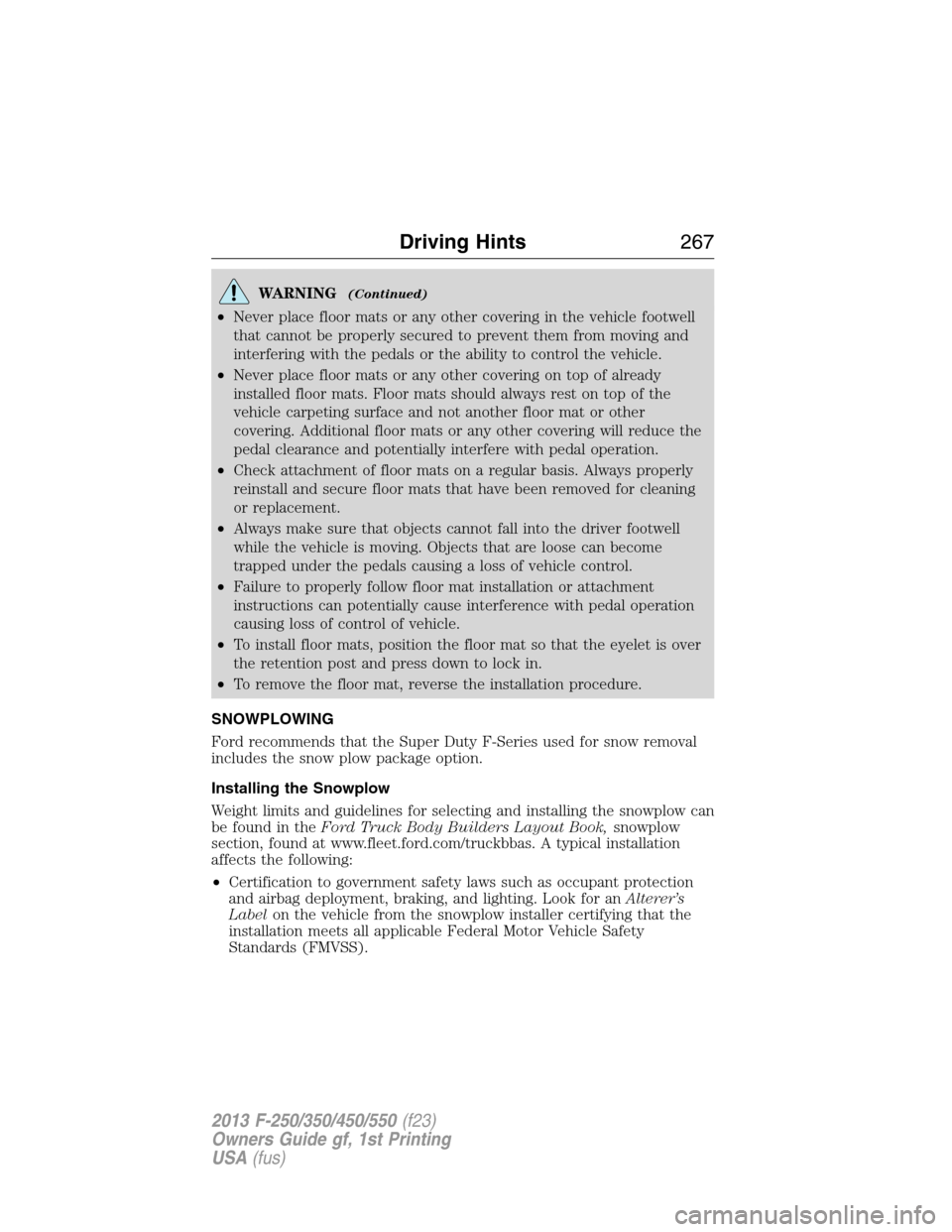
•Never place floor mats or any other covering in the vehicle footwell
that cannot be properly secured to prevent them from moving and
interfering with the pedals or the ability to control the vehicle.
•Never place floor mats or any other covering on top of already
installed floor mats. Floor mats should always rest on top of the
vehicle carpeting surface and not another floor mat or other
covering. Additional floor mats or any other covering will reduce the
pedal clearance and potentially interfere with pedal operation.
•Check attachment of floor mats on a regular basis. Always properly
reinstall and secure floor mats that have been removed for cleaning
or replacement.
•Always make sure that objects cannot fall into the driver footwell
while the vehicle is moving. Objects that are loose can become
trapped under the pedals causing a loss of vehicle control.
•Failure to properly follow floor mat installation or attachment
instructions can potentially cause interference with pedal operation
causing loss of control of vehicle.
•To install floor mats, position the floor mat so that the eyelet is over
the retention post and press down to lock in.
•To remove the floor mat, reverse the installation procedure.
SNOWPLOWING
Ford recommends that the Super Duty F-Series used for snow removal
includes the snow plow package option.
Installing the Snowplow
Weight limits and guidelines for selecting and installing the snowplow can
be found in theFord Truck Body Builders Layout Book,snowplow
section, found at www.fleet.ford.com/truckbbas. A typical installation
affects the following:
•Certification to government safety laws such as occupant protection
and airbag deployment, braking, and lighting. Look for anAlterer’s
Labelon the vehicle from the snowplow installer certifying that the
installation meets all applicable Federal Motor Vehicle Safety
Standards (FMVSS).
Driving Hints267
2013 F-250/350/450/550(f23)
Owners Guide gf, 1st Printing
USA(fus)
Page 271 of 563

Transmission operation while plowing
WARNING:Do not spin the wheels at over 35 mph (55 km/h).
The tires may fail and injure a passenger or bystander.
•Shift transfer case to4L(4WD Low) when plowing in small areas at
speeds below 5 mph (8 km/h).
•Shift transfer case to4H(4WD High) when plowing larger areas or
light snow at higher speeds. Do not exceed 15 mph (24 km/h).
•Do not shift the transmission from a forward gear toR(Reverse) until
the engine is at idle and the wheels are stopped.
•If the vehicle is stuck, shift the transmission in a steady motion
between forward and reverse gears. Do not rock the vehicle for more
than a minute. The transmission and tires may be damaged or the
engine can overheat.
Outside Air Temperature While Plowing
The outside air temperature reading can be inaccurate while plowing
with your vehicle due to the sensor air flow being blocked by the plow
blade.
A Ford Wiring Kit (XXXX-XXXXX-XX) is available to relocated the OAT
sensor to the plow blade frame below the headlamp to provide accurate
outside air temperature readings.
VEHICLE USED AS A STATIONARY POWER SOURCE
Auxiliary equipment called power take-off, or PTO, is often added to the
engine or transmission to operate utility equipment. Examples include a
wheel-lift for tow trucks, cranes, tools for construction or tire service,
and pumping fluids. PTO applications draw auxiliary horsepower from
the powertrain, often while the vehicle is stationary. In this condition,
there is limited cooling air flow through the radiator and around the
vehicle that normally occurs when a vehicle is moving. The aftermarket
PTO system installer, having the most knowledge of the final application,
is responsible for determining whether additional chassis heat protection
or powertrain cooling is required, and alerting the user to the safe and
proper operation.
Ford Super Duty Vehicles are approved for use as a stationary (including
split shaft capability) or mobile power source, within limits and operating
guidelines detailed in theFord Truck Body Builders Layout Book,
found at www.fleet.ford.com/truckbbas, and through the Ford Truck
Body Builders Advisory Service.
270Driving Hints
2013 F-250/350/450/550(f23)
Owners Guide gf, 1st Printing
USA(fus)
Page 272 of 563

ROADSIDE ASSISTANCE
Vehicles Sold in the U.S. : Getting Roadside Assistance
To fully assist you should you have a vehicle concern, Ford Motor
Company offers a complimentary roadside assistance program. This
program is separate from the New Vehicle Limited Warranty. The service
is available:
•24-hours a day, seven days a week
•for the coverage period listed on the Roadside Assistance Card
included in your owner’s manual portfolio.
Roadside assistance will cover:
•a flat tire change with a good spare (except vehicles that have been
supplied with a tire inflation kit).
•battery jump start.
•lock-out assistance (key replacement cost is the customer’s
responsibility).
•fuel delivery – Independent Service Contractors, if not prohibited by
state, local or municipal law shall deliver up to 2.0 gallons (7.5 liters)
of gasoline or 5.0 gallons (18.9 liters) of diesel fuel to a disabled
vehicle. Fuel delivery service is limited to two no-charge occurrences
within a 12-month period.
•winch out – available within 100 feet (30.5 meters) of a paved or
county maintained road, no recoveries.
•towing – Ford and Lincoln eligible vehicles towed to an authorized
dealer within 35 miles (56 kilometers) of the disablement location or
to the nearest authorized dealer. If a member requests to be towed to
an authorized dealer more than 35 miles (56 kilometers) from the
disablement location, the member shall be responsible for any mileage
costs in excess of 35 miles (56 kilometers).
Trailers shall be covered up to $200 if the disabled eligible vehicle
requires service at the nearest authorized dealer. If the trailer is disabled,
but the towing vehicle is operational, the trailer does not qualify for any
roadside services.
Roadside Emergencies271
2013 F-250/350/450/550(f23)
Owners Guide gf, 1st Printing
USA(fus)
Page 289 of 563

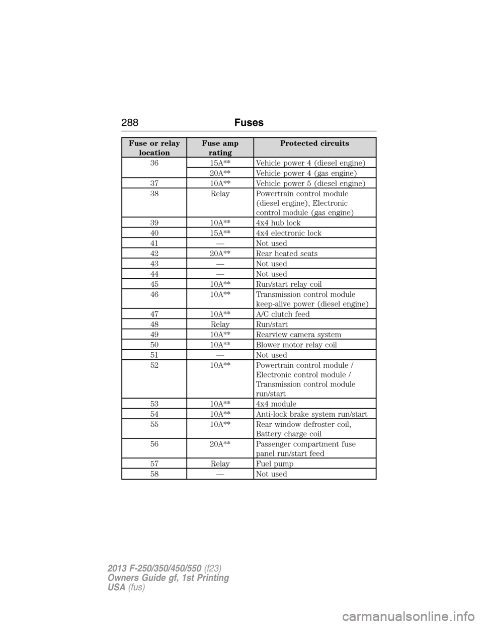
Fuse or relay
locationFuse amp
ratingProtected circuits
36 15A** Vehicle power 4 (diesel engine)
20A** Vehicle power 4 (gas engine)
37 10A** Vehicle power 5 (diesel engine)
38 Relay Powertrain control module
(diesel engine), Electronic
control module (gas engine)
39 10A** 4x4 hub lock
40 15A** 4x4 electronic lock
41 — Not used
42 20A** Rear heated seats
43 — Not used
44 — Not used
45 10A** Run/start relay coil
46 10A** Transmission control module
keep-alive power (diesel engine)
47 10A** A/C clutch feed
48 Relay Run/start
49 10A** Rearview camera system
50 10A** Blower motor relay coil
51 — Not used
52 10A** Powertrain control module /
Electronic control module /
Transmission control module
run/start
53 10A** 4x4 module
54 10A** Anti-lock brake system run/start
55 10A** Rear window defroster coil,
Battery charge coil
56 20A** Passenger compartment fuse
panel run/start feed
57 Relay Fuel pump
58 — Not used
288Fuses
2013 F-250/350/450/550(f23)
Owners Guide gf, 1st Printing
USA(fus)
Page 290 of 563
Fuse or relay
locationFuse amp
ratingProtected circuits
59 — Not used
60 — Not used
61 — Not used
62 — Not used
63 — Not used
64 — Not used
65 — Not used
66 20A** Fuel pump
67 — Not used
68 10A** Fuel pump relay coil
69 — Not used
70 10A** Trailer tow backup lamp
71 10A** Canister vent (gas engine)
72 10A** Powertrain control module /
Electronic control module relay
coil feed keep-alive power
73 — Not used
74 Relay Trailer tow left-hand stop/turn
75 Relay Trailer tow right-hand stop/turn
76 Relay Backup lamp
77 — Not used
78 — Not used
79 — Not used
80 — Not used
81 — Not used
82 20A* Auxiliary power point #2
83 20A* Auxiliary power point #1
84 30A* 4x4 shift motor
85 30A* Heated/cooled seats
86 25A* Anti-lock brake system coil feed
87 20A* Auxiliary power point #5
Fuses289
2013 F-250/350/450/550(f23)
Owners Guide gf, 1st Printing
USA(fus)
Page 291 of 563
Fuse or relay
locationFuse amp
ratingProtected circuits
88 20A* Auxiliary power point #6
89 40A* Starter motor
90 25A* Trailer tow battery charge
91 — Not used
92 20A* Auxiliary power point #4
93 20A* Auxiliary power point #3
94 25A* Upfitter #1
95 25A* Upfitter #2
96 50A* Anti-lock brake system pump
97 40A* Inverter
98 — Not used
99 40A* Instrument panel power inverter
100 25A* Trailer tow turn signals
101 Relay Starter
102 Relay Trailer tow battery charge
103 — Not used
104 — Not used
105 — Not used
106 — Not used
107 — Not used
* Cartridge fuses ** Mini fuses
Passenger Compartment Fuse Panel
The fuse panel is located in the
passenger’s footwell. Remove the
panel cover to access the fuses.
290Fuses
2013 F-250/350/450/550(f23)
Owners Guide gf, 1st Printing
USA(fus)
Page 293 of 563

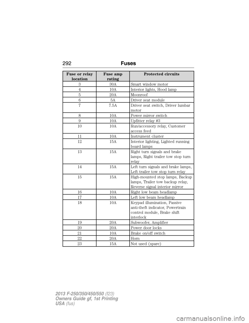
Fuse or relay
locationFuse amp
ratingProtected circuits
3 30A Smart window motor
4 10A Interior lights, Hood lamp
5 20A Moonroof
6 5A Driver seat module
7 7.5A Driver seat switch, Driver lumbar
motor
8 10A Power mirror switch
9 10A Upfitter relay #3
10 10A Run/accessory relay, Customer
access feed
11 10A Instrument cluster
12 15A Interior lighting, Lighted running
board lamps
13 15A Right turn signals and brake
lamps, Right trailer tow stop turn
relay
14 15A Left turn signals and brake lamps,
Left trailer tow stop turn relay
15 15A High-mounted stop lamps, Backup
lamps, Trailer tow backup relay,
Reverse signal interior mirror
16 10A Right low beam headlamp
17 10A Left low beam headlamp
18 10A Keypad illumination, Passive
anti-theft indicator, Powertrain
control module, Brake shift
interlock
19 20A Subwoofer, Amplifier
20 20A Power door locks
21 10A Brake on/off switch
22 20A Horn
23 15A Not used (spare)
292Fuses
2013 F-250/350/450/550(f23)
Owners Guide gf, 1st Printing
USA(fus)
Page 294 of 563

Fuse or relay
locationFuse amp
ratingProtected circuits
24 15A Steering wheel control module,
Diagnostic connector, Power fold
mirror relay, Remote keyless
entry, Electronic finish panel
25 15A Not used (spare)
26 5A Steering wheel control module
27 20A Not used (spare)
28 15A Ignition switch
29 20A SYNC, GPS module, Radio
faceplate
30 15A Parking lamp relay, Trailer tow
parking lamp relay
31 5A Trailer brake controller (brake
signal), Customer access
32 15A Moonroof motor, Telescoping
mirror switch, Auto dimming
mirrors, Power inverter, Driver
and passenger door lock switch
illumination, Rear heated seat
switch illumination
33 10A Restraint control module
34 10A Heated steering wheel module,
Rear heated seats module
35 5A Select shift switch, Reverse park
aid module, Trailer brake control
module
36 10A Fuel tank select switch
37 10A PTC heater
38 10A AM/FM radio faceplate
39 15A High beam headlamps
40 10A Parking lamps (in mirrors), Roof
marker lamps
Fuses293
2013 F-250/350/450/550(f23)
Owners Guide gf, 1st Printing
USA(fus)