2013 FORD F250 lock
[x] Cancel search: lockPage 251 of 577
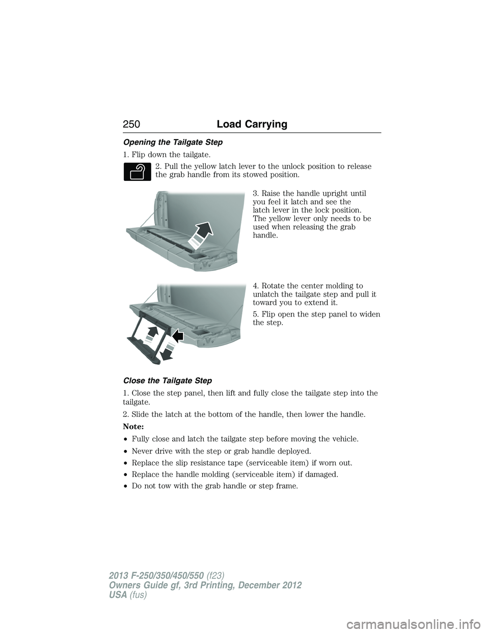
Opening the Tailgate Step
1. Flip down the tailgate.
2. Pull the yellow latch lever to the unlock position to release
the grab handle from its stowed position.
3. Raise the handle upright until
you feel it latch and see the
latch lever in the lock position.
The yellow lever only needs to be
used when releasing the grab
handle.
4. Rotate the center molding to
unlatch the tailgate step and pull it
toward you to extend it.
5. Flip open the step panel to widen
the step.
Close the Tailgate Step
1. Close the step panel, then lift and fully close the tailgate step into the
tailgate.
2. Slide the latch at the bottom of the handle, then lower the handle.
Note:
•Fully close and latch the tailgate step before moving the vehicle.
•Never drive with the step or grab handle deployed.
•Replace the slip resistance tape (serviceable item) if worn out.
•Replace the handle molding (serviceable item) if damaged.
•Do not tow with the grab handle or step frame.
250Load Carrying
2013 F-250/350/450/550(f23)
Owners Guide gf, 3rd Printing, December 2012
USA(fus)
Page 252 of 577
BED EXTENDER (IF EQUIPPED)
Note:This feature is not intended for off-road usage.
Note:Make sure the locking pins and knobs are fully engaged when the
vehicle is in motion.
Note:Make sure all cargo is secured.
Note:The tailgate load must not exceed 150 pounds (68 kilograms)
when the vehicle is in motion.
Note:The bed extender should always be kept in the grocery mode or
stowed position with the tailgate closed when not being used for the
purpose of restraining cargo in the tailgate mode.
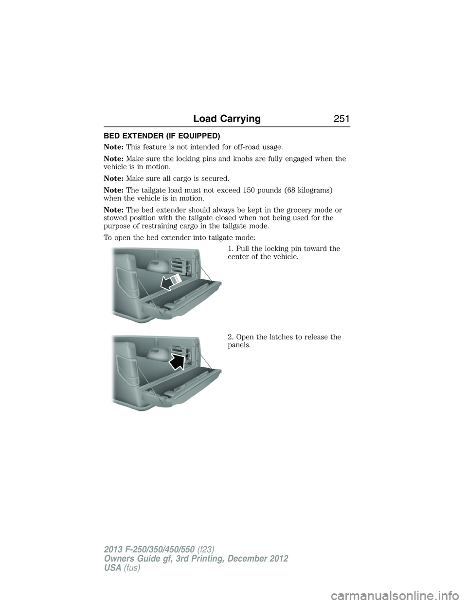
To open the bed extender into tailgate mode:
1. Pull the locking pin toward the
center of the vehicle.
2. Open the latches to release the
panels.
Load Carrying251
2013 F-250/350/450/550(f23)
Owners Guide gf, 3rd Printing, December 2012
USA(fus)
Page 253 of 577
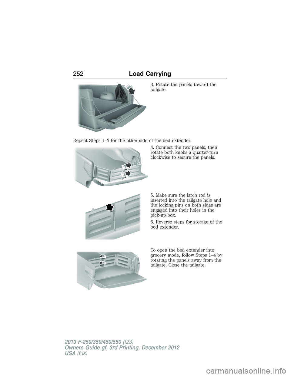
3. Rotate the panels toward the
tailgate.
Repeat Steps 1–3 for the other side of the bed extender.
4. Connect the two panels, then
rotate both knobs a quarter-turn
clockwise to secure the panels.
5. Make sure the latch rod is
inserted into the tailgate hole and
the locking pins on both sides are
engaged into their holes in the
pick-up box.
6. Reverse steps for storage of the
bed extender.
To open the bed extender into
grocery mode, follow Steps 1–4 by
rotating the panels away from the
tailgate. Close the tailgate.
252Load Carrying
2013 F-250/350/450/550(f23)
Owners Guide gf, 3rd Printing, December 2012
USA(fus)
Page 256 of 577
Note:Certain states require electric trailer brakes for trailers over a
specified weight. Be sure to check state regulations for this specified
weight. The maximum trailer weights listed may be limited to this
specified weight, as your vehicle’s electrical system may not include
the wiring connector needed to use electric trailer brakes.
Your vehicle may tow a class I, II, III and IV trailer or fifth-wheel trailer
provided the maximum trailer weight is less than or equal to the maximum
trailer weight listed for your engine and rear axle ratio on the following
chart.
To calculate the maximum loaded trailer weight for your vehicle:
1. Start with the gross combined weight rating for your vehicle model
and axle ratio. See the following chart.
2. Subtract all of the following that apply to your vehicle:
•Vehicle curb weight
•Hitch hardware weight, such as a draw bar, ball, locks or weight
distributing
•Driver weight
•Passenger(s) weight
•Payload, cargo and luggage weight
•Aftermarket equipment weight.
3. This equals the maximum loaded trailer weight for this combination.
Note:The trailer tongue load figures into the payload for your vehicle.
Reduce the total payload by the final trailer tongue weight.
Consult an authorized dealer to determine the maximum trailer weight
allowed for your vehicle if you are not sure.
Further trailer and hitch restrictions exist depending on the type of
trailer and hitch listed. This information follows the table listing the
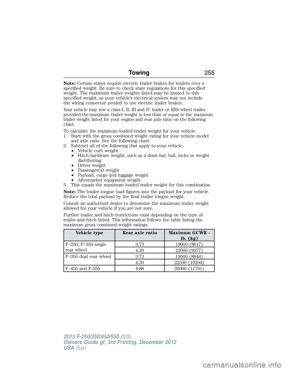
maximum gross combined weight ratings.
Vehicle type Rear axle ratio Maximum GCWR -
lb. (kg)
F–250, F–350 single
rear wheel3.73 19000 (8617)
4.30 22000 (9977)
F–350 dual rear wheel 3.73 19500 (8844)
4.30 22500 (10204)
F–450 and F-550 4.88 26000 (11791)
Towing255
2013 F-250/350/450/550(f23)
Owners Guide gf, 3rd Printing, December 2012
USA(fus)
Page 258 of 577
3. Securely attach the loaded trailer to your vehicle without the
weight-distributing bars connected.
4. Measure the height to the top of your vehicle’s front wheel opening
on the fender a second time. This is H2.
5. Install and adjust the tension in the weight-distributing bars so that
the height of your vehicle’s front wheel opening on the fender is
approximately halfway between H1 and H2.
6. Check that the trailer is level or slightly nose down toward your
vehicle. If not, adjust the ball height accordingly and repeat
Steps 2–6.
Once the trailer is level or slightly nose down toward the vehicle:
•Lock the bar tension adjuster in place.
•Check that the trailer tongue securely attaches and locks onto the
hitch.
•Install safety chains, lighting, and trailer brake controls as required by
law or the trailer manufacturer.
Fifth-Wheel Trailer Hitch (If Equipped)
WARNING:The mounting pads in the bed are specifically
designed for certain fifth-wheel trailer hitches and gooseneck ball
hitches. Do not use these mounting pads for other purposes. Doing so
could result in vehicle structural damage, loss of vehicle control, and
personal injury. Contact an authorized dealer to purchase gooseneck
and fifth-wheel hitches that are compatible with your vehicle.
WARNING:Towing trailers beyond the maximum limit of the
towing system could result in vehicle structural damage, loss of
vehicle control and personal injury.
WARNING:The hitch rating listed on the trailer hitch label is
the maximum possible trailer rating. To find the maximum trailer
weight allowed for your specific vehicle, consult an authorized dealer or
theRV & Trailer Towing Guideprovided by an authorized dealer.
Your vehicle may be equipped with a fifth-wheel prep package. This
package enables your vehicle to accept certain fifth-wheel trailer hitches
and gooseneck ball hitches. The fifth-wheel trailer hitch attaches to the
four mounting pads in the pick-up bed. An optional 7–pin trailer wiring
connector may be in the bed as well. The gooseneck ball hitch is a separate
mounting pad from the fifth-wheel hitch, located in the center of the bed.
Towing257
2013 F-250/350/450/550(f23)
Owners Guide gf, 3rd Printing, December 2012
USA(fus)
Page 262 of 577
The gain should be set to provide the maximum trailer braking assistance
while making sure the trailer wheels do not lock when using the brakes.
Locked trailer wheels may lead to trailer instability.
1. Make sure the trailer brakes are in good working condition,
functioning normally and properly adjusted. See your trailer dealer if
necessary.
2. Hook up the trailer and make the electrical connections according to
the trailer manufacturer’s instructions.
3. When you plug in a trailer with electric or electric-over-hydraulic
brakes,TRAILER CONNECTEDappears in the information display.
4. Use the gain adjustment (+ and -) buttons to increase or decrease
the gain setting to the desired starting point. A gain setting of 6.0 is a
good starting point for heavier loads.
5. In a traffic-free environment, tow the trailer on a dry, level surface at
a speed of 20–25 mph (30–40 km/h) and squeeze the manual control
lever completely.
6. If the trailer wheels lock up, indicated by squealing tires, reduce the
gain setting. If the trailer wheels turn freely, increase the gain setting.
Repeat Steps 5 and 6 until the gain setting is at a point just below
trailer wheel lock-up. If towing a heavier trailer, trailer wheel lock-up
may not be attainable even with the maximum gain setting of 10.
Explanation of Information Display Warning Messages
Note:An authorized dealer can diagnose the trailer brake controller to
determine exactly which trailer fault has occurred. However, your Ford
warranty doesnotcover this diagnosis if the fault is with the trailer.
TRAILER BRAKE MODULE FAULT:Displays in response to faults
sensed by the trailer brake controller, accompanied by a single chime.
If this message appears, contact an authorized dealer as soon as possible
for diagnosis and repair. The controller may still function, but
performance may be degraded.
WIRING FAULT ON TRAILER:Displays when there is a short circuit
on the electric brake output wire. If theWIRING FAULT ON TRAILER
message displays, accompanied by a single chime, with no trailer
connected, the problem is with your vehicle wiring between the trailer
brake controller and the 7–pin connector at the bumper. If the message
only displays with a trailer connected, the problem is with the trailer
wiring. Consult your trailer dealer for assistance. This can be a short to
ground (such as a chaffed wire), short to voltage (such as a pulled pin
on trailer emergency breakaway battery) or the trailer brakes may be
drawing too much current.
Towing261
2013 F-250/350/450/550(f23)
Owners Guide gf, 3rd Printing, December 2012
USA(fus)
Page 263 of 577
Points to Remember
Note:Do not attempt removal of the trailer brake controller without
consulting theWorkshop Manual.Damage to the unit may result.
•Adjust gain setting before using the trailer brake controller for the
first time.
•Adjust gain setting, using the procedure above, whenever road,
weather and trailer or vehicle loading conditions change from when
the gain was initially set.
•Only use the manual control lever for proper adjustment of the gain
during trailer setup. Misuse, such as application during trailer sway,
could cause instability of trailer or tow vehicle.
•Avoid towing in adverse weather conditions. The trailer brake
controller does not provide anti-lock control of the trailer wheels.
Trailer wheels can lock up on slippery surfaces, resulting in reduced
stability of trailer and tow vehicle.
•The trailer brake controller is equipped with a feature that reduces
output at vehicle speeds below 11 mph (18 km/h) so trailer and
vehicle braking is not jerky or harsh. This feature is only available
when applying the brakes using your vehicle’s brake pedal, not the
controller.
•The controller interacts with the brake control system and powertrain
control system of your vehicle to provide the best performance on
different road conditions.
•Your vehicle’s brake system and the trailer brake system work
independently of each other. Changing the gain setting on the
controller does not affect the operation of your vehicle’s brakes
whether you attach a trailer or not.
•When you turn the engine off, the controller output is disabled and
the display and module shut down. The controller module and display
turn on when you turn the ignition on.
•The trailer brake controller is only a factory-installed or
dealer-installed item. Ford is not responsible for warranty or
performance of the controller due to misuse or customer installation.
262Towing
2013 F-250/350/450/550(f23)
Owners Guide gf, 3rd Printing, December 2012
USA(fus)
Page 268 of 577
We recommend the use of a wheel lift and dollies or flatbed equipment
to tow your vehicle. Do not tow with a slingbelt. Ford Motor Company
has not approved a slingbelt towing procedure. Vehicle damage may
occur if towed incorrectly, or by any other means.
Ford Motor Company produces a towing manual for all authorized tow
truck operators. Have your tow truck operator refer to this manual for
proper hook-up and towing procedures for your vehicle.
It is acceptable to have your two-wheel drive vehicle towed with the
front wheels on the ground (without dollies) and the rear wheels off the
ground.
We recommend towing a four-wheel drive vehicle with all wheels off the
ground, such as using a wheel lift and dollies or flatbed equipment.
However, it is acceptable to use a wheel lift to raise the rear of your
vehicle so long as, depending on vehicle configuration, you perform the
following before towing:
•If your vehicle is equipped with a manual-shift transfer case, make
sure the front wheel hub locks are in theFREEposition before
towing.
•If your vehicle is equipped with an electronic shift-on-the-fly transfer
case, make sure you turn the four-wheel drive control to the2L
position before towing.
Note:Towing an electronic shift-on-the-fly four-wheel drive vehicle with
the front wheels on the ground without disengaging the front hubs may
cause damage to the automatic transmission.
Note:Towing a two-wheel drive vehicle or an electronic shift-on-the-fly
four-wheel drive vehicle with the rear wheels on the ground for more
than 50 miles (80 km) or faster than 35 mph (56 km/h) may cause
damage to the automatic transmission.
Note:Using wheel lift equipment to tow a dual rear wheel vehicle
requires removing an outer rear wheel before towing.
Towing267
2013 F-250/350/450/550(f23)
Owners Guide gf, 3rd Printing, December 2012
USA(fus)