2013 FIAT FREEMONT lock
[x] Cancel search: lockPage 117 of 352

LIFTGATE
The liftgate can be unlocked or locked with the Re-
mote Keyless Entry (RKE) transmitter, the Keyless
EnterNGo™ (Passive Entry) or by activating the
power door lock switch located on either front door
trim panel.
For further information on Keyless EnterNGo™
(Passive Entry), refer to “Keyless EnterNGo™” in
“Starting And Driving”.
NOTE:The liftgate cannot be unlocked or locked
with the manual door lock plungers on the door trim
panels or the door lock cylinder on the driver's door.
To open the unlocked liftgate, squeeze the handle and
pull the liftgate toward you. Gas props will raise and
support the liftgate in the open position. (fig. 91)
NOTE: Because the gas pressure drops with tem-
perature, it may be necessary to assist the props when
opening the liftgate in cold weather.
WARNING!
Dr
iving with the liftgate open can
allow poisonous exhaust gases into your
vehicle. These fumes could injure you and your
passengers. Keep the liftgate closed when you are
operating the vehicle.
If you are required to drive with the liftgate
open, make sure that all windows are closed, and
the blower switch on the climate control is set at
high speed. Do not use the recirculation mode.
(fig. 91) Liftgate Release
111
KNOWING
YOUR
VEHICLE
SAFETY
S
TARTING
AND
DRIVING
WARNING
LIGHTS
AND
MESSAGES
IN AN
EMERGENCY
SERVICING
AND
CARETECHNICAL
SPECIFICATIONSCONTENTS
Page 123 of 352

To prevent possible damage:
Before closing hood, make sure the
hood prop rod is fully seated into its
storage retaining clips.
Do not slam the hood to close it . Use a firm
downward push at the center front edge of the
hood to ensure that both latches engage. Never
drive your vehicle unless the hood is fully closed,
with both latches engaged.
WARNING!
Be sure the hood is fully latched before
dr
iving your vehicle. If the hood is not
fully latched, it could open when the vehicle is in
motion and block your vision. Failure to follow
this warning could result in serious injury or
death. ROOF LUGGAGE RACK (for
versions/markets, where
provided)
The roof rack side rails on your vehicle are NOT
designed to carry a load without the addition of cross-
bars. Metal Crossbars can be purchased from your
FIAT dealer to provide a functional roof rack system.
External racks do not increase the total load carrying
capacity of the vehicle. Be sure that the total occupant
and luggage load inside the vehicle plus the load on the
luggage rack do not exceed the maximum vehicle load
capacity.
The roof rack cross rails and side rails together are
designed to carry cargo weight. The load must not
exceed 68 kg, and it should be distributed uniformly
over the cross rails.
117
KNOWING
YOUR
VEHICLE
SAFETY
STARTING
AND
DRIVING
WARNING
LIGHTS
AND
MESSAGES
IN AN
EMERGENCY
SERVICING
AND
CARETECHNICAL
SPECIFICATIONSCONTENTS
Page 125 of 352

WARNING!
Ri
ding the brakes can lead to brake
failure and possibly a collision. Driving
with your foot resting or riding on the brake
pedal can result in abnormally high brake tem-
peratures, excessive lining wear, and possible
brake damage.You would not have your full brak-
ing capacity in an emergency.
Driving a vehicle with the “Brake Warning
Light” on is dangerous. A significant decrease in
braking performance or vehicle stability during
braking may occur. It will take you longer to stop
the vehicle or will make your vehicle harder to
control. You could have a collision. Have the ve-
hicle checked immediately.
ANTI-LOCK BRAKE SYSTEM (ABS)
This system aids the driver in maintaining vehicle con-
trol under adverse braking conditions. The system
controls hydraulic brake pressure to prevent wheel
lock-up to help avoid skidding on slippery surfaces
during braking. Refer to “Anti-Lock Brake System
(ABS)” under “Knowing Your Vehicle/Electronic Brake
Control System” for further information.
WARNING!
The ABS cannot prevent the natural laws
of
physics from acting on the vehicle, nor
can it increase the traction afforded by prevailing
road conditions. ABS cannot prevent accidents,
including those resulting from excessive speed in
turns, driving on very slippery surfaces, or hydro-
planing.The capabilities of an ABS-equipped ve-
hicle must never be exploited in a reckless or
dangerous manner, which could jeopardize the
user's safety or the safety of others.
119
KNOWING
YOUR
VEHICLE
SAFETY
STARTING
AND
DRIVING
WARNING
LIGHTS
AND
MESSAGES
IN AN
EMERGENCY
SERVICING
AND
CARETECHNICAL
SPECIFICATIONSCONTENTS
Page 126 of 352

ELECTRONIC BRAKE CONTROL
SYSTEM
Your vehicle is equipped with an advanced electronic
brake control system commonly referred to as ESC.
This system includes Anti-Lock Brake System (ABS),
Brake Assist System (BAS), Traction Control System
(TCS), Electronic Roll Mitigation (ERM), Electronic
Stability Control (ESC), and Trailer Sway Control
(TSC). These systems work together to enhance both
vehicle stability and control in various driving condi-
tions.
ANTI-LOCK BRAKE SYSTEM (ABS)
The Anti-Lock Brake System (ABS) provides increased
vehicle stability and brake performance under most
braking conditions. The system automatically “pumps”
the brakes during severe braking conditions to prevent
wheel lock-up.
When the vehicle is driven over 11 km/h, you may also
hear a slight clicking sound as well as some related
motor noises. These noises are the system performing
its self check cycle to ensure that the ABS is working
properly. This self check occurs each time the vehicle is
started and accelerated past 11 km/h.
ABS is activated during braking under certain road or
stopping conditions. ABS-inducing conditions can in-clude ice, snow, gravel, bumps, railroad tracks, loose
debris, or panic stops.
You also may experience the following when the brake
system goes into Anti-lock:
The ABS motor running (it may continue to run for a
short time after the stop)
The clicking sound of solenoid valves
Brake pedal pulsations
A slight drop or fall away of the brake pedal at the end of the stop
These are all normal characteristics of ABS.
WARNING!
Th
e ABS contains sophisticated elec-
tronic equipment that may be suscep-
tible to interference caused by improperly in-
stalled or high output radio transmitting
equipment . This interference can cause possible
loss of anti-lock braking capability. Installation
of such equipment should be performed by quali-
fied professionals.
(Continued)
120
KNOWING YOUR
VEHICLE
SAFETY
S
TARTING AND
DRIVING
WARNING LIGHTSAND
MESSAGES
IN AN
EMERGENCY
SERVICING AND
CARETECHNICAL
SPECIFICATIONSCONTENTS
Page 127 of 352

(Continued)
Pumping of the Anti-Lock Brakes will diminish
their effectiveness and may lead to an accident .
Pumping makes the stopping distance longer. Just
press firmly on your brake pedal when you need
to slow down or stop.
The ABS cannot prevent the natural laws of
physics from acting on the vehicle, nor can it
increase braking or steering efficiency beyond
that afforded by the condition of the vehicle
brakes and tires or the traction afforded.
The ABS cannot prevent accidents, including
those resulting from excessive speed in turns,
following another vehicle too closely, or hydro-
planing.
The capabilities of an ABS equipped vehicle
must never be exploited in a reckless or danger-
ous manner, which could jeopardize the user's
safety or the safety of others.
All vehicle wheels and tires must be the same size and
type and tires must be properly inflated to produce
accurate signals for the computer. Anti-Lock Brake Light
The Anti-Lock Brake Light monitors the ABS.
The light will turn on when the ignition
switch is turned to the ON position and may
stay on for as long as four seconds.
If the ABS Light remains on or comes on while driving,
it indicates that the Anti-Lock portion of the brake
system is not functioning and that service is required.
However, the conventional brake system will continue
to operate normally if the Brake System Warning Light
is not on.
If the ABS Light is on, the brake system should be
serviced as soon as possible to restore the benefits of
Anti-Lock brakes. If the ABS Light does not come on
when the ignition switch is turned to the ON position,
have the light repaired as soon as possible.
If both the Brake System Warning Light and the ABS
Light remain on, the ABS and Electronic Brake Force
Distribution (EBD) systems are not functioning. Imme-
diate repair to the ABS system is required.
121KNOWING
YOUR
VEHICLE
SAFETY
S
TARTING
AND
DRIVING
WARNING
LIGHTS
AND
MESSAGES
IN AN
EMERGENCY
SERVICING
AND
CARETECHNICAL
SPECIFICATIONSCONTENTS
Page 158 of 352

16. BACK – When navigating in menu mode, press toreturn to the previous screen. When navigating a
DVDs disc menu, the operation depends on the
disc’s contents.
17. ◂◂– In radio modes, press to seek to the previous
tunable station. In disc modes, press and hold to
fast rewind through the current audio track or
video chapter. In menu modes use to navigate in
the menu.
18. ENTER – Press to select the highlighted option in a menu.
19. ▴/ NEXT – In radio modes, press to select to the
next station. In disc modes, press to advance to
the next audio track or video chapter. In menu
modes, use to navigate in the menu.
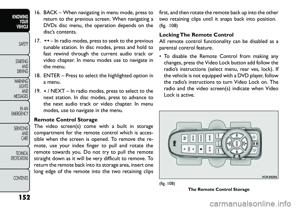
Remote Control Storage
The video screen(s) come with a built in storage
compartment for the remote control which is acces-
sible when the screen is opened. To remove the re-
mote, use your index finger to pull and rotate the
remote towards you. Do not try to pull the remote
straight down as it will be very difficult to remove. To
return the remote back into its storage area, insert one
long edge of the remote into the two retaining clips first, and then rotate the remote back up into the other
two retaining clips until it snaps back into position.
(fig. 108)
Locking The Remote Control
All remote control functionality can be disabled as a
parental control feature.
To disable the Remote Control from making any
changes, press the Video Lock button add follow the
radio’s instructions (select menu, rear ves, lock). If
the vehicle is not equipped with a DVD player, follow
the radio’s instructions to turn Video Lock on. The
radio and the video screen(s) indicate when Video
Lock is active.
(fig. 108) The Remote Control Storage
152
KNOWING YOUR
VEHICLE
SAFETY
S
TARTING AND
DRIVING
WARNING LIGHTSAND
MESSAGES
IN AN
EMERGENCY
SERVICING AND
CARETECHNICAL
SPECIFICATIONSCONTENTS
Page 159 of 352

Pressing the Video Lock again or turning the ignitionOFF turns Video Lock OFF and allows remote con-
trol operation of the VES™.
Replacing The Remote Control Batteries
The remote control requires two AAA batteries for
operation. To replace the batteries:
Locate the battery compartment on the back of the remote, then slide the battery cover downward.
Replace the batteries, making sure to orient them according to the polarity diagram shown.
Replace the battery compartment cover.
Headphones Operation
The headphones receive two separate channels of
audio using an infrared transmitter from the video
screen.
If no audio is heard after increasing the volume control,
verify that the screen is turned on and in the down
position and that the channel is not muted and the
headphone channel selector switch is on the desired
channel. If audio is still not heard, check that fully
charged batteries are installed in the headphones.
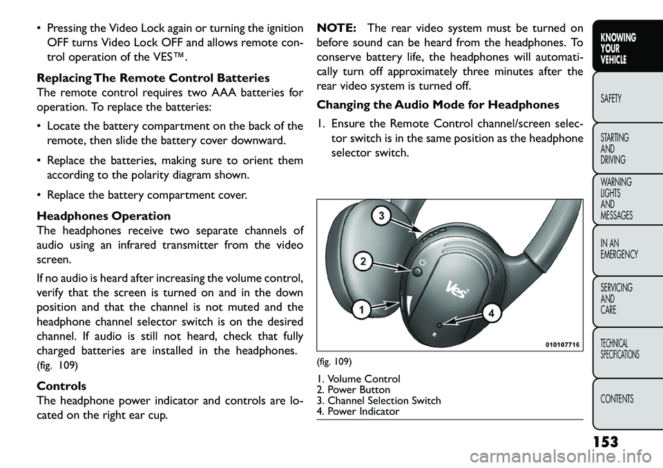
(fig. 109)
Controls
The headphone power indicator and controls are lo-
cated on the right ear cup. NOTE:
The rear video system must be turned on
before sound can be heard from the headphones. To
conserve battery life, the headphones will automati-
cally turn off approximately three minutes after the
rear video system is turned off.
Changing the Audio Mode for Headphones
1. Ensure the Remote Control channel/screen selec- tor switch is in the same position as the headphone
selector switch.
(fig. 109)1. Volume Control
2. Power Button
3. Channel Selection Switch
4. Power Indicator
153
KNOWING
YOUR
VEHICLE
SAFETY
S
TARTING
AND
DRIVING
WARNING
LIGHTS
AND
MESSAGES
IN AN
EMERGENCY
SERVICING
AND
CARETECHNICAL
SPECIFICATIONSCONTENTS
Page 164 of 352

audio for Channel 1 has been muted using the
remote control’s MUTE button.
3. Channel 2 Audio Only/Mute — Audio: Only in a single screen system: The audio only icon is dis-
played on Channel 2 when Channel 1 is in a video
mode. Mute: when the Mute icon is displayed, the
audio for Channel 2 has been muted using the
remote control’s MUTE button.
4. Channel 2 Mode — Displays the current source for Channel 2.
5. Channel 2 ENTER Button Action — When the ENTER button on the remote control is pressed
with the "INPUT FILE #" button visible on the
screen, the screen shows a numeric entry keypad
which allows you to enter a specific track number
on data discs and HDD (see Numeric Keypad Menu
section of this manual). Also, Enter Button Action –
“INPUT TRK #” to enter a specific track number on
audio discs.
6. Remote Locked Out — When the icon is displayed, the remote control functions are disabled.
7. Clock — Displays the time.
8. Channel 1 Shared Status — When the icon is displayed, the audio for Channel 1 is also shared
with the radio and playing through the cabin speak-
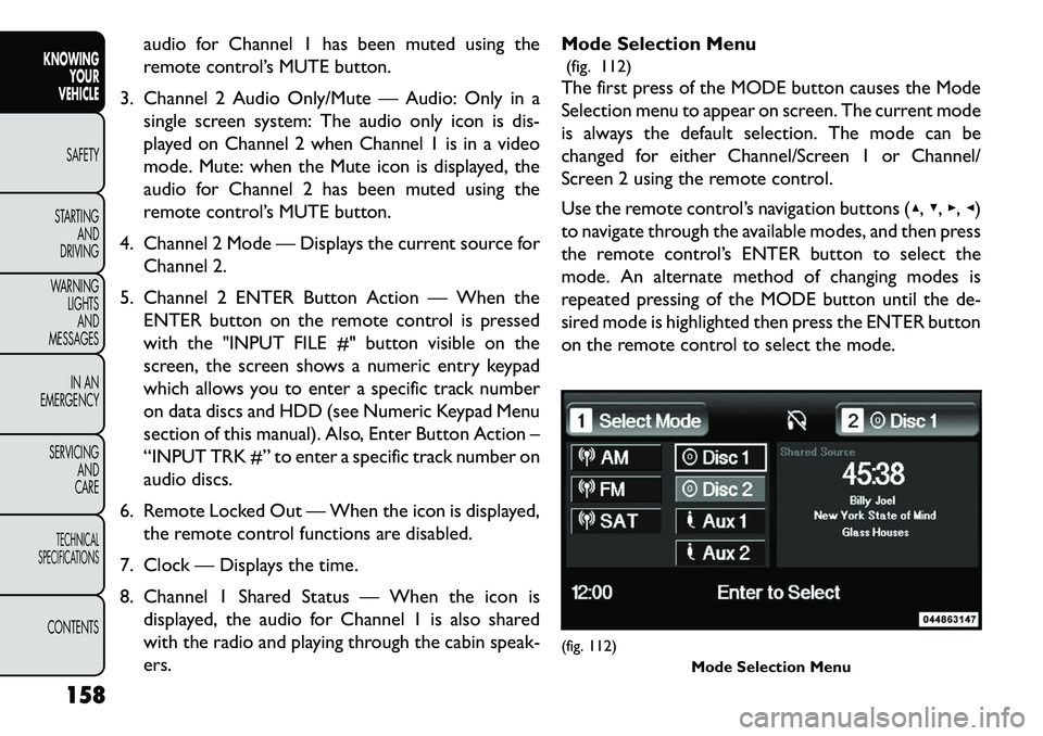
ers. Mode Selection Menu
(fig. 112)
The first press of the MODE button causes the Mode
Selection menu to appear on screen. The current mode
is always the default selection. The mode can be
changed for either Channel/Screen 1 or Channel/
Screen 2 using the remote control.
Use the remote control’s navigation buttons (▴, ▾,▸,◂)
to navigate through the available modes, and then press
the remote control’s ENTER button to select the
mode. An alternate method of changing modes is
repeated pressing of the MODE button until the de-
sired mode is highlighted then press the ENTER button
on the remote control to select the mode.
(fig. 112) Mode Selection Menu
158
KNOWING YOUR
VEHICLE
SAFETY
S
TARTING AND
DRIVING
WARNING LIGHTSAND
MESSAGES
IN AN
EMERGENCY
SERVICING AND
CARETECHNICAL
SPECIFICATIONSCONTENTS